1997 MERCEDES-BENZ ML320 reset
[x] Cancel search: resetPage 2849 of 4133
The figure may differ from this, however, depending on quality factors.
The start distance is automatically reset to its initial value by the oil change reset each time the oil is changed.
The start distance is an internal computed quantity and cannot be displayed in the instrument cluster. It is
possible to display the start distance with the HHT.
What is normally displayed in the instrument cluster is the remaining distance .
The remaining distance is the same as the start distance immediately after the oil change. On engines with oil
sensor (e.g. 112, 113, 166, 611, 668) this applies only, however, if the specified quantity of oil has been added
during the oil change.
The remaining distance is the distance which remains from the current kilometer reading until the next
service. The possible length of the interval is at least as great as the remaining distance displayed
immediately after an oil change, and is at the most twice the start distance.
The remaining distance is dependent on
the start distance
the driving conditions (a weighting of the distance driven takes place)
any oil replenishments in the case of engines with oil sensor (e.g. 112, 113, 166, 611, 668)
Consequently, ASSYST also takes into account the driving conditions: In the case of a favorable weighting
(e.g. small number of cold starts, no high engine revs, small number of short-distance trips, minimum extent of
towing a trailer etc.) and oil replenishments, the driver is provided with a bonus which extends the remaining
distance and thus the service interval. Account is also taken of whether the vehicle is actually driven or whether
the engine runs at idle speed. ASSYST is constantly supplied with the data regarding the current operating
conditions of the vehicle for this purpose.
In the case of the best weighting , only 0.6 km are added for each kilometer driven.
In the case of the most unfavorable weighting of the distance (e.g. frequent short-distance trips, large number
of cold starts), the remaining distance and thus the service interval is smaller than in the case of the most
favorable weighting (assuming identical quality factors).
In the case of the most unfavorable weighting, up to 3 km are added for each kilometer driven.
The start distance and the remaining distance are once again presented in the form of a graph in the diagram
opposite, taking the example of gasoline engines
Each time the oil is changed, the start and remaining distances are set to the initial value. In this case, the
normal value of 15 000 km is entered as the start distance (top bar) (shaded + dark section). The start distance
may differ from 15 000 km (e.g. 14 000 km; shaded section) if the quality factors do not correspond to the basic
setting. In the case of engines fitted with oil sensor (e.g. 112, 113, 166) the start distance may also be less than
15 000 km if the specified oil quantity was not added during the oil change. The remaining distance (bottom
bar) is always 15 000 km, however, immediately after an oil change. In addition, the service interval is
always at least 15 000 km .
2004 Mercedes-Benz ML350
1998-2005 GENINFO Overall vehicle - 163 Chassis
me
Saturday, October 02, 2010 3:47:47 PMPage 204 © 2006 Mitchell Repair Information Company, LLC.
Page 2852 of 4133
MODEL 129 as of 1.6.97
MODEL 140 as of 1.6.97
MODEL 163
MODEL 168
MODEL 170 as of 1.6.97
MODEL 202 as of 1.6.97
MODEL 208 up to 31.7.99
MODEL 210 as of 1.3.97 up to 30.6.99
Start time and remaining time
Start time refers to the service interval in days immediately after the oil change
The start time is not dependent on the driving conditions and any oil replenishments .
The start time is 730 days ( 365 days).
The start time is automatically reset to its initial value by the oil change reset after each oil change. The start
time is an internal computed variable and cannotbe displayed in the instrument cluster. It is possible to display
the start time with the HHT.
The remaining time is displayed in the instrument cluster under certain conditions as stated below.
The remaining time is the time which remains until the next service.
The remaining time is only of importance for "low-mileage drivers". (It is therefore the remaining distance
which is displayed as a general rule.)
The remaining time depends on:
the start time
the driving conditions (the distance driven is weighted in this case.)
Replenishing oil, however, does not have any influence on the remaining time.
As a result of these dependent factors, ASSYST proves to be a demand-oriented system even for "low-mileage
drivers". Depending on the weighting of the factors, the service interval for "low-mileage drivers" is between 1
and 2
years.
2004 Mercedes-Benz ML350
1998-2005 GENINFO Overall vehicle - 163 Chassis
me
Saturday, October 02, 2010 3:47:47 PMPage 207 © 2006 Mitchell Repair Information Company, LLC.
Page 2855 of 4133
An excess oil level or insufficient oil level appears in the display together with the oil can symbol.
Display of low oil level at maximum:
at driver request
Display of warnings:
automatically, at the earliest 60s after engine start and oil temperature greater than 60°C:
if oil level too high: the oil can symbol appears together with the readout "OIL LEVEL ABOVE
MAX". In addition, a brief warning signal sounds. (On models not fitted with multifunction
display, "HI" appears flashing.)
if oil level too low: the oil can symbol appears together with the readout "OIL LEVEL BELOW
MIN". In addition, a brief warning signal sounds. (On models not fitted with multifunction display,
the oil level warning lamp (A1e12) comes on and the readout "-2L" appears flashing.)
if oil at minimum: the oil can symbol appears together with the readout "OIL LEVEL MINIMUM".
In addition, a brief warning signal sounds. (On models not fitted with multifunction display, the oil
level warning lamp (A1e12) comes on.)
automatically 13 s after ignition ON:
if no oil is in engine: the oil can symbol appears together with the readout "OIL LEVEL BELOW
MIN". In addition, a warning signal sounds. (On models not fitted with multifunction display, the
oil level warning lamp (A1e12) comes on and the readout "-2L" appears flashing. In addition a
brief warning signal sounds.)
The missing oil quantity displayed no longer changes during the display. In other words, any change in oil level
cannot be observed directly at the display. The new oil level is only displayed once the conditions described
below exist.
Display of oil quantity at driver request
The text "DISPLAY OIL LEVEL?" appears 10 s after the start switch has been turned into position "2" (on
models not fitted with multifunction display, the oil can and the clock symbol are displayed).
If the reset button of the trip counter is pressed twice within one sec. during this readout, for example, "add 1.0L
oil" (or "-1.0L")
appears in the display if oil level too low. The readout appears only after the elapse of a waiting time after
engine OFF. The waiting time depends on the engine oil temperature.
It is
up to 20°C 30 minutes
from 60°C 1 minute
The waiting time is between these two limits at other engine oil temperatures.
2004 Mercedes-Benz ML350
1998-2005 GENINFO Overall vehicle - 163 Chassis
me
Saturday, October 02, 2010 3:47:47 PMPage 210 © 2006 Mitchell Repair Information Company, LLC.
Page 2856 of 4133
Possible readouts are (text in parenthesis relates to models not fitted with multifunction display.):
"OIL LEVEL OKAY" ("o.k."),
1.0L, 1.5L, 2L,
"Overfilling" ("HI"),
"OBSERVE WAITING TIME" (clock symbol flashing and oil can symbol),
"DISPLAY OIL LEVEL" (clock and oil can symbols.)
If there is a fault at the oil sensor (oil level/temperature/quality, B40) the oil can symbol and the text "OIL
LEVEL SENSOR FAULTY" appears only 30 s after the fault has occurred.
(On models not fitted with multifunction display, the oil level warning lamp (A1e12) comes on accordingly.)
For diagnosis, read also the injection system control module (N3) with the HHT. (The instrument cluster (A1)
receives the sensor data through the CAN from the injection system control module (N3)).
Oil change
The ASSYST has to be reset each time the oil is changed. Resetting ASSYST also resets the remaining time and
the remaining distance. Resetting can be performed at the instrument cluster or using the HHT. The following
data are stored when the system is reset:
current kilometer reading rounded off to 100,
total oil replenishments in the last interval,
remaining distance,
remaining time,
product of the quality factors,
the data of the last 5 resettings in 5 data sets
These data can only be read with the HHT!
If the specified quantity of oil is not replenished when the oil is changed, the (internal) start distance is
reduced.
Detecting oil replenishments
With the HHT it is possible to retrieve the last 10 oil replenishments and the corresponding kilometer
readings of the current interval.
In the normal case, detection of an oil replenishment is displayed by the remaining distance in the
instrument cluster being extended
Oil replenishments are always only detected once the following conditions are met:
the replenished quantit
y is at least
2004 Mercedes-Benz ML350
1998-2005 GENINFO Overall vehicle - 163 Chassis
me
Saturday, October 02, 2010 3:47:47 PMPage 211 © 2006 Mitchell Repair Information Company, LLC.
Page 2860 of 4133
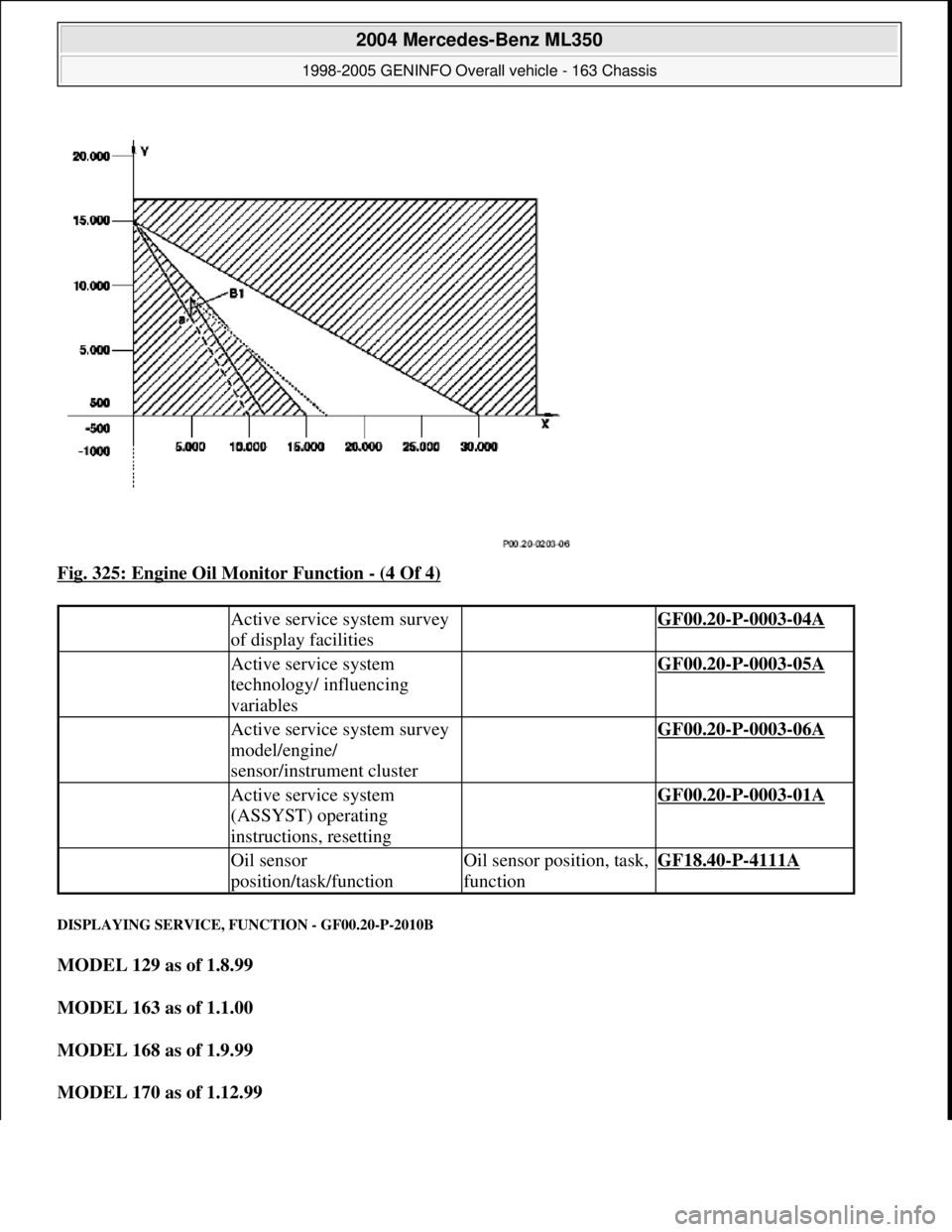
Fig. 325: Engine Oil Monitor Function - (4 Of 4)
DISPLAYING SERVICE, FUNCTION - GF00.20-P-2010B
MODEL 129 as of 1.8.99
MODEL 163 as of 1.1.00
MODEL 168 as of 1.9.99
MODEL 170 as of 1.12.99
Active service system survey
of display facilities GF00.20-P-0003-04A
Active service system
technology/ influencing
variables GF00.20-P-0003-05A
Active service system survey
model/engine/
sensor/instrument cluster GF00.20-P-0003-06A
Active service system
(ASSYST) operating
instructions, resetting GF00.20-P-0003-01A
Oil sensor
position/task/functionOil sensor position, task,
functionGF18.40-P-4111A
2004 Mercedes-Benz ML350
1998-2005 GENINFO Overall vehicle - 163 Chassis
me
Saturday, October 02, 2010 3:47:47 PMPage 215 © 2006 Mitchell Repair Information Company, LLC.
Page 3185 of 4133

AD54.30-P-2000-02GC
Notes on HHT previous knowledge diagnosis
IC
HHT :
The instrument cluster and active service system (ASSYST) sub-
function are checked with HHT, there being the choice of the
following functions for this:
1. Control module version
2. Fault memory
3. Actual values
4. Actuations
5. Control module adaptation
Additional information on test items 2, 3 and 5 can be called up using
the INPUT key
Control module adaptation
The following alternatives are available in the HHT under control
module adaptation:
1.)
Read out coding and transfer to new instrument cluster. IC and
ASSYST.
2.)
Read out/change codings e.g.:
Engine and national variants,
version of fuel tank,
special equipment etc.
3.)
Settings:
1
Clock
2
Put forward kilometer reading
3
Put back kilometer reading
4
Oil change
5
Reset oil change initiated inadvertently
6
Active Service System
7
Enter times with battery disconnected
8
Set minimum oil warning
Before replacing a defective instrument cluster, readout the existing
variant codings (driving data and instrument cluster data) and store in
the HHT on an interim basis. Read in the values stored on an interim
basis again after installing the new instrument cluster.
If it is not possible to read out the stored variant coding, all variant
codings must be input manually (menu-assistance in HHT).
When installing an instrument cluster on an experimental basis, do
not put forward the kilometer reading as it cannot be put back later.
Copyright DaimlerChrysler AG 05.06.2006 CD-Ausgabe G/10/04 . This WIS print-out will not be recorde
d by Modification services.
Page 1
Page 3285 of 4133
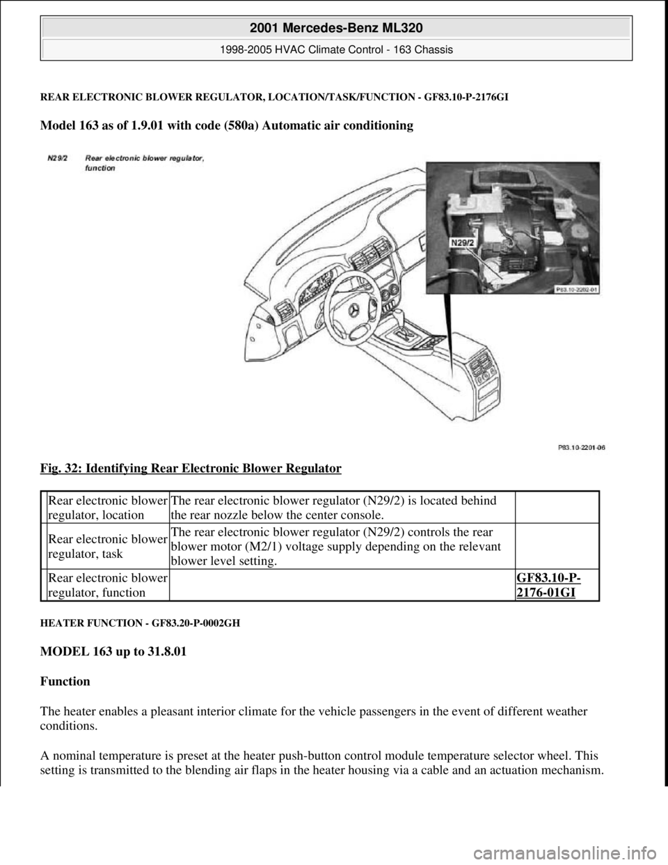
REAR ELECTRONIC BLOWER REGULATOR, LOCATION/TASK/FUNCTION - GF83.10-P-2176GI
Model 163 as of 1.9.01 with code (580a) Automatic air conditioning
Fig. 32: Identifying Rear Electronic Blower Regulator
HEATER FUNCTION - GF83.20-P-0002GH
MODEL 163 up to 31.8.01
Function
The heater enables a pleasant interior climate for the vehicle passengers in the event of different weather
conditions.
A nominal temperature is preset at the heater push-button control module temperature selector wheel. This
setting is transmitted to the blending air flaps in the heater housing via a cable and an actuation mechanism.
Rear electronic blower
regulator, locationThe rear electronic blower regulator (N29/2) is located behind
the rear nozzle below the center console.
Rear electronic blower
regulator, taskThe rear electronic blower regulator (N29/2) controls the rear
blower motor (M2/1) voltage supply depending on the relevant
blower level setting.
Rear electronic blower
regulator, function GF83.10-P-
2176-01GI
2001 Mercedes-Benz ML320
1998-2005 HVAC Climate Control - 163 Chassis
me
Saturday, October 02, 2010 3:23:15 PMPage 41 © 2006 Mitchell Repair Information Company, LLC.
Page 3325 of 4133
The residual engine heat utilization system allows the vehicle to be heated even when the ignition is
switched OFF. To do so the system utilizes the residual heat from the engine and guides it via the
blower into the passenger compartment. The heating water circulation pump ensures that the
coolant is properly circulated.
Automatic air conditioning push-button control module
The automatic air conditioning can be operated by the driver using various tip switches. Apart from this
the push-
button control module reads in different sensor signals, processes them and controls components
in the automatic air conditioning.
Rear ventilation control panel
The operator can intervene in the automatic regulation of the rear ventilation through the automatic air
conditioning by using the rear ventilation control panel and adjust it accordingly to suit needs at any
given time. With the aid of the air distribution switch and blower switch the operator can accommodate
his/her own wishes. The correspondingly altered function is then no longer regulated by the automatic air
conditioning.
By pressing the automatic control button the manually initiated settings can be reset and thus regulated
again by the automatic air conditioning.
Regulation of the air quantity and air distribution ensues thus solely by way of the automatic air
conditioning push-button control module.
Heater circuit
Coolant is heated by the engine. Subsequently, the heated coolant is then routed through the heat exchanger,
where the heat is dissipated to the air in the passenger compartment. The heater return line, in which the heating
water circulation pump is located, takes the coolant back to the coolant pump.
The heating water circulation pump ensures that the coolant is properly circulated.
The coolant flows through the heat exchanger permanently.
Depending upon the desired in-car temperature, regulation is conducted over the blending air flaps, which are
operated by the blending air flap actuator motor.
Heater operation with heater booster in vehicles with OM 612.963
In vehicles equipped with direct-injection diesel engines, an electrical heater booster is additionally installed in
the evaporator housing downstream of the heat exchanger, in order to compensate the heater output deficit
which occurs in the case of certain operating conditions.
The 3 heating elements in the heater booster are supplied with current, as a result of which they are heated and
start to glow. As a result of the structural conditions, it is ensured that the drawn in fresh air flows directly past
the electric heater booster, and is therefore heated.
2001 Mercedes-Benz ML320
1998-2005 HVAC Climate Control - 163 Chassis
me
Saturday, October 02, 2010 3:23:16 PMPage 81 © 2006 Mitchell Repair Information Company, LLC.