1997 MERCEDES-BENZ ML320 reset
[x] Cancel search: resetPage 247 of 4133
197 Driving systems
Te ch n ica l
data Instruments
and controlsOperationDrivingInstrument
cluster displayPractical hints Car care Index 3Canceling
To cancel the cruise control, briefly push lever to
position 3.
When you step on the brake pedal or the vehicle
speed drops below approximately 25 mph
(40 km / h), for example when driving upgrade, the
cruise control will be canceled.
If the cruise control cancels by itself and remains
inoperative until the engine is restarted, have the
system checked at your authorized Mercedes-Benz
Light Truck Center as soon as possible.
4Resume
If the lever is briefly pushed to position 4 when
driving at a speed exceeding approximately 25 mph
(40 km / h), the vehicle resumes the speed which
was set prior to the cancellation of the cruise
control. The last memorized speed is canceled when
the key in the steering lock is turned to position 1
or 0.Important!
Moving gear selector lever to position “N” switches the
cruise control off.
Wa r n i n g !
Only use the cruise control if the traffic and
weather conditions make it advisable to travel at a
steady speed.• The use of cruise control can be dangerous on
winding roads or in heavy traffic because
conditions do not allow safe driving at a steady
speed.
• The use of cruise control can be dangerous on
slippery roads. Rapid changes in tire adhesion
can result in wheel spin and loss of control.The “Resume” function should only be operated if
the driver is fully aware of the previously set speed
and wishes to resume this particular preset speed.
Page 322 of 4133
272 Emergency operation of sliding/pop-up roof
Te ch n ica l
data Instruments
and controlsOperation DrivingInstrument
cluster displayPractical hintsCar care Index
Emergency operation of sliding/pop-up roof
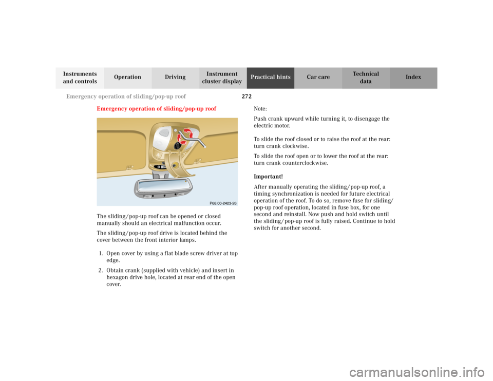
The sliding / pop-up roof can be opened or closed
manually should an electrical malfunction occur.
The sliding / pop-up roof drive is located behind the
cover between the front interior lamps.
1. Open cover by using a f lat blade screw driver at top
edge.
2. Obtain crank (supplied with vehicle) and insert in
hexagon drive hole, located at rear end of the open
cover.Note:
Push crank upward while turning it, to disengage the
electric motor.
To slide the roof closed or to raise the roof at the rear:
turn crank clockwise.
To slide the roof open or to lower the roof at the rear:
turn crank counterclockwise.
Important!
After manually operating the sliding / pop-up roof, a
timing synchronization is needed for future electrical
operation of the roof. To do so, remove fuse for sliding/
pop-up roof operation, located in fuse box, for one
second and reinstall. Now push and hold switch until
the sliding / pop-up roof is fully raised. Continue to hold
switch for another second.
RESETMODEMODE
Page 368 of 4133
DISABLING SYSTEM
Before proceeding, see AIR BAG SAFETY PRECAUTIONS . Record radio presets and obtain anti-theft
code. Turn ignition switch to OFF position and remove ignition key. If welding on vehicle, disconnect negative
battery cable and disconnect air bag control module.
ACTIVATING SYSTEM
Ensure ignition is off. Reconnect air bag system co mponents (if disconnected). Reconnect negative battery
cable. Perform See SYSTEM OPERATION CHECK
.
DISPOSAL PROCEDURES
Several situations may arise requiring so me form of disposal action, including:
Scrapping a vehicle containing a deployed air bag module and-or ETR.
Scrapping a vehicle with a live air bag module and-or ETR.
Disposal of a live but electrically faulty air bag module and-or ETR.
Disposal of a deployed air bag module and-or ETR.
DEPLOYED AIR BAG OR ETR
Deployed air bag module and-or ETR unit can be thrown away. None of its components are reusable. Deployed
air bag module is NOT classified as hazardous material.
SCRAPPED VEHICLE
1. Before proceeding, follow service precautions. See AIR BAG SAFETY PRECAUTIONS . Move
vehicle outdoors to a remote area, away from work shop and other personnel. Disconnect and shield
negative battery cable. Open al l vehicle windows and doors.
2. Ensure air bag module is secured to steering wheel, and passenger air bag is secured to dash. Ensure ETR
seat belt assemblies are secured to "B" pillars and all seat belt buckles are latched. Remove loose ob
jects
CAUTION: On CL500, open doors before
disconnecting battery. Opening doors
allows windows to automa tically lower thus preventing roof seal damage.
WARNING: An undeployed air bag module or ET R should never be disposed of
without first being deplo yed. See SCRAPPED VEHICLE
. If deployment is
not possible, contact vehicle manuf acturer for further instructions.
WARNING: An undeployed air bag m odule and-or ETR seat belt CANNOT be disposed
of without first being de ployed. If this is not possible through procedures
outlined below, contact vehicle ma nufacturer for further instructions.
Perform remote deployment outdoors . Keep personnel at least 20 feet
away.
2001 Mercedes-Benz ML320
2000-01 ACCESSORIES/SAFETY EQUIPMENT Merc edes-Benz - Air Bag Restraint Systems
me
Saturday, October 02, 2010 3:44:45 PMPage 4 © 2006 Mitchell Repair Information Company, LLC.
Page 503 of 4133
36
Tow-away protection
Te ch n ica l
data
Instruments
and controls Operation
Driving Instrument
cluster display Practical hints Car care Index
Tow-away alarm and glass breakage sensor
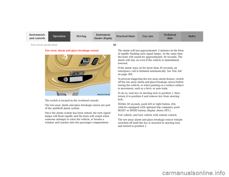
The switch is located in the overhead console.
The tow-away alarm and glass breakage sensor are part
of the antitheft alarm system.
Once the alarm system has been armed, the turn signal
lamps will flash rapidly and the horn will sound when
someone attempts to raise the vehicle, or breaks a
window and reaches into the passenger compartment. The alarm will last approximately 3 minutes in the form
of rapidly flashing turn signal lamps. At the same time
the horn will sound for approximately 30 seconds. The
alarm will stay on even if the vehicle is immediately
lowered.
If the alarm stays on for more than 20 seconds, an
emergency call is initiated automatically. See Tele Aid
on page 148.
To prevent triggering the tow-away alarm feature, switch
off the tow-away alarm and glass breakage sensor before
towing the vehicle, or when parking on a surface subject
to movement, such as a ferry or auto train.
To do so, turn key in steering lock to position 1, then
return it to position 0 and remove key from steering
lock.
Within 30 seconds, push left or right button. (On
vehicles equipped with optional trip computer, push
RESET or MODE button, display shows OFF.)
Exit vehicle, and lock vehicle with remote control.
The tow-away alarm and glass breakage sensor remain
switched off until the key is inserted in steering lock
and turned to position 1.
Page 517 of 4133
50
Restraint systems
Te ch n ica l
data
Instruments
and controls Operation
Driving Instrument
cluster display Practical hints Car care Index
Operation
The inertia reel stops the belt from unwinding during
sudden vehicle stops or when quickly pulling on the
belt. The locking function of the reel may be checked by
quickly pulling out the belt.
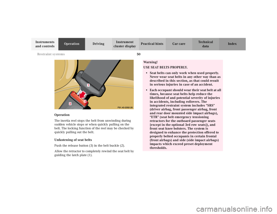
Unfastening of seat belts
Push the release button (3) in the belt buckle (2).
Allow the retractor to completely rewind the seat belt by
guiding the latch plate (1).
Wa r n i n g !
USE SEAT BELTS PROPERLY.• Seat belts can only work when used properly. Never wear seat belts in any other way than as
described in this section, as that could result
in serious injuries in case of an accident.• Each occupant should wear their seat belt at all
times, because seat belts help reduce the
likelihood of and potential severity of injuries
in accidents, including rollovers. The
integrated restraint system includes “SRS”
(driver airbag, front passenger airbag, front
and rear door mounted side impact airbags),
“ETR” (seat belt emergency tensioning
retractors for the outboard passenger seats
[except in the optional 3rd row seats]), and
front seat knee bolsters. The system is
designed to enhance the protection offered to
properly belted occupants in certain frontal
(front airbags) and side (side impact airbags)
impacts which exceed preset deployment
thresholds.
Page 521 of 4133
54
Restraint systems
Te ch n ica l
data
Instruments
and controls Operation
Driving Instrument
cluster display Practical hints Car care Index
Supplemental restraint system (SRS)
Airbags are intended as a supplement to seat belts.
Airbags alone cannot protect as well as airbags plus
seat belts in impacts for which the airbags were
designed to operate, and do not afford any protection
whatsoever in crashes for which the airbags are not
designed to deploy.
The SRS uses two crash severity levels (thresholds) to
activate either the Emergency Tensioning Retractor
(ETR) or front airbag or both. Activation depends on the
direction and severity of the impact exceeding the
preset thresholds and whether the seat belt is fastened. Seat belt fastened
• first threshold exceeded: ETR activates
• second threshold exceeded: airbag also activates
Seat belt not fastened
Front seats: • first threshold exceeded:
airbag activates, but not ETR
Rear outer seats: • first threshold exceeded:
ETR activates
Driver, front passenger and rear outer seat systems
operate independently of each other.
Page 522 of 4133
55
Restraint systems
Te ch n ica l
data
Instruments
and controls Operation
Driving Instrument
cluster display Practical hints Car care Index
Emergency tensioning retractor (ETR)
The seat belts for the outboard passenger seats (except
in the optional 3rd row seats) are equipped with
emergency tensioning retractors. These tensioning
retractors are located in each belt’s inertia reel and
become operationally ready with the key in steering
lock position 1 or 2.
The emergency tensioning retractors are designed to
activate only when the seat belts are fastened during
frontal impacts exceeding the first threshold of the SRS
and in rear impacts exceeding a preset severity level.
They remove slack from the belts in such a way that the
seat belts fit more snugly against the body restricting its
forward movement as much as possible. In cases of other frontal impacts, angled impacts, roll-
overs, certain side impacts, or other accidents without
sufficient frontal or rear impact forces, the emergency
tensioning retractors will not be activated. The driver
and passengers will then be protected by the fastened
seat belts and inertia reel in the usual manner.
For seat belt and emergency tensioning retractor see
page 63.
Page 524 of 4133
57
Restraint systems
Te ch n ica l
data
Instruments
and controls Operation
Driving Instrument
cluster display Practical hints Car care Index
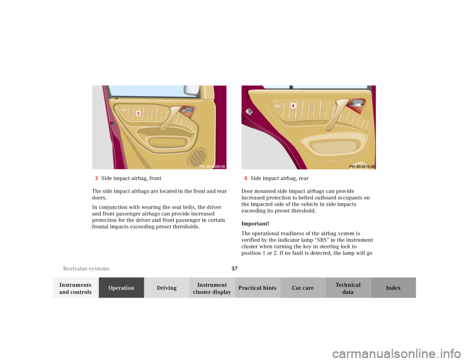
3
Side impact airbag, front
The side impact airbags are located in the front and rear
doors.
In conjunction with wearing the seat belts, the driver
and front passenger airbags can provide increased
protection for the driver and front passenger in certain
frontal impacts exceeding preset thresholds. 4
Side impact airbag, rear
Door mounted side impact airbags can provide
increased protection to belted outboard occupants on
the impacted side of the vehicle in side impacts
exceeding its preset threshold.
Important!
The operational readiness of the airbag system is
verified by the indicator lamp “SRS” in the instrument
cluster when turning the key in steering lock to
position 1 or 2. If no fault is detected, the lamp will go
3