1997 MERCEDES-BENZ ML320 buttons
[x] Cancel search: buttonsPage 1330 of 4133
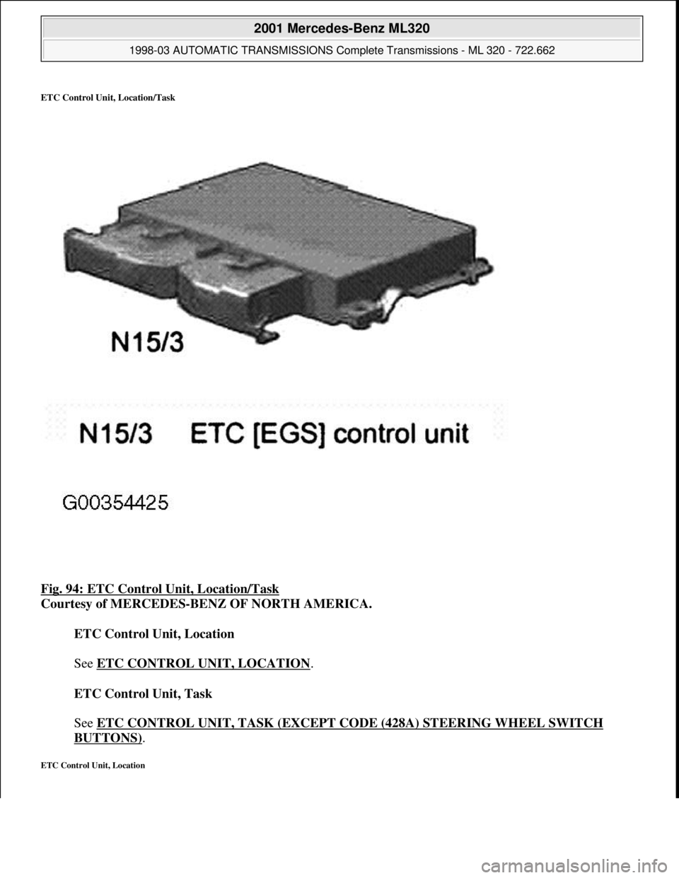
ETC Control Unit, Location/Task
Fig. 94: ETC Control Unit, Location/Task
Courtesy of MERCEDES-BENZ OF NORTH AMERICA.
ETC Control Unit, Location
See ETC CONTROL UNIT, LOCATION
.
ETC Control Unit, Task
See ETC CONTROL UNIT, TASK (EXCEPT CODE (428A) STEERING WHEEL SWITCH
BUTTONS).
ETC Control Unit, Location
2001 Mercedes-Benz ML320
1998-03 AUTOMATIC TRANSMISSIONS Complete Transmissions - ML 320 - 722.662
me
Saturday, October 02, 2010 3:15:27 PMPage 161 © 2006 Mitchell Repair Information Company, LLC.
Page 1554 of 4133
Program) appears on the radio and navigation unit display (A2/56).
Even when the RDS function is deactivated, the traffic station recognition and station following function remain
in operation (if activated). RDS alarm messages are still issued. In this case, CD playback or radio reception is
automatically interrupted.
2-tuner technology function
If interference occurs to reception while driving, the system attempts to receive the selected station on an
alternative frequency with the aid of the second (integrated) receiver and switch over when reception is better.
Moreover, the second radio receiver automatically generates a list of the receivable FM stations after switch-on,
and this list is continuously updated during operation. The stations contained in the list can be called up sorted
in alphabetical order with the station search buttons.
The station list is only available when the "RDS" function is activated.
At certain times, some radio channel programs are subdivided into regional programs.
Since the system automatically switches to an alternative frequency in the event of reception interference, this
can lead to a change in the regional program (not the radio network). If this is not desired, the regional program
function can be activated in the menu "REG". Switchover to an alternative frequency is then accomplished only
within the regional program.
FM antenna diversity function (models 209.3/4)
The antenna diversity function undertakes a reception-specific switchover between the FM antennas on the rear
window for model 209.3 (FM antennas of windshield for model 209.4). The function runs automatically and is
executed by the window antenna amplifier module 1 (A2/71) for model 209.3 (left antenna amplifier module
(A2/64) for model 209.4).
The radio tuner of the radio and navigation unit (A2/56) only generates the intermediate frequency (ZF) signal,
which serves as a reference to change the FM antenna for the window antenna amplifier module 1 (A2/71) on
model 209.3 (for model 209.4 left antenna amplifier module (A2/64)).
RDS Diversity/2-receiver technology function
The system consists of 2 FM receivers, a radio receiver and a search receiver. After turning on the radio system,
the search receiver automatically generates a list of FM stations received, which is continually updated during
operation.
Data such as reception quality, programs and alternative frequencies are stored. The audio receiver can therefore
switch over inaudibly to an alternative frequency. The list appears in alphabetical order when the "FM station
list" is called up. The stations which are displayed can be activated by selecting and confirming.
FM/AM antenna amplifier,
location/task/design/ functionModels 163, 168,
170, 208.4, 210.2
Models 208.3, 210 GF82.62-P-4101A
2001 Mercedes-Benz ML320
1998-2005 ACCESSORIES & BODY, CAB Electrical System - Body - 163 Chassis
me
Saturday, October 02, 2010 3:30:05 PMPage 59 © 2006 Mitchell Repair Information Company, LLC.
Page 1557 of 4133
manual station search is activated by actuating the "joystick "to left or right. The station search feature
stops at the next station found, even when the" joystick " continues to be actuated.
Automatic station search with scan function can be activated by pressing the multifunction " Scan " key.
Each station received in the frequency range is played for approx. 8 s This function is possible only in
the forward direction. When activated " Scan " appears inverted on the display.
Manual fine coordination
The frequency can be changed when the" joystick " is moved up or down.
Station selection from memory
For each frequency range (memory FM, AM ) there are 10 memory buttons available. Press button of
number block approx. 2 s to store a station. When a station is stored it is confirmed by an acoustic signal.
Any station stored previously is written over.
In the frequency range WB (weather forecast) 7 stations are preset. These stations can be called by
momentarily pressing the desired number of the number block.
Station selection with frequency input via number block Pressing the" *" button followed by actuation of
the number keys allows direct entry of the desired frequency. Undesired entries can be erased with the"
Clear " button.
Station selection from the FM or AM station list by pressing the multifunction key" List " all stored
stations in the momentary frequency range are listed. Exit station list by pressing FM or AM
multifunction key .
Automatic storage
The "Auto" multifunction key (when pressed for longer than 2 s ) starts automatic storage of the 10
strongest stations in the corresponding frequency range. The stations are stored according to the strength
of the received signals in decreasing order.
CD-PLAYER MODE, FUNCTION - GF82.60-P-2002B
MODELS 163, 168, 170, 203.0 /2 /7, 208, 209.3 /4, 210 with CODE (353) Audio 30 APS
CD's can be played on the CD drive integrated into the radio and navigation unit (A2/56) or with the CD player
with changer (in glove compartment) (A2/6). The audio data are transmitted over the Digital Data Bus (D2B).
The CD disk drive is a double-speed standard CD disk drive, which is suitable both for pla
ying back audio CDs
Volume/tone adjustments,
function GF82.60-P-2003GI
Antenna system (AS),
location of components GF82.62-P-0001-03D
FM/AM antenna amplifier,
location/purpose/
design/function GF82.62-P-4101A
2001 Mercedes-Benz ML320
1998-2005 ACCESSORIES & BODY, CAB Electrical System - Body - 163 Chassis
me
Saturday, October 02, 2010 3:30:05 PMPage 62 © 2006 Mitchell Repair Information Company, LLC.
Page 1584 of 4133
FERRY
TOLL
After calculation of the route, the navigation processor makes up a list of the streets along the route. This route
list is used for navigation. It can be displayed during navigation by pressing the "I" (INFO) and "RTE" (Route)
buttons.
Route updating
If the driver deviates from the calculated route, a new route list is automatically calculated by the navigation
processor. The current position and the direction of travel are taken into consideration, and the new route is
optimized accordingly. This is accomplished without any message on the display.
Circumventing traffic jams with "Traffic jam" menu key function
After a traffic jam is reported on traffic radio and before reaching the affected section, a route can be calculated
for driving around the traffic jam. For this purpose, activate the "Traffic jam" menu and enter the length of the
traffic jam including the distance to the start of the traffic jam.
The "Traffic jam" function is also available for Federal and State highways as well as for inner city areas.
Trips outside the digitized map area
If the vehicle leaves the digitized DVD map area (e.g. driving into a multi-level car park), then no route can be
calculated or updated. "OFF ROAD" appears on the display. Upon leaving the map boundary, the display "OFF
MAP" appears.
Destinations which lie outside of the digitalized map area cannot be taken into consideration on calculation of
the route.
ROUTE CALCULATION, FUNCTION - GF82.61-P-3011GI
MODEL 163 as of 1.9.01 with CODE (522) Modular control system (MCS) radio USA with CODE (357)
Navigation system - additional unit with CODE (818b) Single CD player - additional unit with CODE
(491) U.S. version
The route is calculated and updated continuously by the navigation processor after entering the destination on
the radio and navigation module (A2/56) It can only be calculated within the digitized map area. The
calculated route is the prerequisite of the guidance system .
Route calculation
The navigation processor calculates the route with the aid of the CD-ROMmap data, the entered destination
Destination guidance,
function GF82.61-P-3012D
2001 Mercedes-Benz ML320
1998-2005 ACCESSORIES & BODY, CAB Electrical System - Body - 163 Chassis
me
Saturday, October 02, 2010 3:30:05 PMPage 89 © 2006 Mitchell Repair Information Company, LLC.
Page 1596 of 4133
The display of the radios (A2) has 197 x 32 pixels. Texts are displayed in 3 lines.
After particular functions are called (e.g. navigation), the bottom line shows a variable inscription for the row of
buttons underneath (multifunction buttons). As a result the system can be operated very conveniently with a few
buttons, as the function which is activated when the button is operated, is shown in plain text (e.g. LANG,
ITEM, DYN, CLOCK etc.).
Audio signal output
The audio signals of the various sources (CD, voice output for navigation etc.) are processed by the radio (A2)
and amplified before output by the vehicle speakers.
On models 168, 170, 208 and 210 with the sound system (code 810) the audio signals are finally amplified
by the amplifier for the sound system (N40/3). For this, the audio source data (low-frequency signals) are
transmitted to the amplifier for the sound system (N40/3) via separate lines.
On models 163 and 209 the final amplification of the audio signal is performed by the sound amplifier
(A2/13). All the data are transmitted via the D2B.
Audio mute
An incoming phone call activates the audio mute function (a separate signal input exists on the radio (A2) for
this). When the audio mute function is activated, the current audio source (e.g. radio) is muted automatically.
Navigation processor, GPS control module and gyrosensor
The navigation processor is the central component of the navigation system.
It is integrated into the radio (A2) and from the incoming signals continuously calculates the location and once
the destination is entered calculates the route for navigation. The GPS receiver is integrated into the navigation
processor. It evaluates the satellite signals and calculates from them the vehicle position in degrees longitude
and latitude. Various GPS antennae are used to receive these signals depending on the vehicle model:
Model 163: telephone and GPS roof antenna (A2/49)
Models 168, 208.3, 210: GPS antenna (A2/49a2)
Models 170, 208.4: GPS rear antenna (A2/23a2)
Model 209: GPS antenna (A2/23)
Reception from at least 3 satellites is necessary for exact GPS position calculation. A free view of the sky is
required for this purpose.
The integrated gyrosensor continuously senses every change in direction of the vehicle. Evaluation of this data
is accomplished by the navigation processor.
Calibration of the gyrosensor is not required.
2001 Mercedes-Benz ML320
1998-2005 ACCESSORIES & BODY, CAB Electrical System - Body - 163 Chassis
me
Saturday, October 02, 2010 3:30:05 PMPage 101 © 2006 Mitchell Repair Information Company, LLC.
Page 1597 of 4133
DVD drive and DVD
The DVD drive of the radio (A2) reads data from the navigation DVD inserted and makes this available to the
navigation processor via the data bus inside the device.
Audio CDs can also be played.
The following are located on the navigation DVD:
Program data for the navigation computer
Voice segments for voice output
Map data.
A distinction is made between digitized and non-digitized areas within the DVD map area:
Villages, towns, roads, intersections and their attributes (e.g. one-way streets, no turns etc.) are recorded
in the digitized map area.
Included in the non-digitized areas are, for example company/private grounds, farms, small housing
estates, tracks across fields and areas between villages.
No data is available here.
Diagnosis interface (K-line) and fault management of D2B-components
During operation, the system stores all occurring faults in the nonvolatile memory. It is not possible to output
the fault via the display of the radio (A2).
The radio's (A2) fault management also includes the D2B-components connected. For this purpose, each D2B
component has its own DTC memory. The faults are transmitted from the corresponding components via the
D2B to the radio (A2) and can then be read out via the diagnosis interface
RADIO AND NAVIGATION MODULE, FUNCTION - GF82.61-P-4109-04GI
Processing button actuations
The control buttons and switches on the function keypad on the radio and navigation module (A2/56)are read
in via the I/O ports of the microcontroller and transferred to the central processor. Depending on the system
function the button actuations are processed in the central processor or relayed to the other system components
via the digital data bus ( D2B ) in form of a data telegram.
Graphic preparation and image output
The graphics subsystem handles the preparation and output of the operating displays. The operating displays are
output internally to the display by the graphic subsystem via the RGB output ( R =red, G =green, B =blue).
The RGB signal contains information and amplitudes of the three basic colors Red, G reen and Blue as well
2001 Mercedes-Benz ML320
1998-2005 ACCESSORIES & BODY, CAB Electrical System - Body - 163 Chassis
me
Saturday, October 02, 2010 3:30:05 PMPage 102 © 2006 Mitchell Repair Information Company, LLC.
Page 1634 of 4133
If a name is not available for the stored telephone number, the display is switched over and the
memory location and the telephone number are displayed.
By manually entering 1 or 2 numbers and subsequent actuation of the multifunction key" NAME " or
"NUM " the name stored under this memory location number or the stored telephone number are
indicated.
Pressing " SEND " button completes the desired connection. If no connection is to be completed, the
memory area can be exited by pressing the multifunction key" EXIT ".
Quick dial
When a one or two-digit number is entered and the " SEND " button is actuated the telephone number
stored under this memory location number is dialed.
By pressing and holding one of the number buttons 1 to 9 for more than 2 s the telephone number stored
under this memory location number is dialed. In this case it is not necessary to actuate the " SEND "
button.
Memory location functions 1 number is reserved for emergency !
Redialing
Pressing the" SEND " button without previously entering a telephone number calls up the last 5 selected
telephone numbers on the display. It is possible to select the desired telephone number by pressing the"
joystick " up or down. The connection is completed by actuating the" SEND " button. This area can be
exited by pressing the multifunction key" EXIT ".
Incoming calls
During an incoming call all other audio sources are set to mute and "CALL " appears on the display. The
call can be accepted by pressing the " SEND " button or terminated by pressing the" END " button.
During a call it is possible to continue dialing, e.g. enter a code number for an answering machine.
CASSETTE MODE, FUNCTION - GF82.85-P-2010GI
MODEL 163 as of 1.9.01 with CODE (522) Modular control system (MCS) radio USA with CODE (357)
Navigation system - additional unit with CODE (818b) Single CD player - additional unit with CODE
(491) U.S. version
GPS roof
antenna/telephone,
location/purpose/
design/function GF82.70-P-
4111A
2001 Mercedes-Benz ML320
1998-2005 ACCESSORIES & BODY, CAB Electrical System - Body - 163 Chassis
me
Saturday, October 02, 2010 3:30:06 PMPage 139 © 2006 Mitchell Repair Information Company, LLC.
Page 1676 of 4133
The personal symbols on the map are not updated during active guidance.
Voice control does not react to commands
Occasionally no sound (duration approx. 1 second).
TV screen switches off when standing still
After switching on CD player plays CD1/track 1 instead of title played last
No message when CD magazine sticks during ejection
Wavy interference in navigation display when TV picture is switched off (as if station is not correctly
received)
TCS icons are occasionally not displayed on the map with active dynamic guidance
Telephone book is not activated.
COMAND: A 208 820 40 89, A 210 820 54 89, A 163 820 14 89
Error patterns:
Increased quiescent current.
The personal symbols on the map are not updated during active guidance.
Voice control does not react to commands
No message when CD magazine sticks during ejection
TCS cannot be activated sporadically.
Time in instrument cluster and COMAND differs approx. 1-2 seconds.
COMAND signals CD reading error without any obvious cause
PERFORMING SOFTWARE DOWNLOAD - AF82.85-P-6000-04A
COMAND 2.0-ECE / 2.5-ECE - Perform software download of CD:
Do not start vehicle during download, do not cause other voltage drops in the vehicle electrical system, do
not remove CD and do not switch off unit! (Unit will be damaged!)
In the case of erroneous operation of the download control module, the download starts again or is terminated if
the old software has not been erased previously.
1. Switch off ignition.
2. Remove navigation CD and insert download CD.
3. Switch off control module.
4. After a waiting time of min. 5 s and with buttons * and # pressed simultaneously, switch on unit.
The menu "Service download of CD" appears with menu points "Control module" and "Termination".
5. Select "Start control module" with right knob
2001 Mercedes-Benz ML320
1998-2005 ACCESSORIES & BODY, CAB Electrical System - Body - 163 Chassis
me
Saturday, October 02, 2010 3:30:07 PMPage 181 © 2006 Mitchell Repair Information Company, LLC.