Page 3252 of 4133

Two main objectives are pursued in heating operation:
rapid heating and even control of in-car temperature
good visibility through windshield and front side windows
In the starting phase the headroom temperature is deliberately increased, in order to meet the passengers' initial
increased heat requirements. The temperature and the duration depend on the outside temperature and the in-car
temperature.
As far as good visibility is concerned, special control measures to accelerate defrosting of the windows are
taken during the starting phase, depending on the ambient conditions.
In closed-loop operation the footwell vents are mainly used to control the in-car temperature. The center nozzle
is fully closed. The defrosting control measures are reduced.
Cooling operation
During cooling operation the objective is to cool the interior rapidly and evenly control the temperature.
Window fogging is not usually a problem during maximum cooling operation and therefore does not require
special measures.
In the starting phase the headroom temperature is deliberately reduced. The temperature and the duration
depend on the outside temperature and the in-car temperature.
Furthermore, the cooling capacity can be reduced during subsequent operation since continuous partial
recirculating air operation can be achieved.
In closed-loop operation the center nozzles are mainly used to control the in-car temperature.
Bi-level operation (2-level operation)
In bi-level operation the temperature of the interior is controlled by a combination of the footwell nozzles and
the center nozzles.
The objective is to create stratification , which gives the passengers warm feet and a cooler head .
The air distribution shifts in the direction of heating or cooling operation depending on the controller status
trend.
Rear compartment ventilation
The rear compartment nozzles are supplied with temperature-controlled air by the front compartment automatic
air conditioning. The rear compartment nozzle outlet temperature can therefore not be separately controlled.
The air quantity and the air distribution are available as adjustable parameters. The passengers in the rear can
control the ventilation themselves usin
g appropriate buttons.
2001 Mercedes-Benz ML320
1998-2005 HVAC Climate Control - 163 Chassis
me
Saturday, October 02, 2010 3:23:14 PMPage 8 © 2006 Mitchell Repair Information Company, LLC.
Page 3520 of 4133

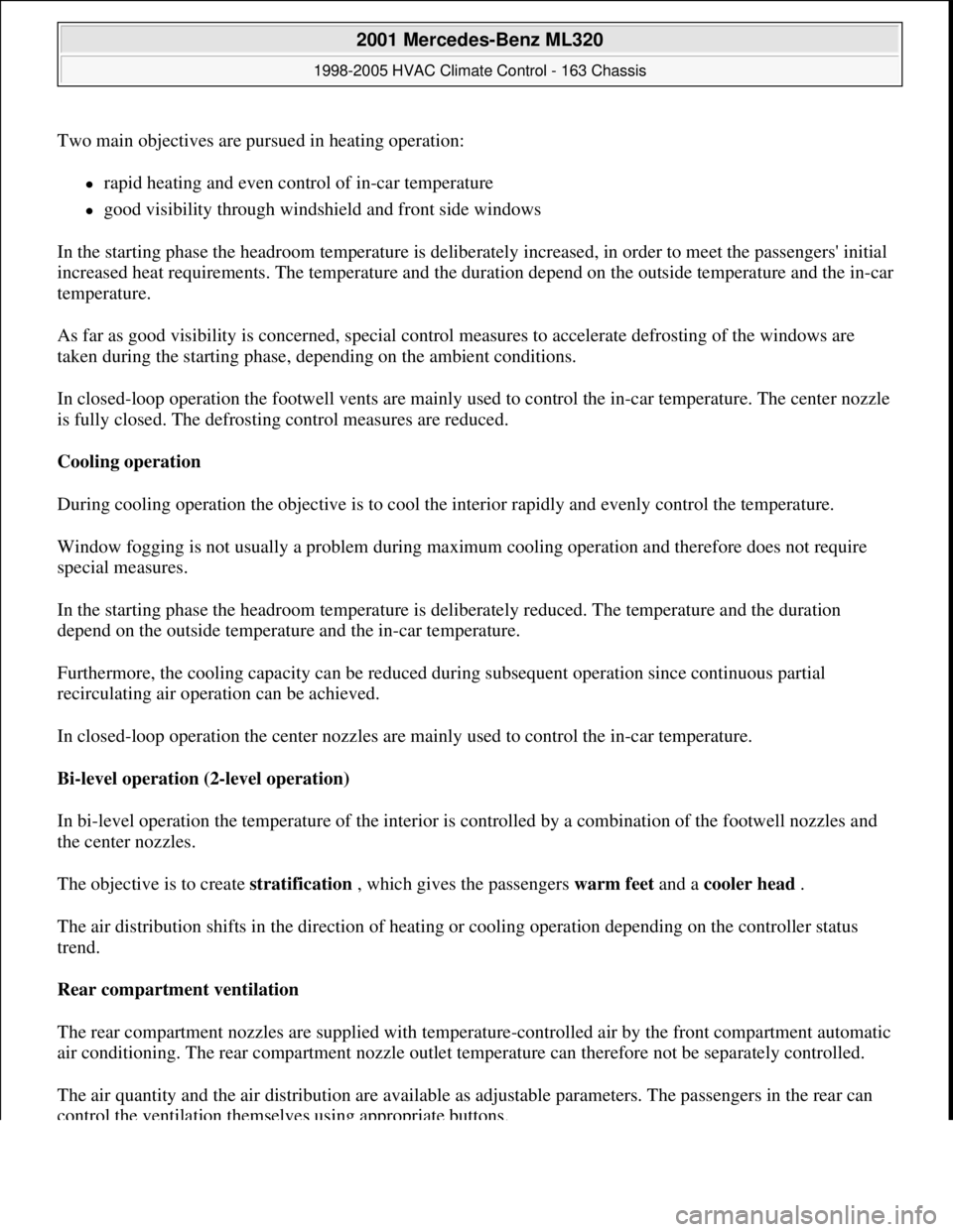
Shown on model 230
Fig. 1: Identifying Garage Door Opener Buttons
- Shown On Model 230
Garage door opener, function
The garage door opener consists of an intelligent radio remote control with three transmitter buttons capable of
learning. Various receivers for opening and closing systems and doors can be activated with the three buttons,
garage door opener button 1 (A67s1), garage door opener button 2 (A67s2) or garage door opener button 3
(A67s3).
Program remote control
Function requirements:
Term. 15R or 15 ON
Press and hold down garage door opener button 1 (A67s1), garage door opener button 2 (A67s2) or
garage door opener button 3 (A67s3).
The garage door opener indicator lamp (A67e4) starts flashing (frequency 1 Hz).
Continue to actuate garage door opener button 1 (A67s1), garage door opener button 2 (A67s2) or garage
door opener button 3 (A67s3) and hold garage door remote control with transmit button pressed for t < 90
s.
After successful programming, the garage door opener indicator lamp (A67e4) flashes rapidly (f = 5.5
Hz) for approx. 10 s.
Release the two transmit buttons and program additional transmitters as required.
Time switch-off
To protect the vehicle battery, the transmitter unit switches off the learn-in mode when programming is not
accomplished within approx. 100 s.
Transmitter mode
2001 Mercedes-Benz ML320
1998-2005 ACCESSORIES & BODY, CAB Interior Equipment - 163 Chassis
me
Saturday, October 02, 2010 3:35:21 PMPage 2 © 2006 Mitchell Repair Information Company, LLC.
Page 3522 of 4133

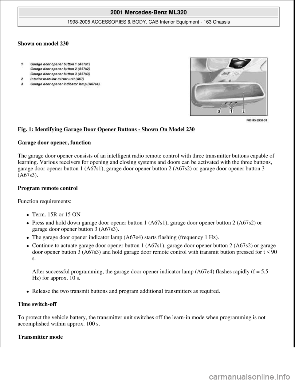
Fig. 2: Identifying Garage Door Opener Transmitter Keys
Illustrated on model 230
GARAGE DOOR OPENER TRANSMITTER, LOCATION - GF68.05-P-1100-01C
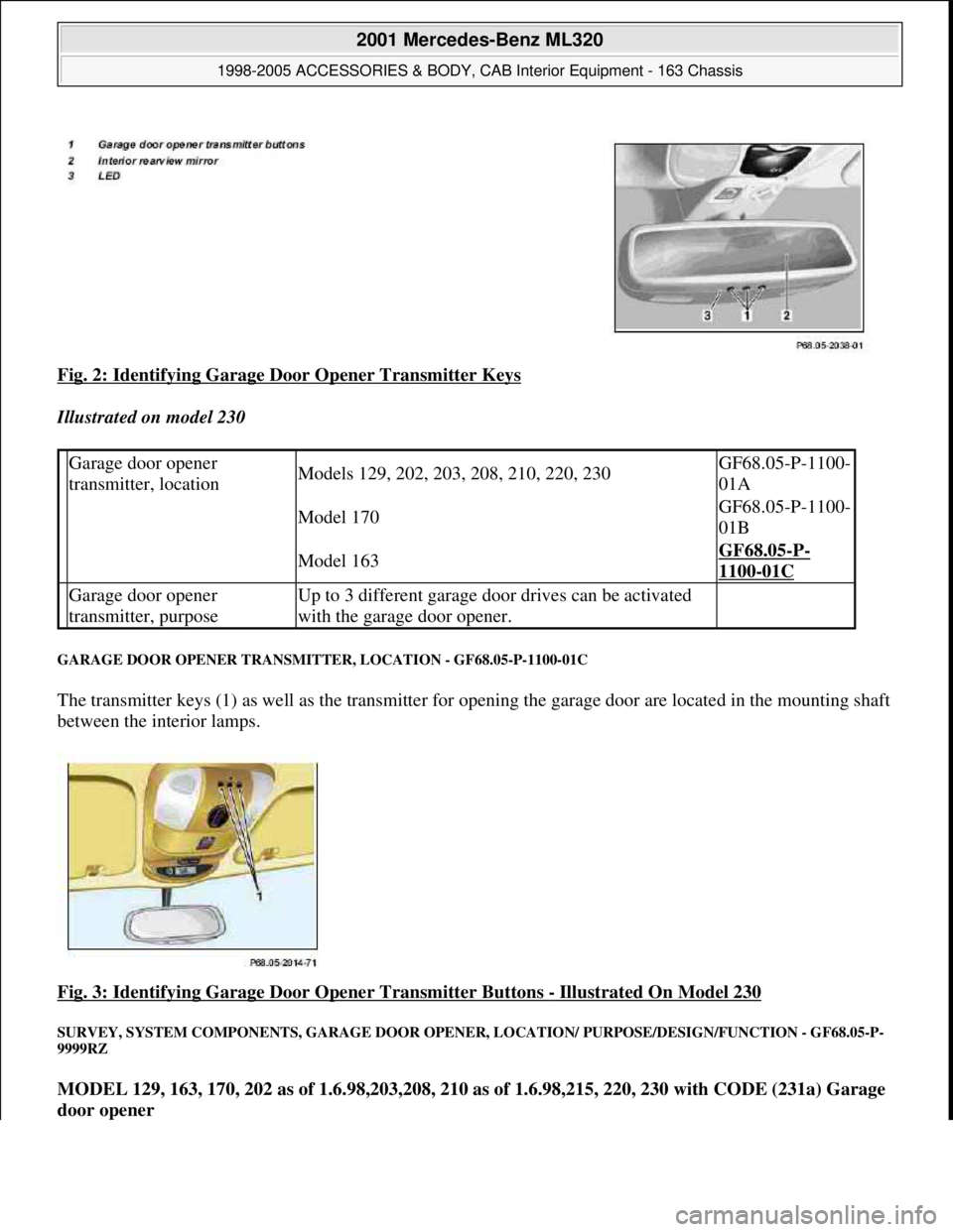
The transmitter keys (1) as well as the transmitter for opening the garage door are located in the mounting shaft
between the interior lamps.
Fig. 3: Identifying Garage Door Opener Transmitter Buttons
- Illustrated On Model 230
SURVEY, SYSTEM COMPONENTS, GARAGE DOOR OPENER, LOCATION/ PURPOSE/DESIGN/FUNCTION - GF68.05-P-
9999RZ
MODEL 129, 163, 170, 202 as of 1.6.98,203,208, 210 as of 1.6.98,215, 220, 230 with CODE (231a) Garage
door opener
Garage door opener
transmitter, locationModels 129, 202, 203, 208, 210, 220, 230GF68.05-P-1100-
01A
Model 170GF68.05-P-1100-
01B
Model 163GF68.05-P-
1100-01C
Garage door opener
transmitter, purposeUp to 3 different garage door drives can be activated
with the garage door opener.
2001 Mercedes-Benz ML320
1998-2005 ACCESSORIES & BODY, CAB Interior Equipment - 163 Chassis
me
Saturday, October 02, 2010 3:35:21 PMPage 4 © 2006 Mitchell Repair Information Company, LLC.
Page 3527 of 4133

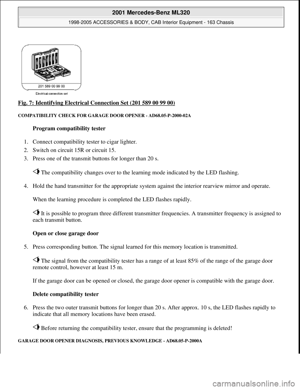
Fig. 7: Identifying Electrical Connection Set (201 589 00 99 00)
COMPATIBILITY CHECK FOR GARAGE DOOR OPENER - AD68.05-P-2000-02A
Program compatibility tester
1. Connect compatibility tester to cigar lighter.
2. Switch on circuit 15R or circuit 15.
3. Press one of the transmit buttons for longer than 20 s.
The compatibility changes over to the learning mode indicated by the LED flashing.
4. Hold the hand transmitter for the appropriate system against the interior rearview mirror and operate.
When the learning procedure is completed the LED flashes rapidly.
It is possible to program three different transmitter frequencies. A transmitter frequency is assigned to
each transmit button.
Open or close garage door
5. Press corresponding button. The signal learned for this memory location is transmitted.
The signal from the compatibility tester has a range of at least 85% of the range of the garage door
remote control, however at least 15 m.
If the garage door can be opened or closed, the garage door opener is compatible with the garage door.
Delete compatibility tester
6. Press the two outer transmit buttons for longer than 20 s. After approx. 10 s, the LED flashes rapidly to
indicate that all memory locations have been erased.
Before returning the compatibility tester, ensure that the programming is deleted!
GARAGE DOOR OPENER DIAGNOSIS, PREVIOUS KNOWLEDGE - AD68.05-P-2000A
2001 Mercedes-Benz ML320
1998-2005 ACCESSORIES & BODY, CAB Interior Equipment - 163 Chassis
me
Saturday, October 02, 2010 3:35:21 PMPage 9 © 2006 Mitchell Repair Information Company, LLC.