1997 MERCEDES-BENZ ML320 rear main seal
[x] Cancel search: rear main sealPage 1358 of 4133

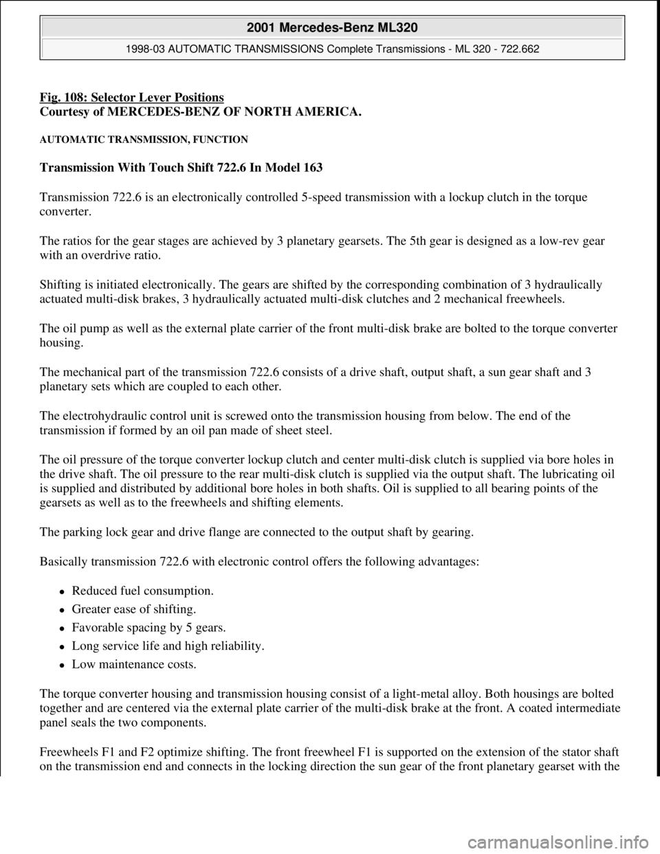
Fig. 108: Selector Lever Positions
Courtesy of MERCEDES-BENZ OF NORTH AMERICA.
AUTOMATIC TRANSMISSION, FUNCTION
Transmission With Touch Shift 722.6 In Model 163
Transmission 722.6 is an electronically controlled 5-speed transmission with a lockup clutch in the torque
converter.
The ratios for the gear stages are achieved by 3 planetary gearsets. The 5th gear is designed as a low-rev gear
with an overdrive ratio.
Shifting is initiated electronically. The gears are shifted by the corresponding combination of 3 hydraulically
actuated multi-disk brakes, 3 hydraulically actuated multi-disk clutches and 2 mechanical freewheels.
The oil pump as well as the external plate carrier of the front multi-disk brake are bolted to the torque converter
housing.
The mechanical part of the transmission 722.6 consists of a drive shaft, output shaft, a sun gear shaft and 3
planetary sets which are coupled to each other.
The electrohydraulic control unit is screwed onto the transmission housing from below. The end of the
transmission if formed by an oil pan made of sheet steel.
The oil pressure of the torque converter lockup clutch and center multi-disk clutch is supplied via bore holes in
the drive shaft. The oil pressure to the rear multi-disk clutch is supplied via the output shaft. The lubricating oil
is supplied and distributed by additional bore holes in both shafts. Oil is supplied to all bearing points of the
gearsets as well as to the freewheels and shifting elements.
The parking lock gear and drive flange are connected to the output shaft by gearing.
Basically transmission 722.6 with electronic control offers the following advantages:
Reduced fuel consumption.
Greater ease of shifting.
Favorable spacing by 5 gears.
Long service life and high reliability.
Low maintenance costs.
The torque converter housing and transmission housing consist of a light-metal alloy. Both housings are bolted
together and are centered via the external plate carrier of the multi-disk brake at the front. A coated intermediate
panel seals the two components.
Freewheels F1 and F2 optimize shifting. The front freewheel F1 is supported on the extension of the stator shaft
on the transmission end and connects in the lockin
g direction the sun gear of the front planetary gearset with the
2001 Mercedes-Benz ML320
1998-03 AUTOMATIC TRANSMISSIONS Complete Transmissions - ML 320 - 722.662
me
Saturday, October 02, 2010 3:15:28 PMPage 189 © 2006 Mitchell Repair Information Company, LLC.
Page 2609 of 4133

Remove, Install
Danger!
Risk of explosion
from fuel igniting,
risk of
poisoning
from inhaling and swallowing fuel
as well as
risk of injury
to eyes and skin
from contact with fuel.
Fire, sparks, open flames or smoking
forbidden.
Pour fuels only into suitable and appropriately
marked containers.
Wear protective clothing when handling fuel.
AS47.00-Z-0001-01A
1
Drain fuel tank
Via fuel pump. NOT for model 163.113/128.
AR47.10-P-4001GH
If fuel pump faulty, and model 163.113/128.
AR47.10-P-4000GH
*BF47.10-P-1001-01A
2
Unscrew filler cap (2) and detach from filler
cap attachment (4)
3.1
Remove left seat of 3rd seat row
If installed. See owner's manual
4
Unclip cover of left-hand side panel (1)
5.1
Detach fuel lines of expansion reservoir and
separate from filler neck
As of VIN A289565. NOT for model
163.113/128.
6
Detach fuel filler neck from guide funnel
Installation:
Check O-ring and replace if
necessary. Ensure that the bayonet-lock
remains above
the pressure sensor.
Ensure it is correctly located when installed.
Open bayonet lock (3) to do this.
7
Pull filler neck through toward interior
Screw on cap again in order to avoid fuel
flowing out.
8.1
Remove fuel tank pressure sensor (B4/3)
Only USA version
AR47.10-P-8022GH
9.1
Detach bolted connection of fuel tank filler
neck/ground (X36/4) from filler neck
NOT for model 163.113/128.
10.1
Cut cable strap for retaining clips of fuel lines
at filler neck and remove retaining clips
As of VIN A289565. NOT for model
163.113/128.
Danger!
Risk of fatal accident
from vehicle slipping
or toppling off the lift platform
Align vehicle between the columns of lifting
platform and position the four support plates
below the support strongpoints specified by
the vehicle manufacturer.
AS00.00-Z-0010-01A
11
Place the vehicle on lifting platform
AR00.60-P-1000GH
12
Separate rubber seal (5) from underside of
vehicle and remove filler neck from interior
Do not damage fuel lines at filler neck.
13
Remove left rear wheel
e
Removing and installing wheels, rotating if
necessary
AP40.10-P-4050GH
14
Remove spare wheel and spare wheel carrier
complete
NOT in the case of spare wheel
holder/spare wheel, code 849.
15
Cut a large safety cable strap for filler neck at
bracket on longitudinal frame member
16
Remove bracket from longitudinal frame
member
17
Disconnect connection for regeneration (77/2)
and fresh air connection (77/4) on activated
charcoal canister (77)
Installation
: Connect up lines as per
connection diagram:
#
Engine 111
AR47.30-P-8212-01GJ
Engines 112, 113
AR47.30-P-8212-01GI
Engines 112, 113 version
I
AR47.30-P-8212-01GH
Charcoal canister and fuel tank form a
single unit.
NOT for model 163.113/128.
18
Detach vent hose
At rear differential to rear of activated
charcoal reservoir.
19
Remove rear exhaust system heat shield.
Do not damage boot at rear axle shaft.
20
Disconnect rear propeller shaft at differential
Installation:
Install new self-locking bolts.
Tie up propeller shaft e.g. using welding
wire
Heat bolts with hot air fan to facilitate
removing. Mark propeller shaft and differential
gear flange for correct installed position.
*BA41.10-P-1002-01C
Copyright DaimlerChrysler AG 28.05.2006 CD-Ausgabe G/10/04 . This WIS print-out will not be recorde
d by Modification services.
Page 2
Page 2656 of 4133

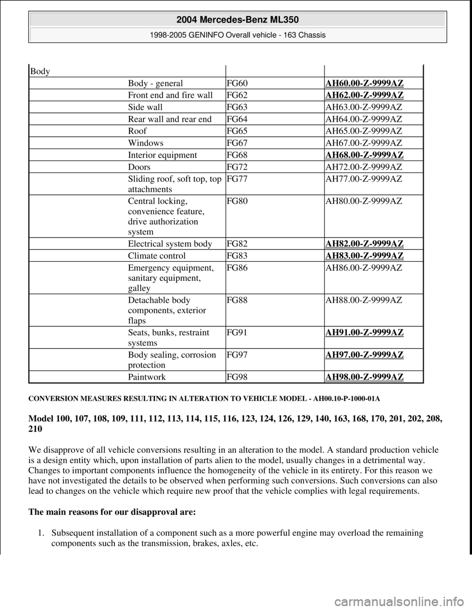
CONVERSION MEASURES RESULTING IN ALTERATION TO VEHICLE MODEL - AH00.10-P-1000-01A
Model 100, 107, 108, 109, 111, 112, 113, 114, 115, 116, 123, 124, 126, 129, 140, 163, 168, 170, 201, 202, 208,
210
We disapprove of all vehicle conversions resulting in an alteration to the model. A standard production vehicle
is a design entity which, upon installation of parts alien to the model, usually changes in a detrimental way.
Changes to important components influence the homogeneity of the vehicle in its entirety. For this reason we
have not investigated the details to be observed when performing such conversions. Such conversions can also
lead to changes on the vehicle which require new proof that the vehicle complies with legal requirements.
The main reasons for our disapproval are:
1. Subsequent installation of a component such as a more powerful engine may overload the remaining
components such as the transmission, brakes, axles, etc.
Body
Body - generalFG60AH60.00-Z-9999AZ
Front end and fire wallFG62AH62.00-Z-9999AZ
Side wallFG63AH63.00-Z-9999AZ
Rear wall and rear endFG64AH64.00-Z-9999AZ
RoofFG65AH65.00-Z-9999AZ
WindowsFG67AH67.00-Z-9999AZ
Interior equipmentFG68AH68.00-Z-9999AZ
DoorsFG72AH72.00-Z-9999AZ
Sliding roof, soft top, top
attachmentsFG77AH77.00-Z-9999AZ
Central locking,
convenience feature,
drive authorization
systemFG80AH80.00-Z-9999AZ
Electrical system bodyFG82AH82.00-Z-9999AZ
Climate controlFG83AH83.00-Z-9999AZ
Emergency equipment,
sanitary equipment,
galleyFG86AH86.00-Z-9999AZ
Detachable body
components, exterior
flapsFG88AH88.00-Z-9999AZ
Seats, bunks, restraint
systemsFG91AH91.00-Z-9999AZ
Body sealing, corrosion
protectionFG97AH97.00-Z-9999AZ
PaintworkFG98AH98.00-Z-9999AZ
2004 Mercedes-Benz ML350
1998-2005 GENINFO Overall vehicle - 163 Chassis
me
Saturday, October 02, 2010 3:47:44 PMPage 11 © 2006 Mitchell Repair Information Company, LLC.
Page 3983 of 4133

10
Remove edge guard for tilting/sliding roof
cutout
11
Release upper right B-pillar paneling
12
Remove covers at lower rear seat
Do NOT remove center cover for lower
40% seat. Do NOT reinstall curtain on 60%
front bench seat.
f
Remove and install cover on bottom of rear
seat
AR91.12-P-1100GH
13
Release side shade at the 60% bench
Fold shade upward so that the working
area is not obstructed.
14
Remove 40% rear seat
f
Remove and install bench
AR91.12-P-1010GI
Torx bit set
*000589011000
Install
15
Retrofit central interface module (1)
AZ82.60-P-0004-01A
16
Insert antenna cable for FM modulator (6) into
vehicle antenna cable (7)
17
Cover connector with self-adhesive foamed
material (8)
18
Plug remaining antenna cable of FM
modulator (9) into radio
19
Install radio (A2)
f
Remove/install radio
AR82.60-P-7502EA
20
Retrofit video monitor (2) and wiring harness
of video monitor (C)
With
glass version of electric sliding/tilting
roof, code 414a.
AZ82.60-P-0004-02A
Except
glass version of electric
sliding/tilting roof, code 414a.
AZ82.60-P-0004-02B
21
Secure upper right B-pillar paneling
Ensure that the lugs of the seat belt height
adjustment are located correctly in the recess
clearance of the paneling.
22
Install right front handle
23
Install right sun visor
f
Remove/install sun visor
AR68.60-P-5480GH
24
Install right front A-pillar cover
f
Remove/install paneling on A-pillar
AR68.30-P-4050GH
25
Re-secure upper area of rubber door seal
26
Route wiring harness of video/DVD player
(B), additional interface module (4) and wiring
harness of video monitor (C) later
Up to VIN A289564, X754619.
AZ82.60-P-0004-03A
As of VIN A289565, X754620.
AZ82.60-P-0004-03B
27
Retrofit auxiliary interface module (4) in
center console
Up to VIN A289564, X754619.
AZ82.60-P-0004-04A
As of VIN A289565, X754620.
AZ82.60-P-0004-04B
28
Install center console insulating mat
29
Install center console
f
Remove/install center console
AR68.20-P-2000GH
30.1
Plug in plug of additional interface module
and secure the wiring harness of the
additional interface module (10) to the clip
(11) together with the wiring harness of the
rear power windows in the center console
Up to VIN A289564, X754619.
30.2
Insert auxiliary interface module (13)
connector and route between center console
mount (14) and center console.
As of VIN A289565, X754620.
31.1
Secure auxiliary interface module plug in the
left rear corner of the ashtray housing using
self-adhesive foamed material (12)
Up to VIN A289564, X754619.
32
Open ashtray and cup holder and close to
check correct function
33
Attach side shade of the 60% bench
34.1
Retrofit video player (3)
AZ82.60-P-0004-05A
*BA91.12-P-1005-03A
*BA91.12-P-1008-03A
34.2
Retrofit DVD player
AZ82.60-P-0005-01GH
35
Install 40% rear seat
f
Remove and install bench
AR91.12-P-1010GI
Torx bit set
*000589011000
Copyright DaimlerChrysler AG 09.05.2006 CD-Ausgabe G/10/04 . This WIS print-out will not be recorde
d by Modification services.
Page 2