1997 MERCEDES-BENZ ML320 buttons
[x] Cancel search: buttonsPage 1781 of 4133
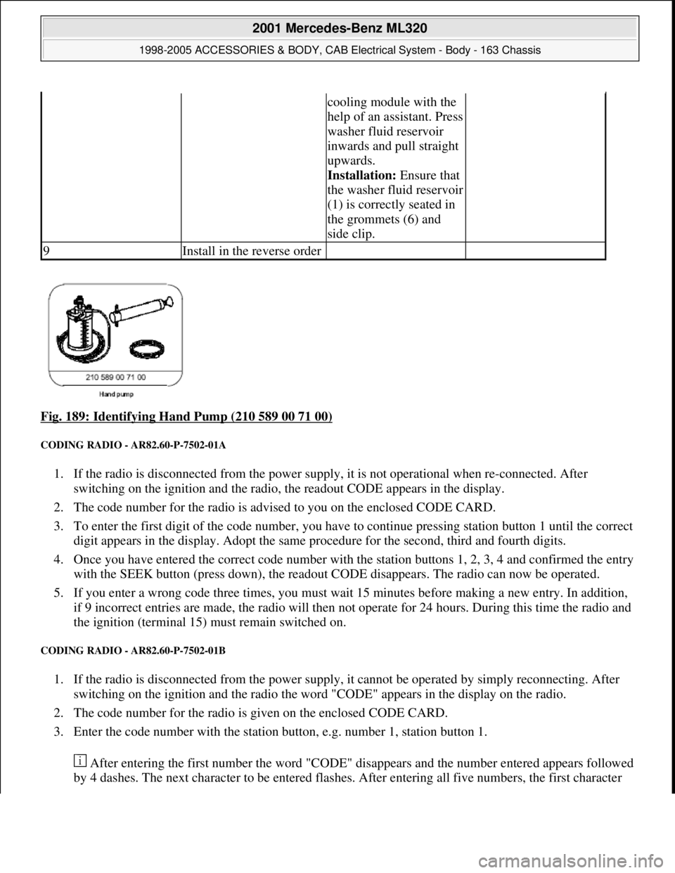
Fig. 189: Identifying Hand Pump (210 589 00 71 00)
CODING RADIO - AR82.60-P-7502-01A
1. If the radio is disconnected from the power supply, it is not operational when re-connected. After
switching on the ignition and the radio, the readout CODE appears in the display.
2. The code number for the radio is advised to you on the enclosed CODE CARD.
3. To enter the first digit of the code number, you have to continue pressing station button 1 until the correct
digit appears in the display. Adopt the same procedure for the second, third and fourth digits.
4. Once you have entered the correct code number with the station buttons 1, 2, 3, 4 and confirmed the entry
with the SEEK button (press down), the readout CODE disappears. The radio can now be operated.
5. If you enter a wrong code three times, you must wait 15 minutes before making a new entry. In addition,
if 9 incorrect entries are made, the radio will then not operate for 24 hours. During this time the radio and
the ignition (terminal 15) must remain switched on.
CODING RADIO - AR82.60-P-7502-01B
1. If the radio is disconnected from the power supply, it cannot be operated by simply reconnecting. After
switching on the ignition and the radio the word "CODE" appears in the display on the radio.
2. The code number for the radio is given on the enclosed CODE CARD.
3. Enter the code number with the station button, e.g. number 1, station button 1.
After entering the first number the word "CODE" disappears and the number entered appears followed
by 4 dashes. The next character to be entered flashes. After entering all five numbers, the first character
cooling module with the
help of an assistant. Press
washer fluid reservoir
inwards and pull straight
upwards.
Installation: Ensure that
the washer fluid reservoir
(1) is correctly seated in
the grommets (6) and
side clip.
9Install in the reverse order
2001 Mercedes-Benz ML320
1998-2005 ACCESSORIES & BODY, CAB Electrical System - Body - 163 Chassis
me
Saturday, October 02, 2010 3:30:09 PMPage 286 © 2006 Mitchell Repair Information Company, LLC.
Page 1782 of 4133
starts flashing again. In this state the code number can be written over as frequently as desired. A
correction can be made only by entering the complete code number again.
4. Confirm code number:
Press TUNE, AUTO/SEEK or SC button. The radio automatically switches on and indicates the radio
station or frequency stored with station button 1.
5. If an incorrect code number is entered and confirmed, the word "CODE" appears again on the display. If
an incorrect code is entered three times the word "WAIT" appears on the display and the radio locks up
for approx. 10 min. If the code is entered incorrectly three times again the radio locks up again for 10
min. Three more incorrect entries (a total of 9 incorrect attempts) increase the lock-up time to 60 min.
Another three incorrect entries lock up the radio for another 60 min.
The waiting time runs only when the radio is switched on.
CODING RADIO - AR82.60-P-7502-01GH
1. If the power supply to the radio is interrupted the radio will not operate when reconnected. After
switching on the ignition the word "CODE" appears on the radio display.
2. The code number for this radio is given on the included code card.
3. Enter the code number with the station buttons, e.g. number 1 = station button 1..
4. After entering the first digit the word "CODE" disappears and the number entered is displayed followed
by four dashes. Enter the next numbers with the corresponding station buttons. After entering the five
digit code number compare the code number with the number on the display. At this point the code
number can be written over as frequently as necessary for correction. If the wrong code number has been
entered, enter the entire code number again.
5. Confirm entry of correct code number with " < " or " > " button.
6. If the wrong code number has been entered and confirmed the word "CODE" appears again on the display
and the code must be entered again.
7. After entering the code incorrectly three times the word "WAIT" appears on the display and the radio is
disabled for approx. 10 minutes. After entering the incorrect code three times again the radio is disabled
for approx. 60 minutes.
The disable time runs down only with the radio switched off.
REMOVE/INSTALL RADIO - AR82.60-P-7502EA
MODEL 129 with single-block unit, 2nd generation two-component unit control element and MB radios
MODEL 163 with CODE (257) Hi-Line radio with CODE (259) Premium radio with Bose sound system
with CODE (352) COMAND operating and display system with CODE (353) Audio 30 APS with CODE
(357) Navigation system - additional unit with CODE (522) Modular control system (MCS) radio USA
with CODE (750) MB Audio 30 RDS radio with CODE (752) Becker Mexico 2000 radio with traffic news
decoder with CODE (753) MB Audio 30 RDS radio with CODE (756) MB Audio 10 RDS radio with CD
compartment
2001 Mercedes-Benz ML320
1998-2005 ACCESSORIES & BODY, CAB Electrical System - Body - 163 Chassis
me
Saturday, October 02, 2010 3:30:09 PMPage 287 © 2006 Mitchell Repair Information Company, LLC.
Page 1831 of 4133
(min. 60°), drive another
300 meters straight ahead
and then turn again, etc.
It makes no difference for
the calibration if the course
of the road does not allow
the vehicle to be driven the
specified route straight
ahead or to turn min. 60°.
This only increases the
length of the route to be
driven. Calibration is
completed when the location
is indicated in the AUDIO
mode (without active
objective guidance) when
the INFO button is pressed.
However, the location
can only be displayed when
the vehicle is driven on a
digitized road.
11Perform test driveCall up navigation menu by
pressing the NAV
multifunction button.
Enter destination (see
operating instructions) and
drive to destination.
Start-up stepAction on keypadFeedback on display
Accelerated start-up
1Insert navigation CDLoading time can take
several minutes
2Navigation menuCall navigation menu by
pressing NAV buttonLANGUAGE POS
TIME WHEEL
3Call default calibration
values Select the menu
"ADDRESS ENTRY" b
y
turning right knob (10)
and confirm by pressing
knob (10). Press
multifunction buttons 2
and 7 one after another
and then release
simultaneously. Press
multifunction button
KAL.
CAL
Select the menu Vehicle menu appears
2001 Mercedes-Benz ML320
1998-2005 ACCESSORIES & BODY, CAB Electrical System - Body - 163 Chassis
me
Saturday, October 02, 2010 3:30:11 PMPage 336 © 2006 Mitchell Repair Information Company, LLC.
Page 1901 of 4133
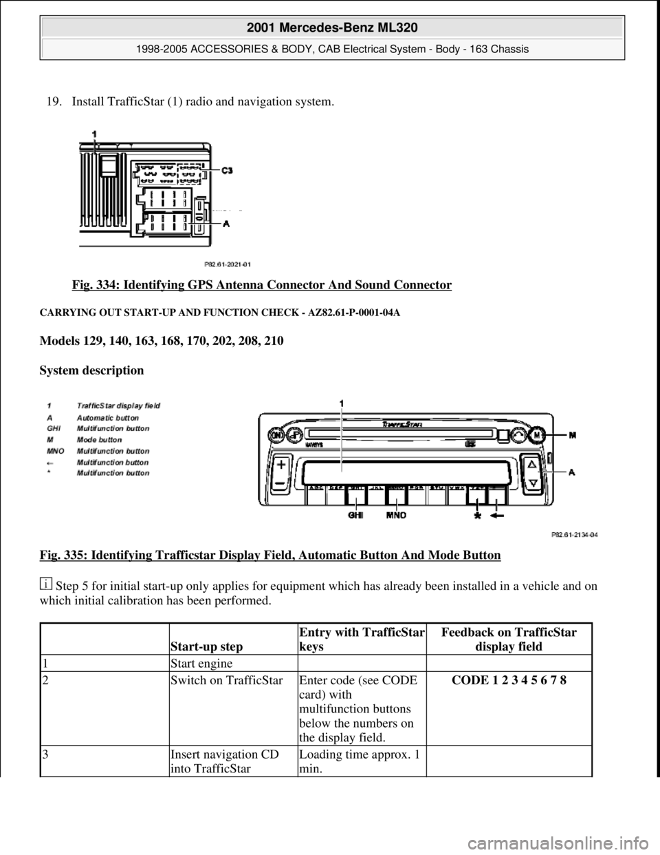
19. Install TrafficStar (1) ra dio and navigation system.
Fig. 334: Identifying GPS Antenna Connector And Sound Connector
CARRYING OUT START-UP AND FU NCTION CHECK - AZ82.61-P-0001-04A
Models 129, 140, 163, 168, 170, 202, 208, 210
System description
Fig. 335: Identifying Trafficstar Display Fi eld, Automatic Button And Mode Button
Step 5 for initial start-up only applies for equipment which has already been installed in a vehicle and on
which initial calibration has been performed.
Start-up step
Entry with TrafficStar
keysFeedback on TrafficStar display field
1Start engine
2Switch on TrafficStarEnter code (see CODE
card) with
multifunction buttons
below the numbers on
the display field.CODE 1 2 3 4 5 6 7 8
3Insert navigation CD
into TrafficStarLoading time approx. 1
min.
2001 Mercedes-Benz ML320
1998-2005 ACCESSORIES & BODY, CAB Electr ical System - Body - 163 Chassis
me
Saturday, October 02, 2010 3:30:12 PMPage 406 © 2006 Mitchell Repair Information Company, LLC.
Page 1904 of 4133
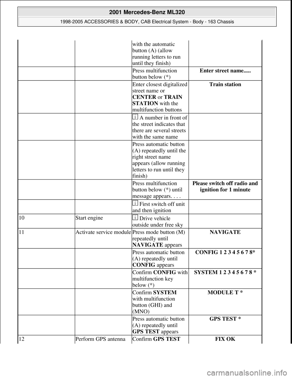
with the automatic
button (A) (allow
running letters to run
until they finish)
Press multifunction
button below (*)Enter street name.....
Enter closest digitalized
street name or
CENTER or TRAIN
STATION with the
multifunction buttonsTrain station
A number in front of
the street indicates that
there are several streets
with the same name
Press automatic button
(A) repeatedly until the
right street name
appears (allow running
letters to run until they
finish)
Press multifunction
button below (*) until
message appears. . . .Please switch off radio and
ignition for 1 minute
First switch off unit
and then ignition
10Start engine Drive vehicle
outside under free sky
11Activate service modulePress mode button (M)
repeatedly until
NAVIGATE appearsNAVIGATE
Press automatic button
(A) repeatedly until
CONFIG appearsCONFIG 1 2 3 4 5 6 7 8*
Confirm CONFIGwith
multifunction key
below (*)SYSTEM 1 2 3 4 5 6 7 8 *
Confirm SYSTEM
with multifunction
button (GHI) and
(MNO)MODULE T *
Press automatic button
(A) repeatedly until
GPS TEST appearsGPS TEST *
12Perform GPS antenna Confirm GPS TEST FIX OK
2001 Mercedes-Benz ML320
1998-2005 ACCESSORIES & BODY, CAB Electrical System - Body - 163 Chassis
me
Saturday, October 02, 2010 3:30:13 PMPage 409 © 2006 Mitchell Repair Information Company, LLC.
Page 2066 of 4133

GF54.30-P-2004A
Control buttons, location/task
24.10.96
MODEL
129, 140 as of 1.6.96,
163, 170
The instrument cluster has two control buttons which are on the left
or right next to the speedometer.
The
right control button
is used to adjust the time (refer to Owner's
Manual).
-----------------------------------------------------------------------------------------
The
left control button
is used
D
to regulate the instrument illumination
D
to activate the display illumination
D
to reset the trip odometer display
D
to operate the maintenance display (model 170 only bis 05.97)
D
to operate the Active Service System ASSYST (as of 06.97)
-----------------------------------------------------------------------------------------
n
Purpose/function of terminal 58d, instrument
display illumination
Engines 112, 113, 611 (engines with oil
sensor)
GF54.30-P-3008A
n
Electronic clock
GF54.30-P-3011A
n
Active Service System (ASSYST)
GF00.20-P-0003-01A
Operating instructions, resetting
Model 210 as of 01.03.97 with engines M111,
OM 602, OM 604, OM 605 and
OM 606
As of 06/97 models 129, 140, 170, 202 except
engines 112, 113, 611
(valid for engines with oil level switch)
GF00.20-P-0003-01B
Copyright DaimlerChrysler AG 05.06.2006 CD-Ausgabe G/10/04 . This WIS print-out will not be recorde
d by Modification services.
Page 1
Page 2228 of 4133
GF54.30-P-3011A
Electronic clock, location/function
24.10.96
MODEL
129, 140 as of 1.6.96,
163, 168, 170,
202 as of 1.8.96,
208 up to 31.7.99,
210 as of 1.6.96 up to 30.6.99
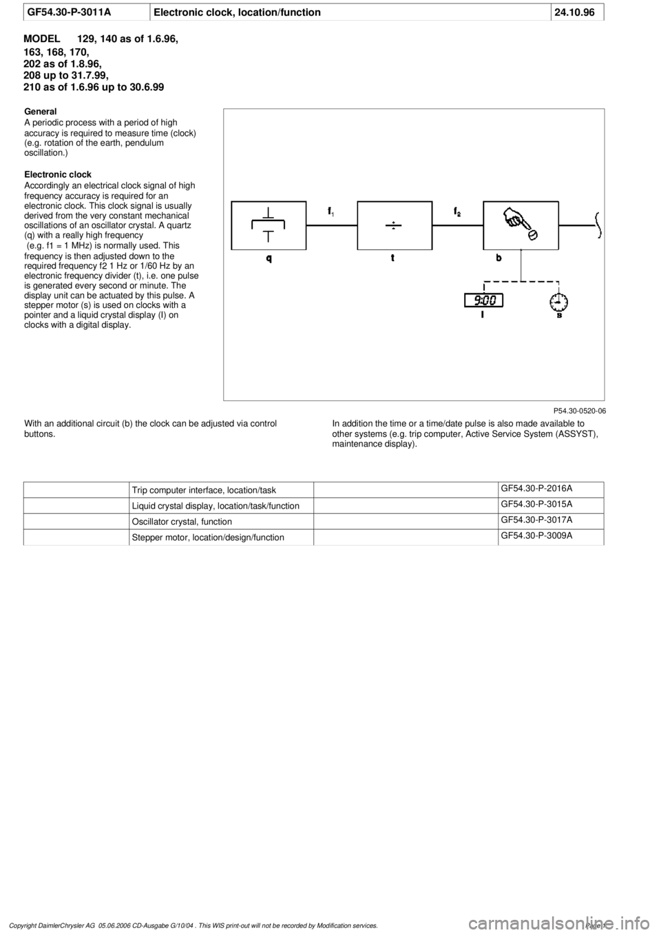
P54.30-0520-06
General
A periodic process with a period of high
accuracy is required to measure time (clock)
(e.g. rotation of the earth, pendulum
oscillation.)
Electronic clock
Accordingly an electrical clock signal of high
frequency accuracy is required for an
electronic clock. This clock signal is usually
derived from the very constant mechanical
oscillations of an oscillator crystal. A quartz
(q) with a really high frequency
(e.g. f
1
= 1 MHz) is normally used. This
frequency is then adjusted down to the
required frequency f
2
1 Hz or 1/60 Hz by an
electronic frequency divider (t), i.e. one pulse
is generated every second or minute. The
display unit can be actuated by this pulse. A
stepper motor (s) is used on clocks with a
pointer and a liquid crystal display (I) on
clocks with a digital display.
With an additional circuit (b) the clock can be adjusted via control
buttons.
In addition the time or a time/date pulse is also made available to
other systems (e.g. trip computer, Active Service System (ASSYST),
maintenance display).
Trip computer interface, location/task
GF54.30-P-2016A
Liquid crystal display, location/task/function
GF54.30-P-3015A
Oscillator crystal, function
GF54.30-P-3017A
Stepper motor, location/design/function
GF54.30-P-3009A
Copyright DaimlerChrysler AG 05.06.2006 CD-Ausgabe G/10/04 . This WIS print-out will not be recorde
d by Modification services.
Page 1
Page 3217 of 4133
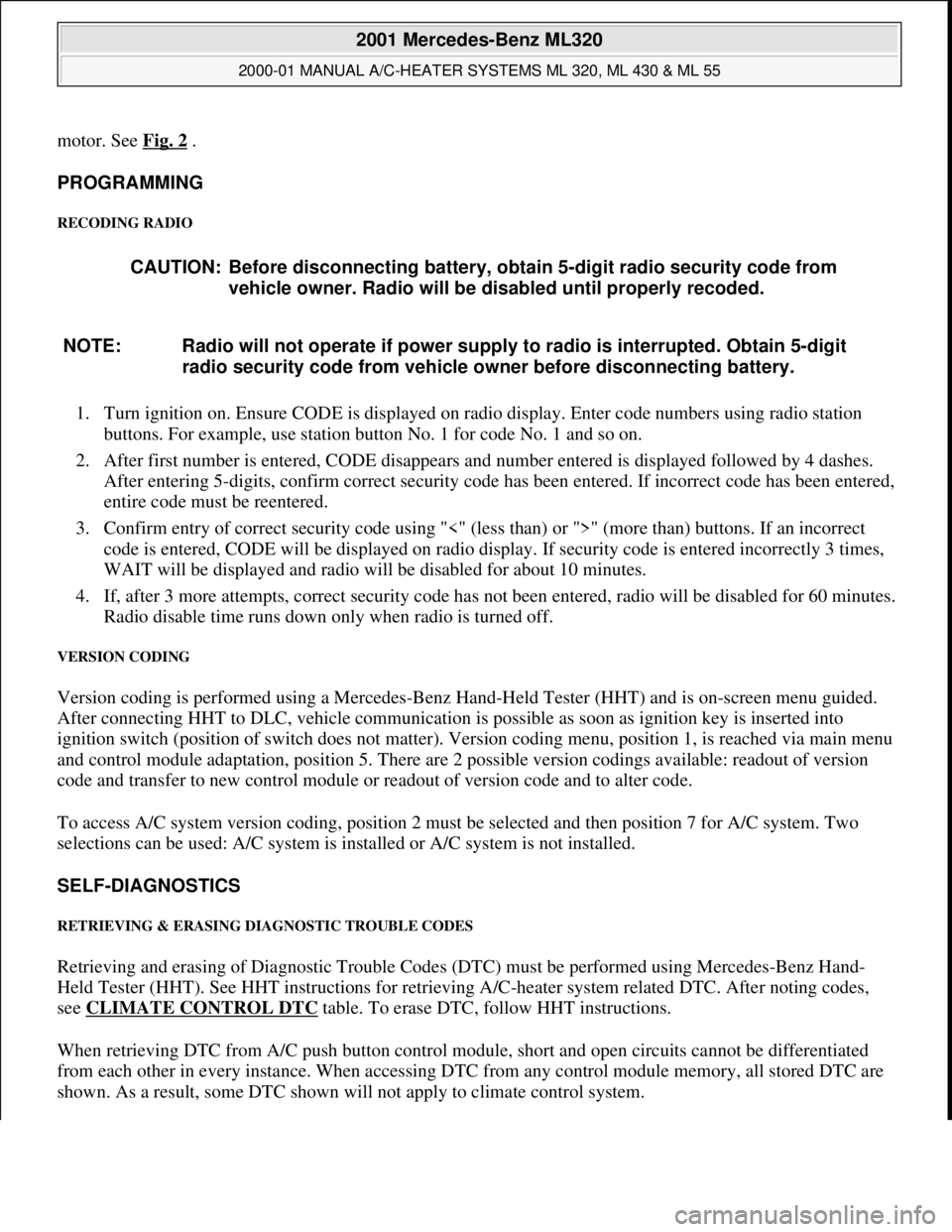
motor. See Fig. 2 .
PROGRAMMING
RECODING RADIO
1. Turn ignition on. Ensure CODE is displayed on radio display. Enter code numbers using radio station
buttons. For example, use station button No. 1 for code No. 1 and so on.
2. After first number is entered, CODE disappears and number entered is displayed followed by 4 dashes.
After entering 5-digits, confirm correct security code has been entered. If incorrect code has been entered,
entire code must be reentered.
3. Confirm entry of correct security code using "<" (less than) or ">" (more than) buttons. If an incorrect
code is entered, CODE will be displayed on radio display. If security code is entered incorrectly 3 times,
WAIT will be displayed and radio will be disabled for about 10 minutes.
4. If, after 3 more attempts, correct security code has not been entered, radio will be disabled for 60 minutes.
Radio disable time runs down only when radio is turned off.
VERSION CODING
Version coding is performed using a Mercedes-Benz Hand-Held Tester (HHT) and is on-screen menu guided.
After connecting HHT to DLC, vehicle communication is possible as soon as ignition key is inserted into
ignition switch (position of switch does not matter). Version coding menu, position 1, is reached via main menu
and control module adaptation, position 5. There are 2 possible version codings available: readout of version
code and transfer to new control module or readout of version code and to alter code.
To access A/C system version coding, position 2 must be selected and then position 7 for A/C system. Two
selections can be used: A/C system is installed or A/C system is not installed.
SELF-DIAGNOSTICS
RETRIEVING & ERASING DIAGNOSTIC TROUBLE CODES
Retrieving and erasing of Diagnostic Trouble Codes (DTC) must be performed using Mercedes-Benz Hand-
Held Tester (HHT). See HHT instructions for retrieving A/C-heater system related DTC. After noting codes,
see CLIMATE CONTROL DTC
table. To erase DTC, follow HHT instructions.
When retrieving DTC from A/C push button control module, short and open circuits cannot be differentiated
from each other in every instance. When accessing DTC from any control module memory, all stored DTC are
shown. As a result, some DTC shown will not appl
y to climate control system. CAUTION: Before disconnecting battery, obtain 5-digit radio security code from
vehicle owner. Radio will be disabled until properly recoded.
NOTE: Radio will not operate if power supply to radio is interrupted. Obtain 5-digit
radio security code from vehicle owner before disconnecting battery.
2001 Mercedes-Benz ML320
2000-01 MANUAL A/C-HEATER SYSTEMS ML 320, ML 430 & ML 55
me
Saturday, October 02, 2010 3:25:10 PMPage 6 © 2006 Mitchell Repair Information Company, LLC.