Page 3280 of 4133

Function
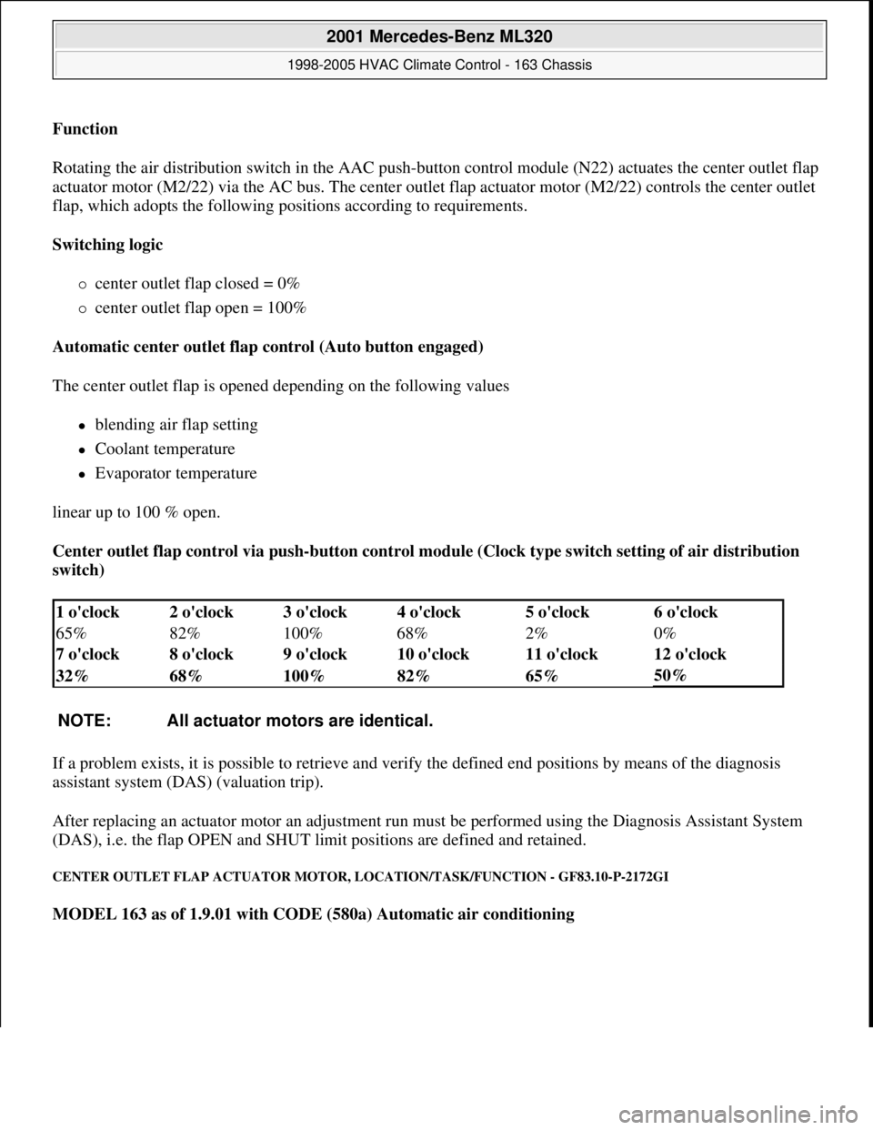
Rotating the air distribution switch in the AAC push-
button control module (N22) actuates the center outlet flap
actuator motor (M2/22) via the AC bus. The center outlet flap actuator motor (M2/22) controls the center outlet
flap, which adopts the following positions according to requirements.
Switching logic
center outlet flap closed = 0%
center outlet flap open = 100%
Automatic center outlet flap control (Auto button engaged)
The center outlet flap is opened depending on the following values
blending air flap setting
Coolant temperature
Evaporator temperature
linear up to 100 % open.
Center outlet flap control via push-button control module (Clock type switch setting of air distribution
switch)
If a problem exists, it is possible to retrieve and verify the defined end positions by means of the diagnosis
assistant system (DAS) (valuation trip).
After replacing an actuator motor an adjustment run must be performed using the Diagnosis Assistant System
(DAS), i.e. the flap OPEN and SHUT limit positions are defined and retained.
CENTER OUTLET FLAP ACTUATOR MOTOR, LOCATION/TASK/FUNCTION - GF83.10-P-2172GI
MODEL 163 as of 1.9.01 with CODE (580a) Automatic air conditioning
1 o'clock 2 o'clock 3 o'clock 4 o'clock 5 o'clock6 o'clock
65% 82% 100% 68% 2%
0%
7 o'clock 8 o'clock 9 o'clock 10 o'clock 11 o'clock
12 o'clock
32% 68% 100% 82% 65%
50%
NOTE: All actuator motors are identical.
2001 Mercedes-Benz ML320
1998-2005 HVAC Climate Control - 163 Chassis
me
Saturday, October 02, 2010 3:23:15 PMPage 36 © 2006 Mitchell Repair Information Company, LLC.
Page 3283 of 4133

Defrost function
Defroster nozzle flap open 100 %.
System switched off
Defroster nozzle flap open 100 % (This limp-home capability ensures that the windshield will not fog up even
when a malfunction has occurred)
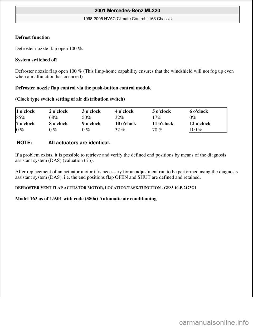
Defroster nozzle flap control via the push-button control module
(Clock type switch setting of air distribution switch)
If a problem exists, it is possible to retrieve and verify the defined end positions by means of the diagnosis
assistant system (DAS) (valuation trip).
After replacement of an actuator motor it is necessary for an adjustment run to be performed using the diagnosis
assistant system (DAS), i.e. the end positions flap OPEN and SHUT are defined and retained.
DEFROSTER VENT FLAP ACTUATOR MOTOR, LOCATION/TASK/FUNCTION - GF83.10-P-2175GI
Model 163 as of 1.9.01 with code (580a) Automatic air conditioning
1 o'clock 2 o'clock 3 o'clock 4 o'clock 5 o'clock6 o'clock
85% 68% 50% 32% 17%
0%
7 o'clock 8 o'clock 9 o'clock 10 o'clock 11 o'clock
12 o'clock
0 % 0 % 0 % 32 % 70 %
100 %
NOTE: All actuators are identical.
2001 Mercedes-Benz ML320
1998-2005 HVAC Climate Control - 163 Chassis
me
Saturday, October 02, 2010 3:23:15 PMPage 39 © 2006 Mitchell Repair Information Company, LLC.
Page 3302 of 4133

clockwise direction to the final indented position (max. cooling), the recirculation switch is bypassed and thus
the fresh air flaps closed, in order to achieve the max. interior cooling (with A/C ON).
TEMPERATURE SELECTOR WHEEL, FUNCTION - GF83.25-P-2102-01GI
Function
The desired in-car temperature is set by turning the temperature selector wheel on the AAC push-button control
module (N22).
The AAC push-button control module (N22) compares the desired temperature with the temperature in the
passenger compartment. The passenger compartment temperature is determined by the in-car temperature
sensor on the AAC push-button control module (N22) and the temperature sensor for the vent air at the center
nozzle, front and rear footwells.
Using the comparison between specified and actual values, the AAC push-button control module (N22)
determines the correct setting of the blending air flaps and actuates these. The selected temperature is reached
and maintained as quickly as possible, if warming or cooling of the interior is necessary.
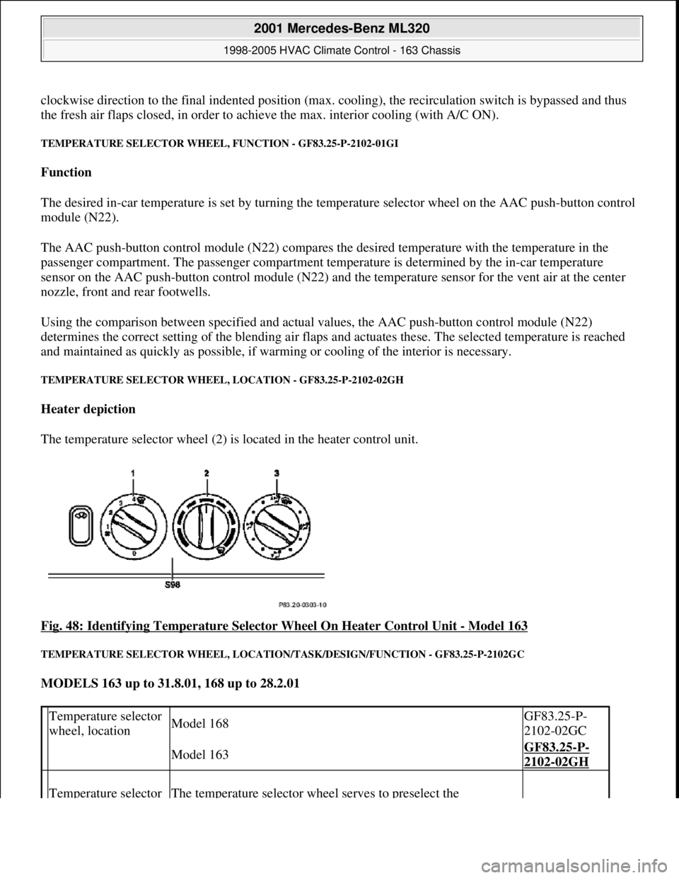
TEMPERATURE SELECTOR WHEEL, LOCATION - GF83.25-P-2102-02GH
Heater depiction
The temperature selector wheel (2) is located in the heater control unit.
Fig. 48: Identifying Temperature Selector Wheel On Heater Control Unit
- Model 163
TEMPERATURE SELECTOR WHEEL, LOCATION/TASK/DESIGN/FUNCTION - GF83.25-P-2102GC
MODELS 163 up to 31.8.01, 168 up to 28.2.01
Temperature selector
wheel, locationModel 168GF83.25-P-
2102-02GC
Model 163GF83.25-P-
2102-02GH
Temperature selector The temperature selector wheel serves to preselect the
2001 Mercedes-Benz ML320
1998-2005 HVAC Climate Control - 163 Chassis
me
Saturday, October 02, 2010 3:23:15 PMPage 58 © 2006 Mitchell Repair Information Company, LLC.
Page 3412 of 4133

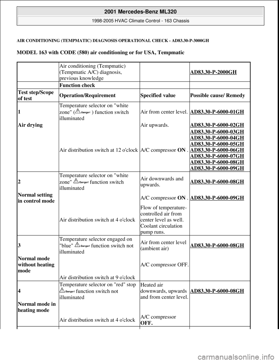
AIR CONDITIONING (TEMPMATIC) DIAGNOSIS OPERATIONAL CHECK - AD83.30-P-3000GH
MODEL 163 with CODE (580) air conditioning or for USA, Tempmatic
Air conditioning (Tempmatic)
(Tempmatic A/C) diagnosis,
previous knowledge
AD83.30-P-2000GH
Function check
Test step/Scope
of test Operation/Requirement Specified value Possible cause/ Remedy
1
Temperature selector on "white
zone" ( ) function switch
illuminated
Air from center level.AD83.30-P-6000-01GH
Air drying Air upwards.AD83.30-P-6000-02GH
Air distribution switch at 12 o'clockA/C compressor ON .
AD83.30-P-6000-03GH
AD83.30
-P-6000-04GH
AD83.30
-P-6000-05GH
AD83.30
-P-6000-06GH
AD83.30
-P-6000-07GH
AD83.30
-P-6000-08GH
AD83.30
-P-6000-09GH
2
Temperature selector on "white
zone" function switch
illuminatedAir downwards and
upwards.AD83.30-P-6000-08GH
Normal setting
in control mode A/C compressor ON .AD83.30-P-6000-09GH
Air distribution switch at 4 o'clock
Flow of temperature-
controlled air from
center level as well.
Coolant circulation
pump runs.
3
Temperature selector engaged on
"blue" function switch not
illuminatedAir from center level
(ambient air)AD83.30-P-6000-08GH
Normal mode
without heating
mode
A/C compressor OFF.
Air distribution switch at 9 o'clock
4
Temperature selector on "red" stop
function switch not
illuminatedHeated air
downwards, upwards
and from center level.
AD83.30-P-6000-08GH
Normal mode in
heating mode
Air distribution switch at 4 o'clockA/C compressor
OFF.
2001 Mercedes-Benz ML320
1998-2005 HVAC Climate Control - 163 Chassis
me
Saturday, October 02, 2010 3:23:17 PMPage 168 © 2006 Mitchell Repair Information Company, LLC.
Page 3900 of 4133

5
Remove key and engage steering lock
6
Unscrew bolt (32c)
Hold the steering wheel (32).
Installation:
Replace bolt (32c).
*BA46.10-P-1001-02A
7
Pull off steering wheel (32)
Pass cables carefully through the openings.
Installation:
Align recesses of the splines
in the steering wheel with the markings on the
steering shaft (arrows).
8
Check fanfare horns and airbag clock spring
contact (A45) for damage
The clock spring contact must not be
turned while the steering wheel is removed
otherwise it will be damaged.
Visual inspection, replace clock spring
contact if necessary:
#
Removing and installing clock spring contact
AR46.10-P-0200GH
9
Install in the reverse order
10
Carry out road test
Tests during the road test:
Turn signal canceling:
When the steering wheel is offset by
more than 1 tooth, satisfactory resetting of the
turn signal is no longer guaranteed.
Airbag indicator lamp:
The SRS indicator lamp must not light up
on full steering lock in both directions.
Steering wheel position:
If the steering wheel is crooked, adjust it
by max. 1 tooth. If the difference is greater:
#
Check toe on front axle and adjust if
necessary, see:
#
Performing chassis alignment check
AR40.20-P-0200A
Steering wheel
Number
Designation
Model 163
BA46.10-P-1001-02A
Bolt, steering wheel to steering shaft
Nm
80
Copyright DaimlerChrysler AG 09.05.2006 CD-Ausgabe G/10/04 . This WIS print-out will not be recorde
d by Modification services.
Page 2
Page:
< prev 1-8 9-16 17-24