1997 MERCEDES-BENZ ML320 clock setting
[x] Cancel search: clock settingPage 2042 of 4133
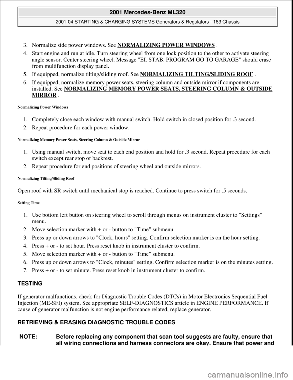
3. Normalize side power windows. See NORMALIZING POWER WINDOWS .
4. Start engine and run at idle. Turn steering wheel from one lock position to the other to activate steering
angle sensor. Center steering wheel. Message "EI. STAB. PROGRAM GO TO GARAGE" should erase
from multifunction display panel.
5. If equipped, normalize tilting/sliding roof. See NORMALIZING TILTING/SLIDING ROOF
.
6. If equipped, normalize memory power seats, steering column and outside mirror if components are
installed. See NORMALIZING MEMORY POWER SEATS, STEERING COLUMN & OUTSIDE
MIRROR .
Normalizing Power Windows
1. Completely close each window with manual switch. Hold switch in closed position for .3 second.
2. Repeat procedure for each power window.
Normalizing Memory Power Seats, Steering Column & Outside Mirror
1. Using manual switch, move seat to each end position and hold for .3 second. Repeat procedure for each
switch except rear stop of backrest.
2. Repeat procedure for end positions of steering wheel and outside mirrors.
Normalizing Tilting/Sliding Roof
Open roof with SR switch until mechanical stop is reached. Continue to press switch for .5 seconds.
Setting Time
1. Use bottom left button on steering wheel to scroll through menus on instrument cluster to "Settings"
menu.
2. Move selection marker with + or - button to "Time" submenu.
3. Press up or down arrows to "Clock, hours" setting. Confirm selection marker is on the hour setting.
4. Press + or - to set hour. Press reset knob in instrument cluster to confirm.
5. Move selection marker with + or - button to "Time" submenu.
6. Press up or down arrows to "Clock, minutes" setting. Confirm selection marker is on the minutes setting.
7. Press + or - to set minute. Press reset knob in instrument cluster to confirm.
TESTING
If generator malfunctions, check for Diagnostic Trouble Codes (DTCs) in Motor Electronics Sequential Fuel
Injection (ME-SFI) system. See appropriate SELF-DIAGNOSTICS article in ENGINE PERFORMANCE. If
cause of generator malfunction is not engine performance related, replace generator.
RETRIEVING & ERASING DIAGNOSTIC TROUBLE CODES
NOTE: Before replacing any component that scan tool suggests are faulty, ensure that
all wiring connections and harness connectors are okay. Ensure that power and
2001 Mercedes-Benz ML320
2001-04 STARTING & CHARGING SYSTEMS Generators & Regulators - 163 Chassis
me
Saturday, October 02, 2010 3:20:32 PMPage 8 © 2006 Mitchell Repair Information Company, LLC.
Page 2066 of 4133

GF54.30-P-2004A
Control buttons, location/task
24.10.96
MODEL
129, 140 as of 1.6.96,
163, 170
The instrument cluster has two control buttons which are on the left
or right next to the speedometer.
The
right control button
is used to adjust the time (refer to Owner's
Manual).
-----------------------------------------------------------------------------------------
The
left control button
is used
D
to regulate the instrument illumination
D
to activate the display illumination
D
to reset the trip odometer display
D
to operate the maintenance display (model 170 only bis 05.97)
D
to operate the Active Service System ASSYST (as of 06.97)
-----------------------------------------------------------------------------------------
n
Purpose/function of terminal 58d, instrument
display illumination
Engines 112, 113, 611 (engines with oil
sensor)
GF54.30-P-3008A
n
Electronic clock
GF54.30-P-3011A
n
Active Service System (ASSYST)
GF00.20-P-0003-01A
Operating instructions, resetting
Model 210 as of 01.03.97 with engines M111,
OM 602, OM 604, OM 605 and
OM 606
As of 06/97 models 129, 140, 170, 202 except
engines 112, 113, 611
(valid for engines with oil level switch)
GF00.20-P-0003-01B
Copyright DaimlerChrysler AG 05.06.2006 CD-Ausgabe G/10/04 . This WIS print-out will not be recorde
d by Modification services.
Page 1
Page 2236 of 4133

GF00.20-P-2009A
Engine oil monitor function
24.10.96
MODEL
129 with ENGINE 112, 113
MODEL
163 with ENGINE 112, 113, 612
MODEL
168 with ENGINE 166, 668
MODEL
202 with ENGINE 112, 611
MODEL
208 up to 31.7.99 with ENGINE 112, 113
MODEL
210 up to 30.6.99 with ENGINE 112, 113, 611
General
The oil level is constantly monitored by the oil sensor, and the
appropriate data transmitted to the processor by the ASSYST.
Oil replenishments are detected automatically and result in a bonus,
which extends the service interval accordingly.
An excess oil level or insufficient oil level appears in the display
together with the oil can symbol.
Display of low oil level at maximum:
D
at driver request
Display of warnings: D
automatically, at the earliest 60 s after engine start and oil
temperature greater than 60°C:
D
if oil level too high: the oil can symbol appears together
with the readout "OIL LEVEL ABOVE MAX". In addition, a
brief warning signal sounds. (On models not fitted with
multifunction displaly, "HI" appears flashing.)
D
if oil level too low: the oil can symbol appears together with
the readout "OIL LEVEL BELOW MIN". In addition, a brief
warning signal sounds. (On models not fitted with multifunction
display, the oil level warning lamp (A1e12) comes on and the
readout "-2L" appears flashing.)
-----------------------------------------------------------------------------------------
D
if oil at minimum: the oil can symbol appears together with
the readout "OIL LEVEL MINIMUM". In addition, a brief
warning signal sounds. (On models not fitted with multifunction
display, the oil level warning lamp (A1e12) comes on.)
D
automatically 13 s after ignition ON:
D
if
no oil
is in engine: the oil can symbol appears together
with the readout "OIL LEVEL BELOW MIN". In addition, a
warning signal sounds. (On models not fitted with multifunction
display, the oil level warning lamp (A1e12) comes on and the
readout "-2L"appears flashing. In addition a brief warning
signal sounds.)
The missing oil quantity displayed no longer changes during the
display. In other words, any change in oil level cannot be observed
directly at the display. The new oil level is only displayed once the
conditions described below exist.
Display of oil quantity at driver request
The text "DISPLAY OIL LEVEL?" appears 10 s after the start switch
has been turned into position "2" (on models not fitted with
multifunction display, the oil can and the clock symbol are displayed).
If the reset button of the trip counter is pressed twice within one sec.
during this readout, for example, "add 1.0L oil" (or "-1.0L")
-----------------------------------------------------------------------------------------
appears in the display if oil level too low. The readout appears only
after the elapse of a waiting time after engine OFF. The waiting time
depends on the engine oil temperature.
It is
D
up to 20°C
30 minutes
D
from 60°C
1 minute
D
The waiting time is between these two limits at other engine oil
temperatures.
Possible readouts are (text in parenthesis relates to models not fitted
with multifunction display.):
D
"OIL LEVEL OKAY" ("o.k."),
D
1.0L, 1.5L, 2L,
D
"Overfilling" ("HI"),
D
"OBSERVE WAITING TIME" (clock symbol flashing and oil can
symbol),
D
"DISPLAY OIL LEVEL" (clock and oil can symbols.)
If there is a fault at the oil sensor (oil level/temperature/quality, B40)
the oil can symbol and the text "OIL LEVEL SENSOR FAULTY"
appears only 30 s after the fault has occurred.
(On models not fitted with multifunction display, the oil level warning
lamp (A1e12) comes on accordingly.)
For diagnosis, read also the injection system control module (N3)
with the HHT. (The instrument cluster (A1) receives the sensor data
through the CAN from the injection system control module (N3)).
-----------------------------------------------------------------------------------------
Oil change
The ASSYST has to be reset each time the oil is changed. Resetting
ASSYST also resets the remaining time and the remaining distance.
Resetting can be performed at the instrument cluster or using the
HHT.
The following data are stored when the system is reset:
D
current kilometer reading rounded off to 100,
D
total oil replenishments in the last interval,
D
remaining distance,
D
remaining time,
D
product of the quality factors,
D
the data of the last 5 resettings in 5 data sets
These data can only be read with the HHT!
If the specified quantity of oil is not replenished when the oil is
changed, the (internal) start distance is reduced.
Detecting oil replenishments
D
With the
HHT
it is possible to retrieve the last 10 oil
replenishments and the corresponding kilometer readings of
the current interval.
D
In the normal case, detection of an oil replenishment is
displayed by the remaining distance in the instrument cluster
being extended
-----------------------------------------------------------------------------------------
Copyright DaimlerChrysler AG 05.06.2006 CD-Ausgabe G/10/04 . This WIS print-out will not be recorde
d by Modification services.
Page 1
Page 2853 of 4133
Warning threshold (in days)
With the HHT it is possible to set a warning threshold of between 5 and 30 days for the remaining time, with a
stepwidth of one day. The basic setting is 30 days.
Display of remaining time
The remaining time is always only displayed in those cases where the following condition is met:
Remaining time (in days) x 40 < remaining distance (in km), and the warning threshold is reached.
The remaining time is displayed in the following cases:
automatically, after 5 s start switch in position 2 or driving, if the warning threshold is reached:
The service symbol and the readout "SERVICE IN ... DAYS" appears for 10 seconds. (On vehicles not
fitted with multifunction display, the current remaining time, the service and the clock symbol appear.)
automatically, after 5 s start switch in position 2 or driving, if the remaining time is exceeded:
The service symbol and the readout "DAYS ... EXCEEDED" appears for 30 s (for 10 s up to mid-July
97). (On vehicles not fitted with multifunction display, the service and the clock symbol appear. The
"remaining time" is displayed with a negative sign (minus sign). The readout flashes in this case.)
After the display reaches the maximum readout of -730 days, the readout remains at this figure! The
readout is displayed with a resolution of 1 day.
As of approx. 06.97 a brief warning signal sounds in addition.
at driver request. The readout is then displayed, as above, for 10 s.
If a speed limit is set at the cruise control, this speed limit is displayed for a short moment before the
ASSYST display.
If certain measured values are not supplied to the ASSYST, e.g. because of failure of a sensor, it switches to
stored substitute values. An appropriate entry is then made in the fault memory of the particular control module.
If the power supply fails, the data are retained. The times without operating voltage (battery disconnected) are
not recorded, however! They can be retroactively included, however, with the HHT.
Active service system
(ASSYST) operating
informationEngine with oil sensor
(e.g. 112, 113, 611)GF00.20-P-0003-01A
Model 210 as of 01.03.97
with engines 111, 602,
604, 605, 606
Model 129, 140, 170, 202 GF00.20-P-0003-01B
2004 Mercedes-Benz ML350
1998-2005 GENINFO Overall vehicle - 163 Chassis
me
Saturday, October 02, 2010 3:47:47 PMPage 208 © 2006 Mitchell Repair Information Company, LLC.
Page 2856 of 4133
Possible readouts are (text in parenthesis relates to models not fitted with multifunction display.):
"OIL LEVEL OKAY" ("o.k."),
1.0L, 1.5L, 2L,
"Overfilling" ("HI"),
"OBSERVE WAITING TIME" (clock symbol flashing and oil can symbol),
"DISPLAY OIL LEVEL" (clock and oil can symbols.)
If there is a fault at the oil sensor (oil level/temperature/quality, B40) the oil can symbol and the text "OIL
LEVEL SENSOR FAULTY" appears only 30 s after the fault has occurred.
(On models not fitted with multifunction display, the oil level warning lamp (A1e12) comes on accordingly.)
For diagnosis, read also the injection system control module (N3) with the HHT. (The instrument cluster (A1)
receives the sensor data through the CAN from the injection system control module (N3)).
Oil change
The ASSYST has to be reset each time the oil is changed. Resetting ASSYST also resets the remaining time and
the remaining distance. Resetting can be performed at the instrument cluster or using the HHT. The following
data are stored when the system is reset:
current kilometer reading rounded off to 100,
total oil replenishments in the last interval,
remaining distance,
remaining time,
product of the quality factors,
the data of the last 5 resettings in 5 data sets
These data can only be read with the HHT!
If the specified quantity of oil is not replenished when the oil is changed, the (internal) start distance is
reduced.
Detecting oil replenishments
With the HHT it is possible to retrieve the last 10 oil replenishments and the corresponding kilometer
readings of the current interval.
In the normal case, detection of an oil replenishment is displayed by the remaining distance in the
instrument cluster being extended
Oil replenishments are always only detected once the following conditions are met:
the replenished quantit
y is at least
2004 Mercedes-Benz ML350
1998-2005 GENINFO Overall vehicle - 163 Chassis
me
Saturday, October 02, 2010 3:47:47 PMPage 211 © 2006 Mitchell Repair Information Company, LLC.
Page 3185 of 4133

AD54.30-P-2000-02GC
Notes on HHT previous knowledge diagnosis
IC
HHT :
The instrument cluster and active service system (ASSYST) sub-
function are checked with HHT, there being the choice of the
following functions for this:
1. Control module version
2. Fault memory
3. Actual values
4. Actuations
5. Control module adaptation
Additional information on test items 2, 3 and 5 can be called up using
the INPUT key
Control module adaptation
The following alternatives are available in the HHT under control
module adaptation:
1.)
Read out coding and transfer to new instrument cluster. IC and
ASSYST.
2.)
Read out/change codings e.g.:
Engine and national variants,
version of fuel tank,
special equipment etc.
3.)
Settings:
1
Clock
2
Put forward kilometer reading
3
Put back kilometer reading
4
Oil change
5
Reset oil change initiated inadvertently
6
Active Service System
7
Enter times with battery disconnected
8
Set minimum oil warning
Before replacing a defective instrument cluster, readout the existing
variant codings (driving data and instrument cluster data) and store in
the HHT on an interim basis. Read in the values stored on an interim
basis again after installing the new instrument cluster.
If it is not possible to read out the stored variant coding, all variant
codings must be input manually (menu-assistance in HHT).
When installing an instrument cluster on an experimental basis, do
not put forward the kilometer reading as it cannot be put back later.
Copyright DaimlerChrysler AG 05.06.2006 CD-Ausgabe G/10/04 . This WIS print-out will not be recorde
d by Modification services.
Page 1
Page 3221 of 4133
TESTS.
Normal Ventilation In Regulating Mode
To check normal ventilation in regulating mode, set temperature selector knob to White range (vertical). Set
mode control knob to 4-o'clock position. Ensure A/C button indicator is illuminated. Air will vent from upper
and lower outlets and A/C compressor will engage. Ambient air will flow from center outlet and coolant
circulation pump will operate. If operation is not as specified, perform the following in order:
Check A/C button activation. See A/C BUTTON under ELECTRICAL TESTS.
Check A/C pressure switch. See A/C REFRIGERANT PRESSURE SWITCH under ELECTRICAL
TESTS.
Economy Setting Not In Heating Mode
To check economy setting without heating mode activated, set temperature selector knob to Blue range. Set
mode control knob to the 9-o'clock position. Ensure A/C button indicator is not illuminated. Ambient air will
flow from center outlet and A/C compressor will NOT be engaged. If operation is not as specified, perform the
following:
Check A/C button activation. See A/C BUTTON under ELECTRICAL TESTS.
Economy Setting In Heating Mode
To check economy setting with heating mode activated, set temperature selector knob to Red range. Set mode
control knob to the 4-o'clock position. Ensure A/C button indicator is not illuminated. Heated air will flow from
lower, upper and center outlets and A/C compressor will NOT be engaged. If operation is not as specified,
perform the following:
Check A/C button activation. See A/C BUTTON under ELECTRICAL TESTS.
Recirculation Mode
To check recirculation mode, press fresh/recirculation button. Ensure fresh/recirculation indicator is
illuminated. Set blower speed knob to position No. 4. Blower fan noise will increase noticeably. If operation is
not as specified, check wiring between recirculated air flap element, heater-A/C switch and No. 16 fuse (15-
amp).
ELECTRICAL TESTS
Voltage Supply Circuit Z50/2
1. Connect socket box to A/C push button control unit and wiring harness. See CONNECTING TEST
EQUIPMENT . Turn ignition on, with engine off. Connect voltmeter positive lead to socket box terminal
No. 7 and negative lead to terminal No. 9.
2. Voltage should be 11-14 volts. If voltage is not as specified, check voltage supply circuit Z50/2 between
No. 16 fuse (15-amp) and connected components. See WIRING DIAGRAMS
. Repair as necessary.
2001 Mercedes-Benz ML320
2000-01 MANUAL A/C-HEATER SYSTEMS ML 320, ML 430 & ML 55
me
Saturday, October 02, 2010 3:25:10 PMPage 10 © 2006 Mitchell Repair Information Company, LLC.
Page 3268 of 4133
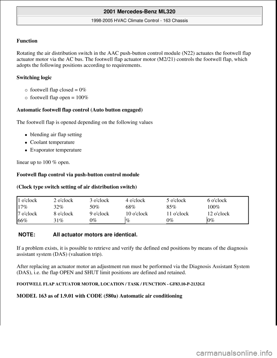
Function
Rotating the air distribution switch in the AAC push-button control module (N22) actuates the footwell flap
actuator motor via the AC bus. The footwell flap actuator motor (M2/21) controls the footwell flap, which
adopts the following positions according to requirements.
Switching logic
footwell flap closed = 0%
footwell flap open = 100%
Automatic footwell flap control (Auto button engaged)
The footwell flap is opened depending on the following values
blending air flap setting
Coolant temperature
Evaporator temperature
linear up to 100 % open.
Footwell flap control via push-button control module
(Clock type switch setting of air distribution switch)
If a problem exists, it is possible to retrieve and verify the defined end positions by means of the diagnosis
assistant system (DAS) (valuation trip).
After replacing an actuator motor an adjustment run must be performed via the Diagnosis Assistant System
(DAS), i.e. the flap OPEN and SHUT limit positions are defined and retained.
FOOTWELL FLAP ACTUATOR MOTOR, LOCATION / TASK / FUNCTION - GF83.10-P-2132GI
MODEL 163 as of 1.9.01 with CODE (580a) Automatic air conditioning
1 o'clock 2 o'clock 3 o'clock 4 o'clock 5 o'clock6 o'clock
17% 32% 50% 68% 85%
100%
7 o'clock 8 o'clock 9 o'clock 10 o'clock 11 o'clock
12 o'clock
66% 31%
0%
%0%0%
NOTE: All actuator motors are identical.
2001 Mercedes-Benz ML320
1998-2005 HVAC Climate Control - 163 Chassis
me
Saturday, October 02, 2010 3:23:15 PMPage 24 © 2006 Mitchell Repair Information Company, LLC.