1997 MERCEDES-BENZ ML320 brake
[x] Cancel search: brakePage 1144 of 4133

340 IndexUseful features 164
Ashtrays and cigarette lighter 168
Cup holder 166
Electrical outlet 170
Garage door opener 180
Interior storage spaces 164
Programming or reprogramming the in-
tegrated remote control 182
Tele Aid* 171
Telephone* 170
Trip computer* 186
V
Vehicle
Locking 28
Locking in an emergency 262
Lowering 276
Proper use of 17
Service battery 278
Towing 283
Unlocking 28
Unlocking in an emergency 261
Vehicle and trailer weights and
ratings 207
Vehicle battery 278Vehicle care
Cup holder 238
Engine cleaning 236
Gear selector lever 238
Hard plastic trim items 238
Headlamps 236
Instrument cluster 238
Leather upholstery 239
Light alloy wheels 238
MB Tex upholstery 239
Ornamental moldings 236
Paintwork 235
Parktronic* system sensor 237
Plastic and rubber parts 239
Power washer 235
Seat belts 238
Steering wheel 238
Tail lamps 236
Tar stains 235
Turn signals 236
Upholstery 239
Vehicle washing 236
Window cleaning 237
Wiper blades 237Vehicle identification number (VIN) 292
Vehicle jack 258
Vehicle lighting
Checking 216
Vehicle tool kit 257
Vehicle with CD-changer* 258
Vehicle washing 236
VIN (Vehicle Identification Number) 292,
315
Voice control system* 315
W
Warning indicators
Parktronic* 155
Warning sounds
Drivers seat belts 64
Parking brake 48
Warranty coverage 291
Washer fluid see Windshield washer fluid
Washing the vehicle 234
Page 1150 of 4133

GF54.30-P-3010A
Function of acoustic warnings
24.10.96
MODEL
129, 140 as of 1.6.96,
163, 168, 170,
202 as of 1.8.96,
208 up to 31.7.99,
210 as of 1.6.96 up to 30.6.99
Display
Function
Turn signal indicator
ticking
Switching on the turn signal indicator is
indicated acoustically by the turn signal
indicator ticking. The driver's attention is
brought to a defect in the turn signal system
by the turn signal indicator ticking at a higher
frequency.
Turn signal indicator ticking is generated
electromagnetically. The frequency
corresponds to that of the turn signal indicator
lamp.
The signal comes from the combination relay
(turn signal indicator with trailer coupling, rear
window defroster), wiper motor, ATA (N10/2),
on model 210 from the multi-function control
module (N10-1) or from the driver-side signal-
acquisition and actuation module (SAM)
(N10/1), on model 163 from the All-Activity
Module (AAM, N10), on model 168 it is
generated by the integrated turn signal
indicator control in the instrument cluster (A1).
Parking brake reminderThe parking brake warning sounds when
terminal 15g is ON from a speed of approx. 5
km/h.
Piezoelectric loudspeaker (quartz), function
GF54.30-P-3017A
Gear warning, model 168
only with automatic
transmission or automatic
clutch
The acoustic gear warning is active, when
D
a gear is engaged
and
D
the brake is
not
depressed
and
D
the accelerator pedal is
not
pressed
and
D
the driver's door is opened.
These conditions are processed in the gear
recognition module (A61) or in the automatic
clutch control module (N15/4). The
information on the status of the driver's door
is available as a CAN message. It is
transmitted by the instrument cluster (A1).
Piezoelectric loudspeaker (quartz), function
GF54.30-P-3017A
Speed warning
The speed warning sounds when terminal
15g is ON from a speed of approx. 120 km/h.
(on national variants only)
Piezoelectric loudspeaker (quartz), function
GF54.30-P-3017A
Speed limit warning
The warning sounds if the set maximum
speed is exceeded by at least 6 km/h.
(on vehicles with variable cruise control only)
Piezoelectric loudspeaker (quartz), function
GF54.30-P-3017A
Seat belt reminder
On national variants only
Piezoelectric loudspeaker (quartz), function
GF54.30-P-3017A
Switched-on lights
reminder
The switched-on lights reminder sounds when
terminal 15g is OFF, terminal 58k is ON,
when the starter key is removed and the
driver's door is opened.
Piezoelectric loudspeaker (quartz), function
GF54.30-P-3017A
Key reminder
The key reminder when terminal 15g is OFF
and the driver's door is open when the starter
key is inserted
Piezoelectric loudspeaker (quartz), function
GF54.30-P-3017A
Soft top reminder, model
170 only
The soft top reminder sounds when terminal
15 is ON and soft top reminder input is on low
level.
Piezoelectric loudspeaker (quartz), function
GF54.30-P-3017A
Copyright DaimlerChrysler AG 05.06.2006 CD-Ausgabe G/10/04 . This WIS print-out will not be recorde
d by Modification services.
Page 1
Page 1172 of 4133
Remove/Install
1 - Remove transmission with torque converter. See REMOVE/INSTALL TRANSMISSION WITH
TORQUE CONVERTER.
2 - Put transmission down on workbench. See Fig. 1
.
3 - Take transmission housing (1) off torque converter housing (2). See Fig. 1
.
4 - Pull torque converter housing (2) off transmission housing (1).
5 - Unscrew internal Torx drive bolts (4a) of oil pump (4).
6 - Screw two opposed bolts (a) into the oil pump housing (4) and press the oil pump (4) out of the
converter housing (2) by applying light blows with a plastic hammer.
Inspect
7 - Check oil pump (4).
8 - Check teflon rings (5a) of multi-disk brake B1 (5), replace if necessary.
9 - Install in the reverse order. NOTE: Internal Torx drive bolts (2a) 15 bolts and internal Torx drive bolts (1a) 2
bolts.
NOTE: The intermediate panel (6) on the torque converter housing (2) can usually
be used several times. The panel must not be coated with sealant.
NOTE: Bolt, transmission housing to converter housing. See Fig. 2
.
NOTE: Ensure that the multi-disk clutch K1 (3) does not fall out.
NOTE: Bolt, oil pump with multi-disk brake B1 to converter housing. See Fig. 2
.
NOTE: According to condition: Dismantle and assemble oil pump. See
DISMANTLING & ASSEMBLING OIL PUMP
.
NOTE: Insert both teflon rings (5a) into groove with grease so that the joint stays
together.
2001 Mercedes-Benz ML320
1998-03 AUTOMATIC TRANSMISSIONS Complete Transmissions - ML 320 - 722.662
me
Saturday, October 02, 2010 3:15:25 PMPage 3 © 2006 Mitchell Repair Information Company, LLC.
Page 1197 of 4133
Fig. 18: Shift From 1 To 2, Function (Second Gear Engaged)
Courtesy of MERCEDES-BENZ OF NORTH AMERICA.
Aim
Engage front multiple-disc clutch (K1), disengage front multiple-disc brake (B1).
Operation
1st Gear Engaged See Fig. 16.
The end face of the 1-2/4-5 command valve (31a) is kept depressurized via the 1-2 and 4-5 shift solenoid valve
(Y3/6y3). Via the 1-2/4-5 holding pressure shift valve (28a), working pressure (p-A) is applied to the front
mutiple-disc clutch (K1) is depressurized.
Shift Phase
See Fig. 17
Via the 1-2 and 4-5 shift solenoid valve (Y3/6y3), the shift valve pressure (p-SV) is directed onto the end face
of the command valve 1-2/4-5 (31a). The 1-2/4-5 command valve (31a) is displaced and the shift pressure (p-S)
coming from the 1-2/4-5 shift pressure shift valve (29a) via the 1-2/4-5 command valve (31a) is directed to the
front multiple-disc clutch (K1). At the same time the front multiple-disc brake (B1) is subjected to overlap
pressure from the 1-2/4-5 overlap regulating valve (30a).
The B1 pressure acting on the end face of the 1-2/4-5 shift pressure shift valve (29a) is superseded by the
working pressure (p-A). The increasing shift pressure (p-S) at the front multiple-disc clutch (K1) acts on the
annular area of the 1-2/4-5 overlap regulating valve (30a). With an appropriate pressure level at the 1-2/4-5
holding pressure shift valve (28a) this valve switches over.
2nd Gear Engaged
See Fig. 18.
After the gear change is complete, the pressure on the end face of the 12-/4-5 command valve (31a) is reduced
via the 1-2 and 4-5 shift solenoid valve (Y3/6y3) and the command value is pushed back into its original
position. Via the 1-2/4-5 holding pressure shift valve (28a) working pressure (p-A) now reaches the front
multiple-disc clutch (K1) via the 1-2/4-5 command valve (31a).
The front multiple-disc brake (B1) is disengaged (depressurized). The spring in the 1-2/4-5 shift pressure shift
valve (29a) pushes this into its original position.
Continuation
Operating Pressure, Function
See OPERATING PRESSURE, FUNCTION
.
Shift Pressure, Function
2001 Mercedes-Benz ML320
1998-03 AUTOMATIC TRANSMISSIONS Complete Transmissions - ML 320 - 722.662
me
Saturday, October 02, 2010 3:15:25 PMPage 28 © 2006 Mitchell Repair Information Company, LLC.
Page 1202 of 4133
The parking lock gear and drive flange are connected to the output shaft by gearing.
Freewheels F1 and F2 optimize shifting. The front freewheel (F1) rests against the stator shaft extension on the
transmission side and connects the sun gear of the front planetary gear set tot the transmission housing in the
locking direction.
The torque converter housing and transmission housing are made of a metal alloy. They are bolted together and
centered via the outer multiple-disc carrier of the multiple-disc brake B1. A coated intermediate panel seals the
two components.
The oil pump and outer multiple-disc carrier of the front multiple-disc brake are bolted to the converter housing.
The mechanical part consists of the propeller shaft, output shaft, a sun gear shaft and three planetary gearsets
which are coupled together.
In transmissions for powerful engines, the planetary gearsets have 4 planetary gears, while for less powerful
engines the front and rear planetary gear system has three planetary gear wheels. The stator shaft is pressed into
this and is secured against turning by a spline.
The rear freewheel (F2) connects the sun gear of the center planetary gear set to the sun gear of the rear
planetary gearset in the locking direction.
The electrohydraulic control unit consists of the shift plate made of light alloy for hydraulic control and an
electronic control unit.
The electrical control unit consists of a supporting body made of plastic in which the electrical components are
combined. The shell is screwed tot he shift plate. Conductor tracks which are integrated into the shell, connect
the electric components to a plug connector. This 13-pin plug connector forms the connection with the vehicle-
side wiring harness and with the ETC 5 (Electronic Transmission Control) control module (N15/5) via a
bayonet lock.
Automatic Transmission, Location Of Mechanical Parts
See AUTOMATIC TRANSMISSION, LOCATION OF MECHANICAL PARTS
.
Automatic Transmission, Location Of Electric/Electronic Components
See AUTOMATIC TRANSMISSION, LOCATION OF ELECTRIC/ELECTRONIC
COMPONENTS.
Automatic Transmission, Location Of Hydraulic Components
See AUTOMATIC TRANSMISSION, POSITION OF HYDRAULIC COMPONENTS
.
Automatic Transmission, Location Of Components, Floor Shift
See AUTOMATIC TRANSMISSION, LOCATION OF COMPONENTS, FLOOR SHIFT
.
2001 Mercedes-Benz ML320
1998-03 AUTOMATIC TRANSMISSIONS Complete Transmissions - ML 320 - 722.662
me
Saturday, October 02, 2010 3:15:26 PMPage 33 © 2006 Mitchell Repair Information Company, LLC.
Page 1205 of 4133
If the parking lock is engaged, the ignition key has been removed and the service brake is not activated, the
locking pawl (39) blocks the detent plate (38). See Fig. 19
. The park pawl cannot be released. The park pawl
can only be released by turning the ignition key to position "1" and pressing the brake pedal. Starting from
ignition key position "1" the locking cam (61) in the steering lock releases the control cable (53). When the
brake pedal is depressed, the lock lever (55) and roller (58) are twisted down, the return spring at the brake
pedal (57) is tensionsed and the release lever (56) is released.
The force of the pressure spring (64) is now applied via the cables (53, 54) against the lesser force of the
pressure spring (62) and pulls the locking valve (60) in front of the contour of the locking cam (61). The locking
pawl (39) is simultaneously turned via the link rod and lifts up off the detent plate (38).
The parking lock can now be released.
The design of the parking lock interlock is the same as for the steering lock interlock and it functions with
reciprocal action to the steering lock interlock.
Steering Lock Interlock, Function
2001 Mercedes-Benz ML320
1998-03 AUTOMATIC TRANSMISSIONS Complete Transmissions - ML 320 - 722.662
me
Saturday, October 02, 2010 3:15:26 PMPage 36 © 2006 Mitchell Repair Information Company, LLC.
Page 1207 of 4133
Operation
The steering lock interlock prevents the ignition key being removed when the parking lock is not engaged.
The locking pawl (39) is positioned on the exterior contour of the detent plate (38) if the parking lock is not
engaged and if the brake pedal is not depressed. See Fig. 20
.
The cables (53, 54) hold the locking valve (60) in its position in front of the locking cam (61) against the force
of the pressure spring. Therefore, the ignition key cannot be turned to the "0" position.
In selector lever position "P" and with the brake pedal in the rest position, the force of the return spring (57) can
pull the locking pawl (39) under the stop at the detent plate (38) and the pressure spring (62) simultaneously
pulls the locking valve (60) away from the locking cam (61).
The ignition key can now be turned to the "0" position and removed from the ignition.
The design of the parking lock interlock is the same as for the steering lock interlock and it functions with
reciprocal action to the steering lock interlock.
Parking Lock, Location/Task/Design/Function
See PARKING LOCK, LOCATION/TASK/DESIGN/FUNCTION
.
Parking Lock, Location/Task/Design/Function
2001 Mercedes-Benz ML320
1998-03 AUTOMATIC TRANSMISSIONS Complete Transmissions - ML 320 - 722.662
me
Saturday, October 02, 2010 3:15:26 PMPage 38 © 2006 Mitchell Repair Information Company, LLC.
Page 1208 of 4133
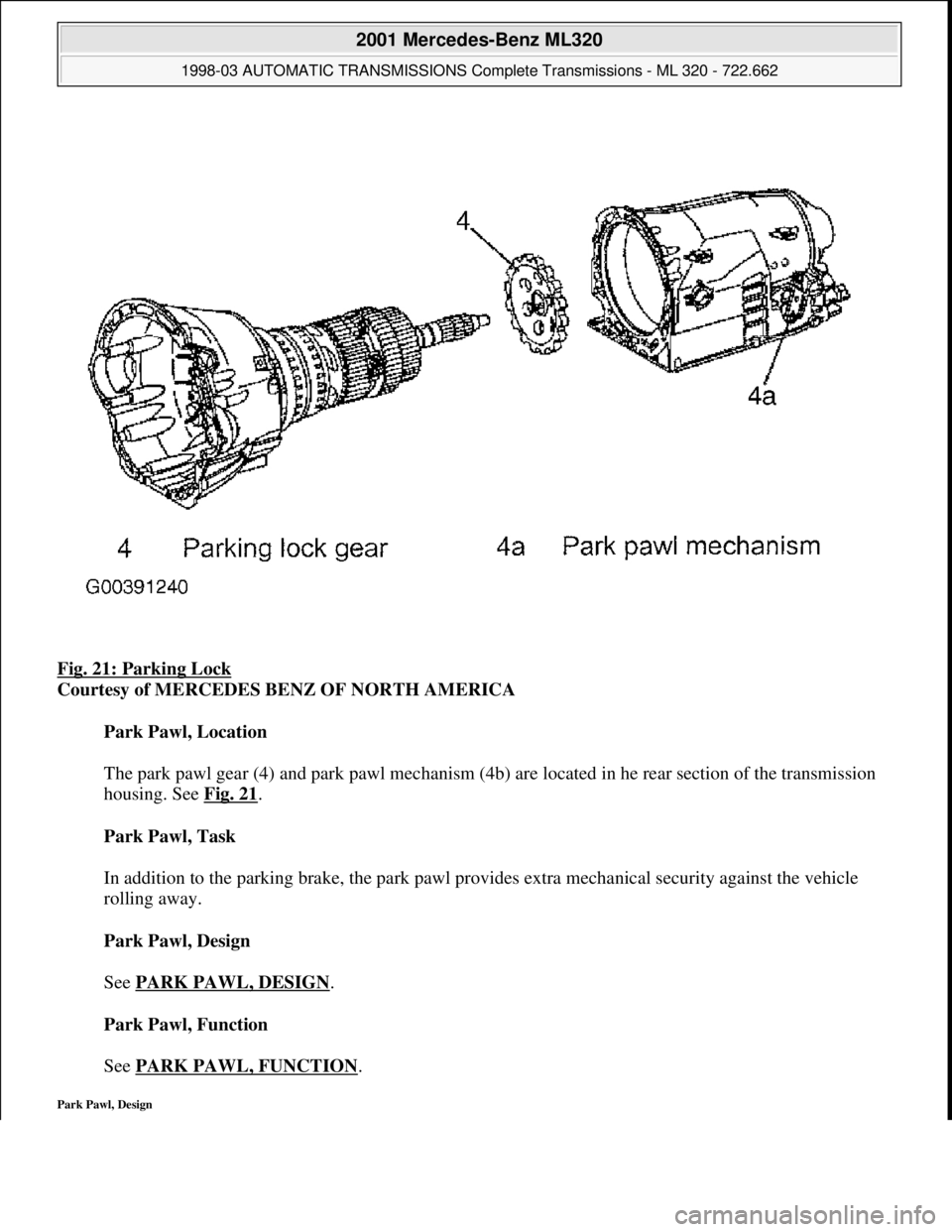
Fig. 21: Parking Lock
Courtesy of MERCEDES BENZ OF NORTH AMERICA
Park Pawl, Location
The park pawl gear (4) and park pawl mechanism (4b) are located in he rear section of the transmission
housing. See Fig. 21
.
Park Pawl, Task
In addition to the parking brake, the park pawl provides extra mechanical security against the vehicle
rolling away.
Park Pawl, Design
See PARK PAWL, DESIGN
.
Park Pawl, Function
See PARK PAWL, FUNCTION
.
Park Pawl, Design
2001 Mercedes-Benz ML320
1998-03 AUTOMATIC TRANSMISSIONS Complete Transmissions - ML 320 - 722.662
me
Saturday, October 02, 2010 3:15:26 PMPage 39 © 2006 Mitchell Repair Information Company, LLC.