Page 1706 of 4133
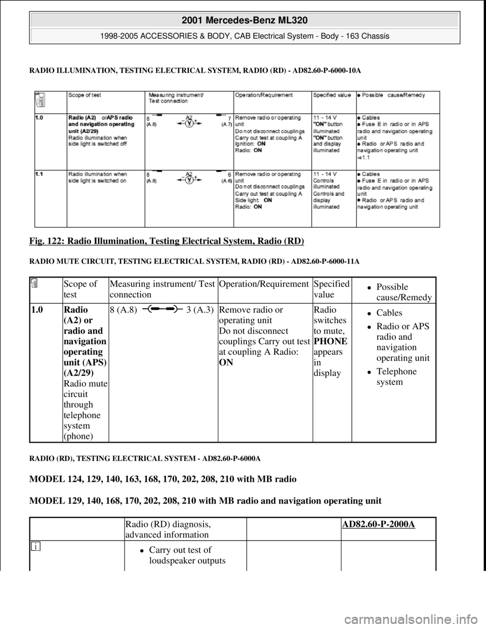
RADIO ILLUMINATION, TESTING ELECTRICAL SYSTEM, RADIO (RD) - AD82.60-P-6000-10A
Fig. 122: Radio Illumination, Testing Electrical System, Radio (RD)
RADIO MUTE CIRCUIT, TESTING ELECTRICAL SYSTEM, RADIO (RD) - AD82.60-P-6000-11A
RADIO (RD), TESTING ELECTRICAL SYSTEM - AD82.60-P-6000A
MODEL 124, 129, 140, 163, 168, 170, 202, 208, 210 with MB radio
MODEL 129, 140, 168, 170, 202, 208, 210 with MB radio and navigation operating unit
Scope of
testMeasuring instrument/ Test
connectionOperation/RequirementSpecified
valuePossible
cause/Remedy
1.0 Radio
(A2) or
radio and
navi
gation
operating
unit (APS)
(A2/29)
Radio mute
circuit
through
telephone
system
(phone)
8 (A.8) 3 (A.3)Remove radio or
operating unit
Do not disconnect
couplings Carry out test
at coupling A Radio:
ON Radio
switches
to mute,
PHONE
appears
in
displayCables
Radio or APS
radio and
navigation
operating unit
Telephone
system
Radio (RD) diagnosis,
advanced information AD82.60-P-2000A
Carry out test of
loudspeaker outputs
2001 Mercedes-Benz ML320
1998-2005 ACCESSORIES & BODY, CAB Electrical System - Body - 163 Chassis
me
Saturday, October 02, 2010 3:30:07 PMPage 211 © 2006 Mitchell Repair Information Company, LLC.
Page 1709 of 4133
Fig. 124: Identifying Adapter Cable (140 589 22 63 00)
Commercially available tools
RADIO AND NAVIGATION UNIT CONNECTOR ASSIGNMENTS - AD82.61-P-2001-02A
Connectors on radio and navigation unit (A2/56)
NumberDesignation
WH58.30-Z-1001-09AMultimeter
Designation
MB radio removal tool
(000 833 03 61)
2001 Mercedes-Benz ML320
1998-2005 ACCESSORIES & BODY, CAB Electrical System - Body - 163 Chassis
me
Saturday, October 02, 2010 3:30:07 PMPage 214 © 2006 Mitchell Repair Information Company, LLC.
Page 1710 of 4133
Fig. 125: Identifying Radio And Navigation Unit Connector Assignments
VERSION CODING FOR RADIO AND NAVIGATION UNIT - AD82.61-P-2001-03A
The table below shows the possible navigation system adaptations to the vehicle. The settings can be changed
with the aid of the handheld tester ("HHT").
Navigation parametersPossible settings
ABS pulse count (pulse count
from wheel speed sensor per
wheel rotation)Factory setting:48 (passenger cars)
Tire sizee.g.:195/50/15
Tire condition Guideline values:
Coding is required only when
tires are changed. Tire wear
occurring while driving is
recognized automatically by the
navigation system.New:Tread depth greater than 5 mm
2001 Mercedes-Benz ML320
1998-2005 ACCESSORIES & BODY, CAB Electrical System - Body - 163 Chassis
me
Saturday, October 02, 2010 3:30:08 PMPage 215 © 2006 Mitchell Repair Information Company, LLC.
Page 1711 of 4133
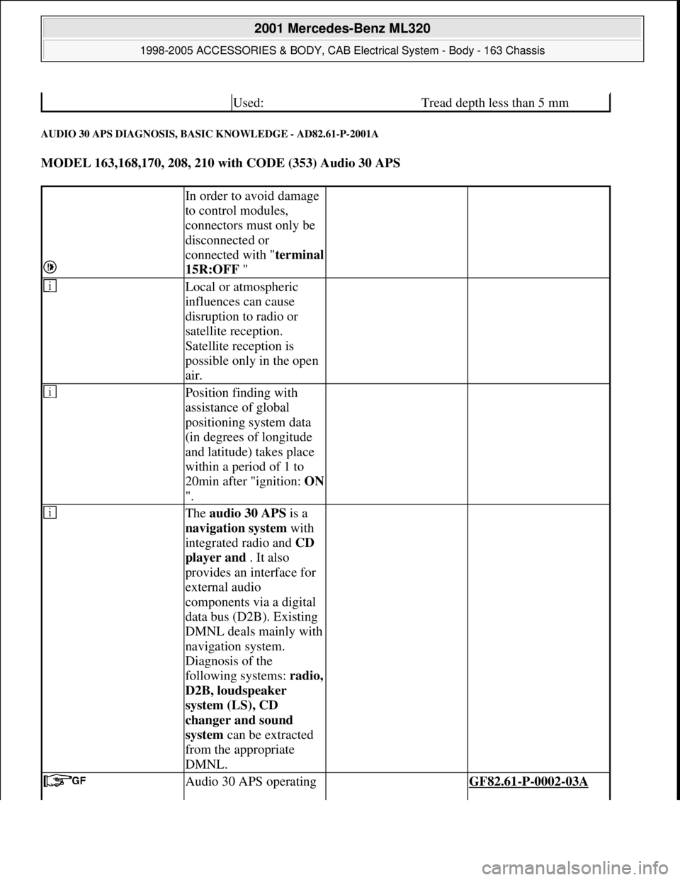
AUDIO 30 APS DIAGNOSIS, BASIC KNOWLEDGE - AD82.61-P-2001A
MODEL 163,168,170, 208, 210 with CODE (353) Audio 30 APS
Used:Tread depth less than 5 mm
In order to avoid damage
to control modules,
connectors must only be
disconnected or
connected with "terminal
15R:OFF "
Local or atmospheric
influences can cause
disruption to radio or
satellite reception.
Satellite reception is
possible only in the open
air.
Position finding with
assistance of global
positioning system data
(in degrees of longitude
and latitude) takes place
within a period of 1 to
20min after "ignition: ON
".
The audio 30 APS is a
navigation system with
integrated radio and CD
player and . It also
provides an interface for
external audio
components via a digital
data bus (D2B). Existing
DMNL deals mainly with
navigation system.
Diagnosis of the
following systems: radio,
D2B, loudspeaker
system (LS), CD
changer and sound
system can be extracted
from the appropriate
DMNL.
Audio 30 APS operating GF82.61-P-0002-03A
2001 Mercedes-Benz ML320
1998-2005 ACCESSORIES & BODY, CAB Electrical System - Body - 163 Chassis
me
Saturday, October 02, 2010 3:30:08 PMPage 216 © 2006 Mitchell Repair Information Company, LLC.
Page 1712 of 4133
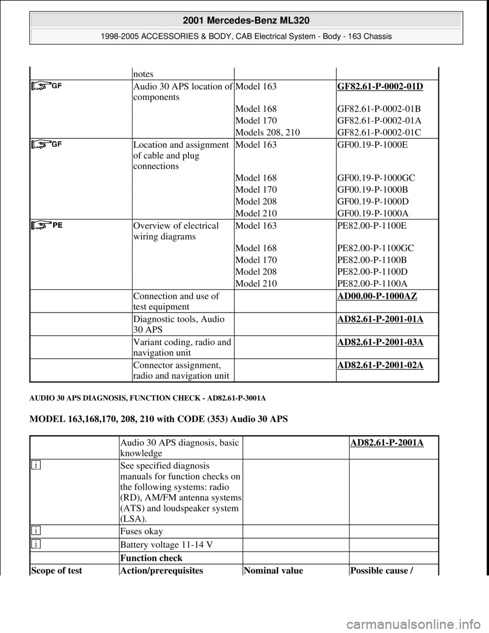
AUDIO 30 APS DIAGNOSIS, FUNCTION CHECK - AD82.61-P-3001A
MODEL 163,168,170, 208, 210 with CODE (353) Audio 30 APS
notes
Audio 30 APS location of
componentsModel 163GF82.61-P-0002-01D
Model 168GF82.61-P-0002-01B
Model 170GF82.61-P-0002-01A
Models 208, 210GF82.61-P-0002-01C
Location and assignment
of cable and plug
connectionsModel 163GF00.19-P-1000E
Model 168GF00.19-P-1000GC
Model 170GF00.19-P-1000B
Model 208GF00.19-P-1000D
Model 210GF00.19-P-1000A
Overview of electrical
wiring diagramsModel 163PE82.00-P-1100E
Model 168PE82.00-P-1100GC
Model 170PE82.00-P-1100B
Model 208PE82.00-P-1100D
Model 210PE82.00-P-1100A
Connection and use of
test equipment AD00.00-P-1000AZ
Diagnostic tools, Audio
30 APS AD82.61-P-2001-01A
Variant coding, radio and
navigation unit AD82.61-P-2001-03A
Connector assignment,
radio and navigation unit AD82.61-P-2001-02A
Audio 30 APS diagnosis, basic
knowledge AD82.61-P-2001A
See specified diagnosis
manuals for function checks on
the following systems: radio
(RD), AM/FM antenna systems
(ATS) and loudspeaker system
(LSA).
Fuses okay
Battery voltage 11-14 V
Function check
Scope of test Action/prerequisites Nominal value Possible cause /
2001 Mercedes-Benz ML320
1998-2005 ACCESSORIES & BODY, CAB Electrical System - Body - 163 Chassis
me
Saturday, October 02, 2010 3:30:08 PMPage 217 © 2006 Mitchell Repair Information Company, LLC.
Page 1713 of 4133
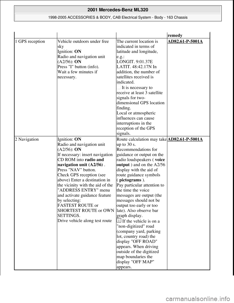
remedy
1 GPS receptionVehicle outdoors under free
sky
Ignition: ON
Radio and navigation unit
(A2/56): ON
Press "I" button (info).
Wait a few minutes if
necessary.The current location is
indicated in terms of
latitude and longitude,
e.g.:
LONGIT. 9:01.37E
LATIT. 48:42.17N In
addition, the number of
satellites received is
indicated.
It is necessary to
receive at least 3 satellite
signals for two-
dimensional GPS location
finding.
Local or atmospheric
influences can cause
interruptions in the
reception of the GPS
signals.AD82.61-P-5001A
2 NavigationIgnition: ON
Radio and navigation unit
(A2/56): ON
If necessary: insert navigation
CD ROM into radio and
navigation unit (A2/56) .
Press "NAV" button.
Check GPS reception (see
above) Enter a destination in
the vicinity with the aid of the
"ADDRESS ENTRY" menu
and activate guidance feature
by selecting:
FASTEST ROUTE or
SHORTEST ROUTE or OWN
SETTINGS.
Drive vehicle along test routeRoute calculation may take
up to 30 s.
Recommendations for
guidance or output on the
radio loudspeakers ( voice
output ) and on the A2/56
display with the aid of
route guidance symbols
( pictograms ).
Pay particular attention to
the time the voice
messages are output (the
messages should not be
output too early or too
late). Also observe bar
graph display.
If the vehicle is on a
"non-digitized" road
(company yard, parking
lot, country road) the
display "OFF ROAD"
appears. When driving
outside of the digitized
map boundaries the
display "OFF MAP"
appears.AD82.61-P-5001A
2001 Mercedes-Benz ML320
1998-2005 ACCESSORIES & BODY, CAB Electrical System - Body - 163 Chassis
me
Saturday, October 02, 2010 3:30:08 PMPage 218 © 2006 Mitchell Repair Information Company, LLC.
Page 1714 of 4133
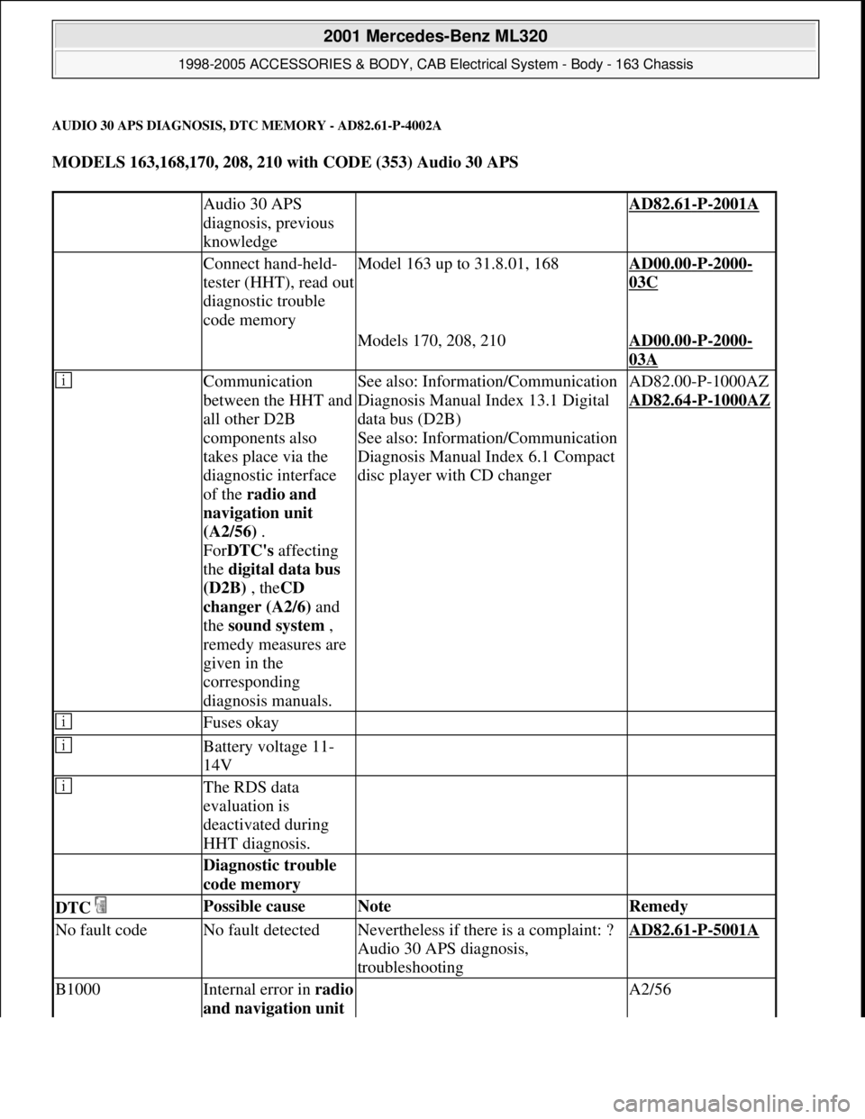
AUDIO 30 APS DIAGNOSIS, DTC MEMORY - AD82.61-P-4002A
MODELS 163,168,170, 208, 210 with CODE (353) Audio 30 APS
Audio 30 APS
diagnosis, previous
knowledge AD82.61-P-2001A
Connect hand-held-
tester (HHT), read out
diagnostic trouble
code memoryModel 163 up to 31.8.01, 168AD00.00-P-2000-
03C
Models 170, 208, 210AD00.00-P-2000-
03A
Communication
between the HHT and
all other D2B
components also
takes place via the
diagnostic interface
of the radio and
navigation unit
(A2/56) .
ForDTC's affecting
the digital data bus
(D2B) , theCD
changer (A2/6) and
the sound system ,
remedy measures are
given in the
corresponding
diagnosis manuals.
See also: Information/Communication
Diagnosis Manual Index 13.1 Digital
data bus (D2B)
See also: Information/Communication
Diagnosis Manual Index 6.1 Compact
disc player with CD changerAD82.00-P-1000AZ
AD82.64
-P-1000AZ
Fuses okay
Battery voltage 11-
14V
The RDS data
evaluation is
deactivated during
HHT diagnosis.
Diagnostic trouble
code memory
DTC Possible cause Note Remedy
No fault codeNo fault detectedNevertheless if there is a complaint: ?
Audio 30 APS diagnosis,
troubleshootingAD82.61-P-5001A
B1000Internal error in radio
and navigation unit A2/56
2001 Mercedes-Benz ML320
1998-2005 ACCESSORIES & BODY, CAB Electrical System - Body - 163 Chassis
me
Saturday, October 02, 2010 3:30:08 PMPage 219 © 2006 Mitchell Repair Information Company, LLC.
Page 1715 of 4133
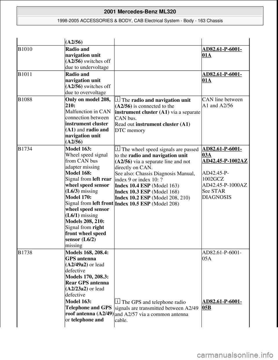
(A2/56)
B1010Radio and
navigation unit
(A2/56) switches off
due to undervoltage AD82.61-P-6001-
01A
B1011Radio and
navigation unit
(A2/56) switches off
due to overvoltage AD82.61-P-6001-
01A
B1088Only on model 208,
210:
Malfunction in CAN
connection between
instrument cluster
(A1) and radio and
navigation unit
(A2/56) The radio and navigation unit
(A2/56) is connected to the
instrument cluster (A1)via a separate
CAN bus.
Read out instrument cluster (A1)
DTC memoryCAN line between
A1 and A2/56
B1734Model 163:
Wheel speed signal
from CAN bus
adapter missing
Model 168:
Signal from left rear
wheel speed sensor
(L6/3) missing
Model 170:
Signal from left front
wheel speed sensor
(L6/1) missing
Models 208, 210:
Signal from right
front wheel speed
sensor (L6/2)
missing The wheel speed signals are passed
to the radio and navigation unit
(A2/56) via a separate line and not
directly on CAN.
See also: Chassis Diagnosis Manual,
index 9 or index 10: ?
Index 10.4 ESP (Model 163)
Index 10.3 ESP (Model 168)
Index 10.2 ESP (Model 208, 210)
Index 10.5 ESP (Model 208)AD82.61-P-6001-
03A
AD42.45
-P-1002AZ
AD42.45-P-
1002GCZ
AD42.45-P-1000AZ
See STAR
DIAGNOSIS
B1738Models 168, 208.4:
GPS antenna
(A2/49a2) or lead
defective
Models 170, 208.3:
Rear GPS antenna
(A2/23a2) or lead
defective AD82.61-P-6001-
05A
Model 163:
Telephone and GPS
roof antenna (A2/49)
or telephone and The GPS and telephone radio
signals are transmitted between A2/49
and A2/57 via a common antenna
cable.AD82.61-P-6001-
05B
2001 Mercedes-Benz ML320
1998-2005 ACCESSORIES & BODY, CAB Electrical System - Body - 163 Chassis
me
Saturday, October 02, 2010 3:30:08 PMPage 220 © 2006 Mitchell Repair Information Company, LLC.