Page 1905 of 4133
RETROFITTING TRAFFICSTAR NAVIGATION SYSTEM - AZ82.61-P-0001I
MODEL 163 up to 30.6.99 except CODE (819) 6-disk CD changer in trunk
System illustration
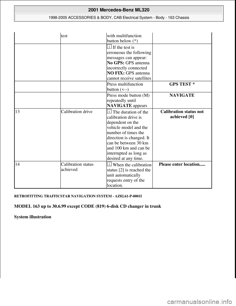
testwith multifunction
button below (*)
If the test is
erroneous the following
messages can appear:
No GPS: GPS antenna
incorrectly connected
NO FIX: GPS antenna
cannot receive satellites
Press multifunction
button (<--)GPS TEST *
Press mode button (M)
repeatedly until
NAVIGATE appearsNAVIGATE
13Calibration drive The duration of the
calibration drive is
dependent on the
vehicle model and the
number of times the
direction is changed. It
can be between 30 km
and 100 km and can be
interrupted as long as
desired at any time.Calibration status not
achieved [0]
14Calibration status
achievedWhen the calibration
status [2] is reached the
unit automatically
requests entry of the
location.Please enter location.....
2001 Mercedes-Benz ML320
1998-2005 ACCESSORIES & BODY, CAB Electrical System - Body - 163 Chassis
me
Saturday, October 02, 2010 3:30:13 PMPage 410 © 2006 Mitchell Repair Information Company, LLC.
Page 1906 of 4133
Fig. 336: Identifying Trafficstar Navigation System Components
Notes on TrafficStar
navigation systemModels 129, 140, 163,
168, 170, 202, 208, 210AH82.61-P-0001-03A
Removal
1Disconnect ground lead
from battery
AR54.10-P-0003A
2Remove radio
AR82.60-P-7502EA
3Remove center console
AR68.20-P-2000GH
4Remove cover below
right instrument panel
AR68.10-P-1520GH
5Remove paneling from
A-pillar Only in area of
instrument panel
AR68.30-P-4050GH
Installation
6Retrofit TrafficStar GPS
antenna on instrument
panel AZ82.61-P-0001-01F
7Connect TrafficStar radio Only on vehicles with AZ82.61-P-0001-02G
2001 Mercedes-Benz ML320
1998-2005 ACCESSORIES & BODY, CAB Electrical System - Body - 163 Chassis
me
Saturday, October 02, 2010 3:30:13 PMPage 411 © 2006 Mitchell Repair Information Company, LLC.
Page 1907 of 4133
Parts ordering notes
RETROFITTING TRAFFIC PRO WIRING HARNESS - AZ82.61-P-0002-01H
Model 163 with transmission 722 up to 30.6.2000
1. Prepare adapter wiring harness (4) as shown in figure.
2. Cut off orange (or) lead for reverse lamp signal (2) at connector (C) and provide with contact spring.
Connector (C) no lon
ger required after cutting off.
and navigation systemsound system
Only on vehicles
without sound systemAZ82.61-P-0001-02I
8Reassemble vehicle, 5-1
9Carrying out start-up and
function check AZ82.61-P-0001-04A
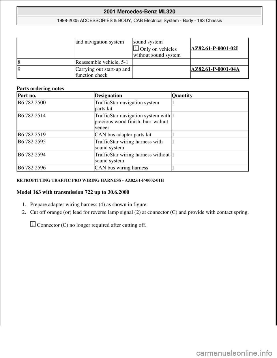
Part no.DesignationQuantity
B6 782 2500TrafficStar navigation system
parts kit1
B6 782 2514TrafficStar navigation system with
precious wood finish, burr walnut
veneer1
B6 782 2519CAN bus adapter parts kit1
B6 782 2595TrafficStar wiring harness with
sound system1
B6 782 2594TrafficStar wiring harness without
sound system1
B6 782 2596CAN bus wiring harness1
2001 Mercedes-Benz ML320
1998-2005 ACCESSORIES & BODY, CAB Electrical System - Body - 163 Chassis
me
Saturday, October 02, 2010 3:30:13 PMPage 412 © 2006 Mitchell Repair Information Company, LLC.
Page 1909 of 4133
Fig. 339: Identifying Telephone/GPS Antenna Splitter And CAN Bus Adapter
5. Connect adapter wiring harness (4) to radio counter connector (7) on standard wiring harness and Traffic
Pro navigation system (1).
Fig. 340: Identifying Adapter Wiring Harness And Radio Counter Connector
6. Connect antenna extension lead (41) to Traffic Pro navi
gation system as shown in figure.
2001 Mercedes-Benz ML320
1998-2005 ACCESSORIES & BODY, CAB Electrical System - Body - 163 Chassis
me
Saturday, October 02, 2010 3:30:13 PMPage 414 © 2006 Mitchell Repair Information Company, LLC.
Page 1912 of 4133
RETROFITTING TRAFFIC PRO NAVIGATION SYSTEM - AZ82.61-P-0002H
MODEL 163 up to 30.6.00
except CODE (810) Sound system
except CODE (819) 6-disk CD changer
except CODE (316) MB GSM cellular telephone (D2B)
except CODE (317) GSM portable cellular telephone (D2B)
System illustration with telephone and GPS roof antenna
Fig. 347: Identifying Traffic Pro Navigation System Components
See notes on radio
connector pin assignmentModels 163.AH82.61-P-0001-05A
Notes on Traffic Pro
navigation systemModels 129, 140, 163,
168, 170, 202, 208, 210.AH82.61-P-0002-01A
Removal
1Disconnect ground cable
of battery
AR54.10-P-0003A
2Remove radio
2001 Mercedes-Benz ML320
1998-2005 ACCESSORIES & BODY, CAB Electrical System - Body - 163 Chassis
me
Saturday, October 02, 2010 3:30:13 PMPage 417 © 2006 Mitchell Repair Information Company, LLC.
Page 1913 of 4133
Parts ordering notes
RETROFITTING CD CHANGER - AZ82.64-P-0001MA
MODEL 163 as of 1.7.99
in combination with Audio 10, Audio 30 radio or COMAND operating and display system and D2B fiber
optical cable
AR82.60-P-7502EA
3Remove center console
AR68.20-P-2000GH
Install
4Retrofit global
positioning system (GPS)
antenna on roof for vehicles with
engine 111 or to 9.99AN82.61-P-7474-04AZ
5Retrofit Traffic Pro
wiring harnessVehicles with automatic
transmission.AZ82.61-P-0002-01H
Vehicles with manual
transmission.AZ82.61-P-0002-01HH
6Fit remaining parts to
vehicle 3-1
7Enable radio code See operating
instructions.
8Start up Auto-Pilot-
System See operating
instructions from Becker
company
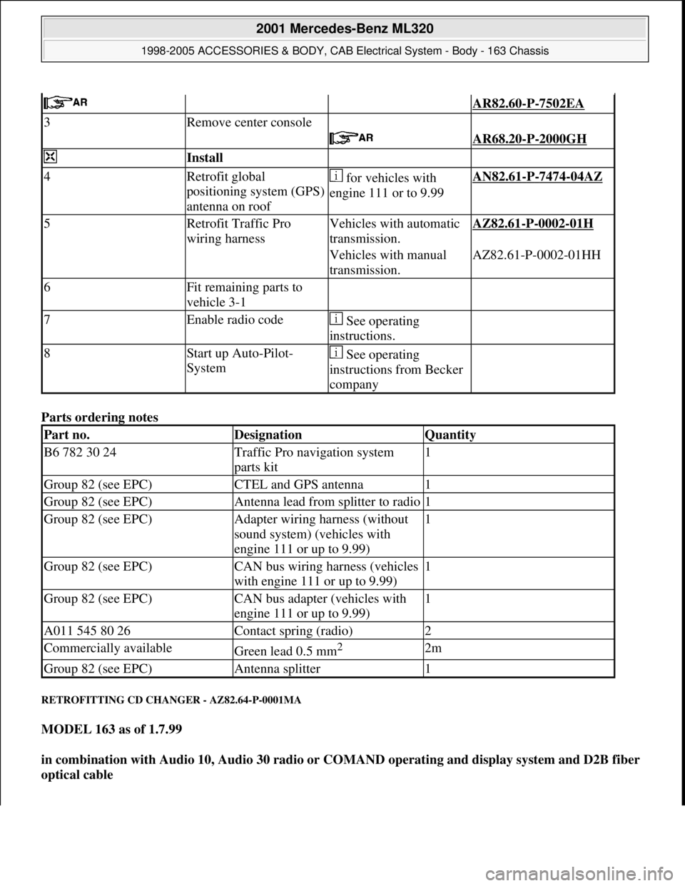
Part no.DesignationQuantity
B6 782 30 24Traffic Pro navigation system
parts kit1
Group 82 (see EPC)CTEL and GPS antenna1
Group 82 (see EPC)Antenna lead from splitter to radio1
Group 82 (see EPC)Adapter wiring harness (without
sound system) (vehicles with
engine 111 or up to 9.99)1
Group 82 (see EPC)CAN bus wiring harness (vehicles
with engine 111 or up to 9.99)1
Group 82 (see EPC)CAN bus adapter (vehicles with
engine 111 or up to 9.99)1
A011 545 80 26Contact spring (radio)2
Commercially availableGreen lead 0.5 mm2 2m
Group 82 (see EPC)Antenna splitter1
2001 Mercedes-Benz ML320
1998-2005 ACCESSORIES & BODY, CAB Electrical System - Body - 163 Chassis
me
Saturday, October 02, 2010 3:30:13 PMPage 418 © 2006 Mitchell Repair Information Company, LLC.
Page 1932 of 4133
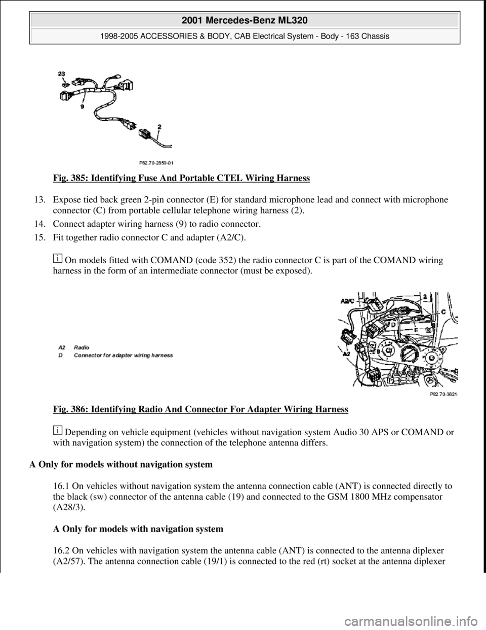
Fig. 385: Identifying Fuse And Portable CTEL Wiring Harness
13. Expose tied back green 2-pin connector (E) for standard microphone lead and connect with microphone
connector (C) from portable cellular telephone wiring harness (2).
14. Connect adapter wiring harness (9) to radio connector.
15. Fit together radio connector C and adapter (A2/C).
On models fitted with COMAND (code 352) the radio connector C is part of the COMAND wiring
harness in the form of an intermediate connector (must be exposed).
Fig. 386: Identifying Radio And Connector For Adapter Wiring Harness
Depending on vehicle equipment (vehicles without navigation system Audio 30 APS or COMAND or
with navigation system) the connection of the telephone antenna differs.
A Only for models without navigation system
16.1 On vehicles without navigation system the antenna connection cable (ANT) is connected directly to
the black (sw) connector of the antenna cable (19) and connected to the GSM 1800 MHz compensator
(A28/3).
A Only for models with navigation system
16.2 On vehicles with navigation system the antenna cable (ANT) is connected to the antenna diplexer
(A2/57). The antenna connection cable (19/1) is connected to the red (rt) socket at the antenna diplexer
2001 Mercedes-Benz ML320
1998-2005 ACCESSORIES & BODY, CAB Electrical System - Body - 163 Chassis
me
Saturday, October 02, 2010 3:30:13 PMPage 437 © 2006 Mitchell Repair Information Company, LLC.
Page 2672 of 4133
Plugs and couplings. with yellow, orange or red housing colors are reserved for safety and restraint systems
(SRS) and roll bars.
Observe the following when repairing couplings for squibs (SRS systems):
The repair area must be between 100 mm and 1000 mm behind the squib. Cables which have already been
repaired are provided with a yellow marking. This is to be applied retroactively to repair lines without color
marking.
Carry out the first repair as close to the plug as possible. In the case of subsequent repairs the old soldered
connectors should be removed and the new ones should be attached behind them, the wiring harness should be
replaced if necessary.
Before cutting through the lines it is absolutely essential to assign the lines to the corresponding pins in
accordance with the wiring diagram. Do not mix up the pin assignment.
The line colors of the repair kit may deviate from the original fitting
Screened lines and light plastic-sheathed cable must never be repaired
In general the following applies to cable repair:
If more than ten lines per branch-off line are damaged, the wiring harness module must be replaced.
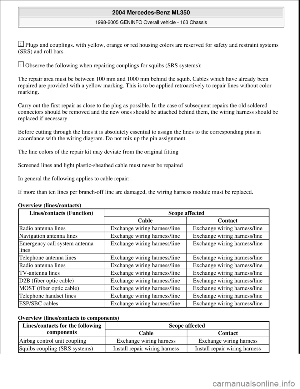
Overview (lines/contacts)
Overview (lines/contacts to components)
Lines/contacts (Function)Scope affected
CableContact
Radio antenna linesExchange wiring harness/lineExchange wiring harness/line
Navigation antenna linesExchange wiring harness/lineExchange wiring harness/line
Emergency call system antenna
linesExchange wiring harness/lineExchange wiring harness/line
Telephone antenna linesExchange wiring harness/lineExchange wiring harness/line
Radio antenna linesExchange wiring harness/lineExchange wiring harness/line
TV-antenna linesExchange wiring harness/lineExchange wiring harness/line
D2B (fiber optic cable)Exchange wiring harness/lineExchange wiring harness/line
MOST (fiber optic cable)Exchange wiring harness/lineExchange wiring harness/line
Telephone handset linesExchange wiring harness/lineExchange wiring harness/line
ESP/SBC cablesExchange wiring harness/lineExchange wiring harness/line
Lines/contacts for the following
componentsScope affected
CableContact
Airbag control unit couplingExchange wiring harnessExchange wiring harness
Squibs coupling (SRS systems)Install repair wiring harnessInstall repair wiring harness
2004 Mercedes-Benz ML350
1998-2005 GENINFO Overall vehicle - 163 Chassis
me
Saturday, October 02, 2010 3:47:44 PMPage 27 © 2006 Mitchell Repair Information Company, LLC.