Page 1830 of 4133

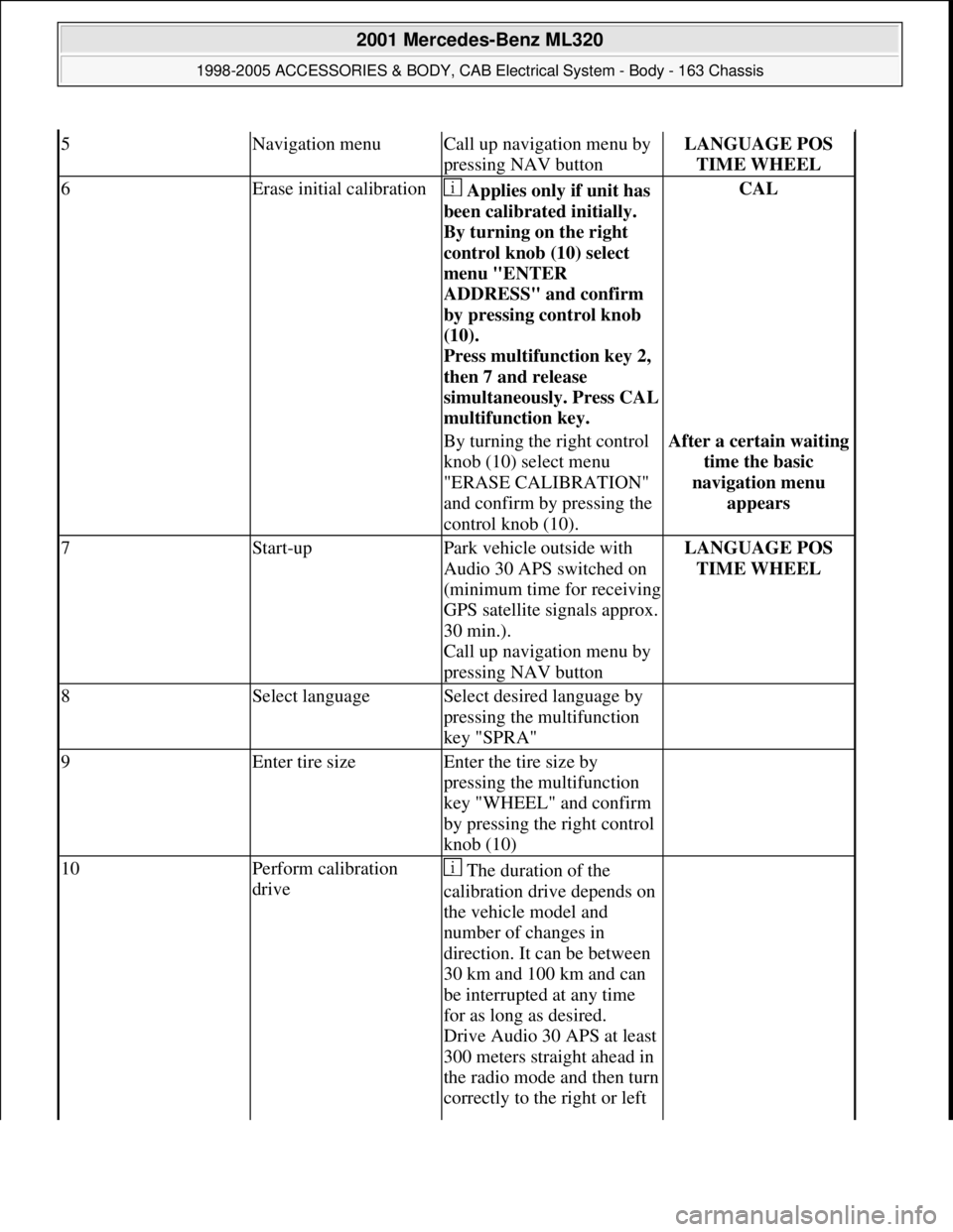
5Navigation menuCall up navigation menu by
pressing NAV buttonLANGUAGE POS
TIME WHEEL
6Erase initial calibration Applies only if unit has
been calibrated initially.
By turning on the right
control knob (10) select
menu "ENTER
ADDRESS" and confirm
by pressing control knob
(10).
Press multifunction key 2,
then 7 and release
simultaneousl
y. Press CAL
multifunction key.
CAL
By turning the right control
knob (10) select menu
"ERASE CALIBRATION"
and confirm by pressing the
control knob (10).After a certain waiting
time the basic
navigation menu
appears
7Start-upPark vehicle outside with
Audio 30 APS switched on
(minimum time for receiving
GPS satellite signals approx.
30 min.).
Call up navigation menu by
pressing NAV buttonLANGUAGE POS
TIME WHEEL
8Select languageSelect desired language by
pressing the multifunction
key "SPRA"
9Enter tire sizeEnter the tire size by
pressing the multifunction
key "WHEEL" and confirm
by pressing the right control
knob (10)
10Perform calibration
drive The duration of the
calibration drive depends on
the vehicle model and
number of changes in
direction. It can be between
30 km and 100 km and can
be interrupted at any time
for as long as desired.
Drive Audio 30 APS at least
300 meters straight ahead in
the radio mode and then turn
correctly to the right or left
2001 Mercedes-Benz ML320
1998-2005 ACCESSORIES & BODY, CAB Electrical System - Body - 163 Chassis
me
Saturday, October 02, 2010 3:30:11 PMPage 335 © 2006 Mitchell Repair Information Company, LLC.
Page 1831 of 4133

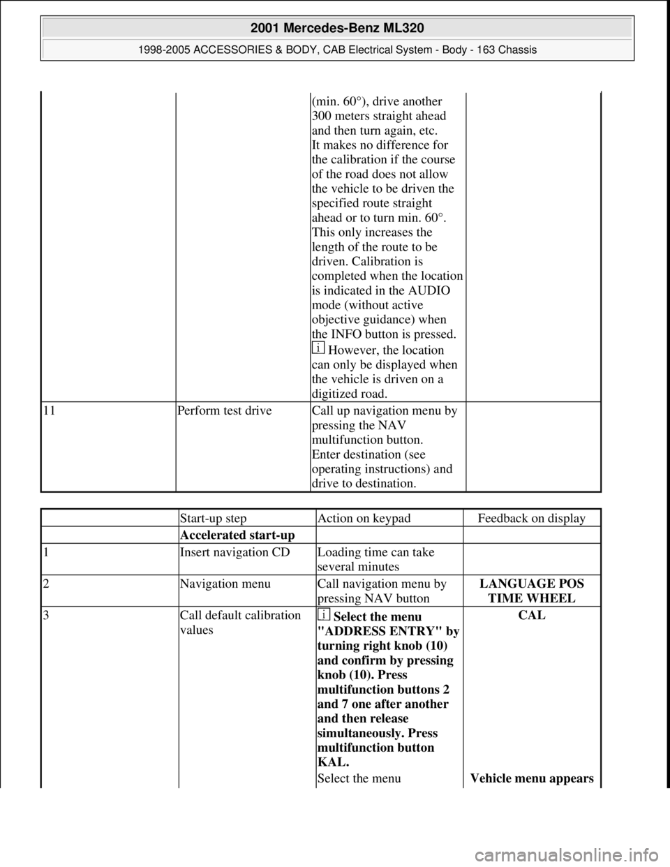
(min. 60°), drive another
300 meters straight ahead
and then turn again, etc.
It makes no difference for
the calibration if the course
of the road does not allow
the vehicle to be driven the
specified route straight
ahead or to turn min. 60°.
This only increases the
length of the route to be
driven. Calibration is
completed when the location
is indicated in the AUDIO
mode (without active
objective guidance) when
the INFO button is pressed.
However, the location
can only be displayed when
the vehicle is driven on a
digitized road.
11Perform test driveCall up navigation menu by
pressing the NAV
multifunction button.
Enter destination (see
operating instructions) and
drive to destination.
Start-up stepAction on keypadFeedback on display
Accelerated start-up
1Insert navigation CDLoading time can take
several minutes
2Navigation menuCall navigation menu by
pressing NAV buttonLANGUAGE POS
TIME WHEEL
3Call default calibration
values Select the menu
"ADDRESS ENTRY" b
y
turning right knob (10)
and confirm by pressing
knob (10). Press
multifunction buttons 2
and 7 one after another
and then release
simultaneously. Press
multifunction button
KAL.
CAL
Select the menu Vehicle menu appears
2001 Mercedes-Benz ML320
1998-2005 ACCESSORIES & BODY, CAB Electrical System - Body - 163 Chassis
me
Saturday, October 02, 2010 3:30:11 PMPage 336 © 2006 Mitchell Repair Information Company, LLC.
Page 1890 of 4133

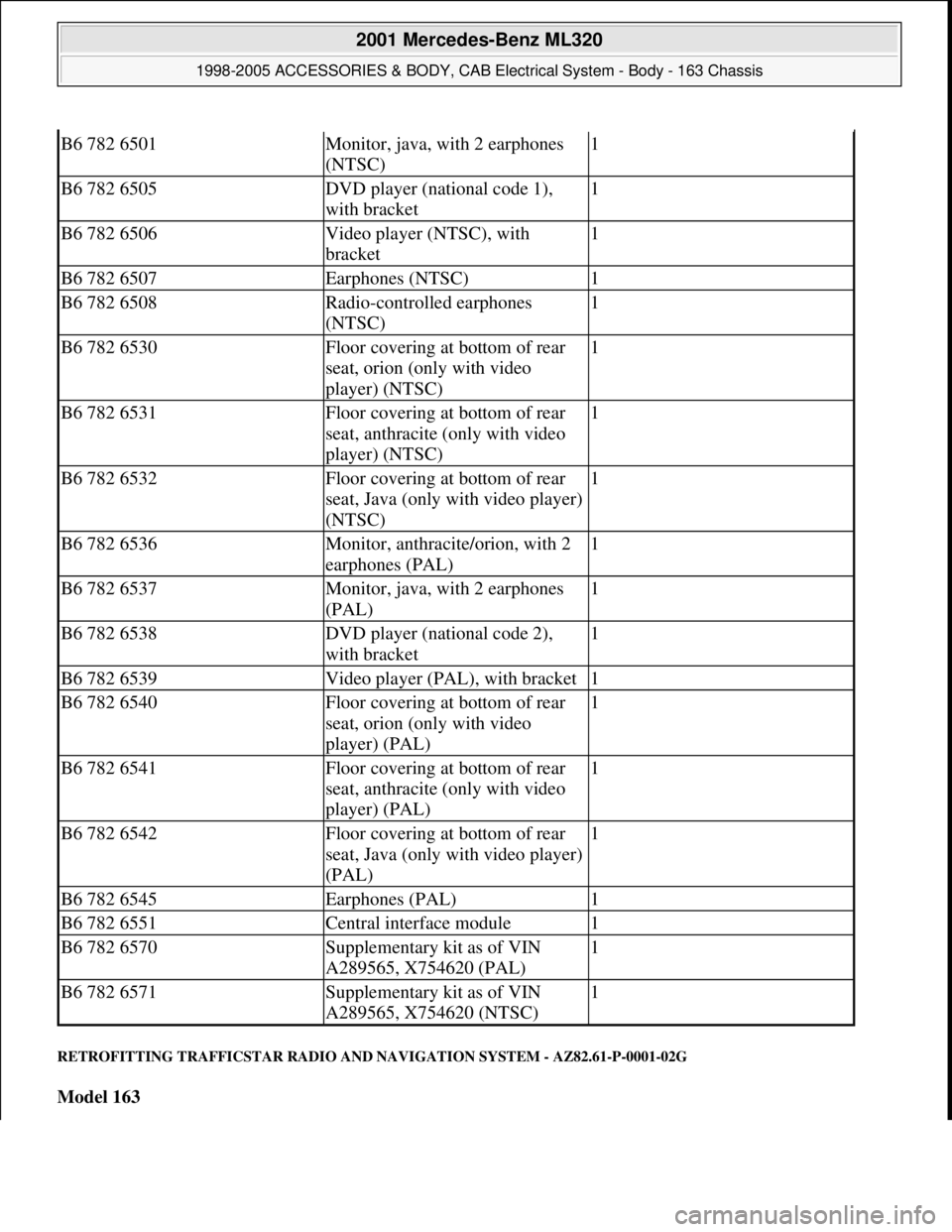
RETROFITTING TRAFFICSTAR RADIO AND NAVIGATION SYSTEM - AZ82.61-P-0001-02G
Model 163
B6 782 6501Monitor, java, with 2 earphones
(NTSC)1
B6 782 6505DVD player (national code 1),
with bracket1
B6 782 6506Video player (NTSC), with
bracket1
B6 782 6507Earphones (NTSC)1
B6 782 6508Radio-controlled earphones
(NTSC)1
B6 782 6530Floor covering at bottom of rear
seat, orion (only with video
player) (NTSC)1
B6 782 6531Floor covering at bottom of rear
seat, anthracite (only with video
player) (NTSC)1
B6 782 6532Floor covering at bottom of rear
seat, Java (only with video player)
(NTSC)1
B6 782 6536Monitor, anthracite/orion, with 2
earphones (PAL)1
B6 782 6537Monitor, java, with 2 earphones
(PAL)1
B6 782 6538DVD player (national code 2),
with bracket1
B6 782 6539Video player (PAL), with bracket1
B6 782 6540Floor covering at bottom of rear
seat, orion (only with video
player) (PAL)1
B6 782 6541Floor covering at bottom of rear
seat, anthracite (only with video
player) (PAL)1
B6 782 6542Floor covering at bottom of rear
seat, Java (only with video player)
(PAL)1
B6 782 6545Earphones (PAL)1
B6 782 6551Central interface module1
B6 782 6570Supplementary kit as of VIN
A289565, X754620 (PAL)1
B6 782 6571Supplementary kit as of VIN
A289565, X754620 (NTSC)1
2001 Mercedes-Benz ML320
1998-2005 ACCESSORIES & BODY, CAB Electrical System - Body - 163 Chassis
me
Saturday, October 02, 2010 3:30:12 PMPage 395 © 2006 Mitchell Repair Information Company, LLC.
Page 1891 of 4133
System illustration
Fig. 311: Identifying Trafficstar Radi o And Navigation System Components
TrafficStar wiring harness with sound
2001 Mercedes-Benz ML320
1998-2005 ACCESSORIES & BODY, CAB Electr ical System - Body - 163 Chassis
me
Saturday, October 02, 2010 3:30:12 PMPage 396 © 2006 Mitchell Repair Information Company, LLC.
Page 1895 of 4133
Fig. 320: Identifying GPS Antenna Connector And GPS Antenna Lead
16. Install counter plug (7) from TrafficS tar wiring harness (4) to radio connector (A2) and wrap with felt (c).
Fig. 321: Identifying Radio Connector And Counter Plug
17. Plug radio connector (A) and yellow sound connector (C1) as well as blue GPS antenna connector (C3)
from TrafficStar wiring harness (4) into Traf ficStar radio and navigation system (1).
18. Connect radio antenna.
19. Install TrafficStar (1) ra dio and navigation system.
Fig. 322: Identifying GPS Antenna Connector And Sound Connector
RETROFITTING TRAFFICSTAR RADIO AND NAVIGATION SYSTEM - AZ82.61-P-0001-02I
2001 Mercedes-Benz ML320
1998-2005 ACCESSORIES & BODY, CAB Electr ical System - Body - 163 Chassis
me
Saturday, October 02, 2010 3:30:12 PMPage 400 © 2006 Mitchell Repair Information Company, LLC.
Page 1896 of 4133
Model 163
System illustration
Fig. 323: Identifying Trafficstar Radio And Navigation System Components
TrafficStar wiring harness without sound
2001 Mercedes-Benz ML320
1998-2005 ACCESSORIES & BODY, CAB Electrical System - Body - 163 Chassis
me
Saturday, October 02, 2010 3:30:12 PMPage 401 © 2006 Mitchell Repair Information Company, LLC.
Page 1900 of 4133
Fig. 331: Identifying CAN Bus Adapter And Lead
14. Connect brown and black wire (br, sw) from GPS ante nna lead (3) with brown and black lead (br, sw)
from TrafficStar wiring harness (4) and slide flat plug insulations together.
15. Attach flat plug connectors and GPS antenna lead (3) to TrafficStar wiring harness (4) with felt.
Fig. 332: Identifying GPS Antenna Connector And GPS Antenna Lead
16. Install counter plug (7) from TrafficS tar wiring harness (4) to radio connector (A2) and wrap with felt (c).
Fig. 333: Identifying Radio Connector And Counter Plug
17. Connect radio connector (A) and GPS antenna conn ector (C3) with TrafficStar radio and navigation
system (1).
18. Connect radio antenna.
2001 Mercedes-Benz ML320
1998-2005 ACCESSORIES & BODY, CAB Electr ical System - Body - 163 Chassis
me
Saturday, October 02, 2010 3:30:12 PMPage 405 © 2006 Mitchell Repair Information Company, LLC.
Page 1901 of 4133
19. Install TrafficStar (1) ra dio and navigation system.
Fig. 334: Identifying GPS Antenna Connector And Sound Connector
CARRYING OUT START-UP AND FU NCTION CHECK - AZ82.61-P-0001-04A
Models 129, 140, 163, 168, 170, 202, 208, 210
System description
Fig. 335: Identifying Trafficstar Display Fi eld, Automatic Button And Mode Button
Step 5 for initial start-up only applies for equipment which has already been installed in a vehicle and on
which initial calibration has been performed.
Start-up step
Entry with TrafficStar
keysFeedback on TrafficStar display field
1Start engine
2Switch on TrafficStarEnter code (see CODE
card) with
multifunction buttons
below the numbers on
the display field.CODE 1 2 3 4 5 6 7 8
3Insert navigation CD
into TrafficStarLoading time approx. 1
min.
2001 Mercedes-Benz ML320
1998-2005 ACCESSORIES & BODY, CAB Electr ical System - Body - 163 Chassis
me
Saturday, October 02, 2010 3:30:12 PMPage 406 © 2006 Mitchell Repair Information Company, LLC.