Page 652 of 1395
Shift Control Solenoid Valve A/B Assembly
Test
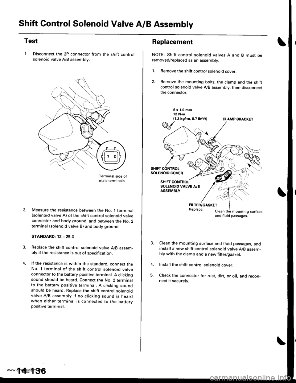
'1. Disconnect the 2P connector from
solenoid valve Ay'B assembly.
the shift control
Terminalsade ofmale terminals
Measure the resistance between the No. 1 terminal(solenoid valve A) of the shift control solenoid valve
connector and body ground, and between the No. 2terminal (solenoid valve B) and body ground.
STANDARD: 12 - 25 O
Replace the shift control solenoid valve A,/B assem-bly if the resistance is out of specification.
lf the resistance is within the standard. connect theNo, I terminal of the shift control solenoid valveconnector to the battery positive terminal. A clickingsound should be heard. Connect the No. 2 terminalto the battery positive te.minal. A clicking soundshould be heard. Replace the shift control solenoidvalve A/B assembly if no clicking sound is heardwhen either terminal is connected to the battervpositive terminal.
14-136
Replacement
NOTE: Shift control solenoid valves A and B must beremoved/replaced as an assembly.
1. Remove the shift control solenoid cover.
2. Remove the mounting bolts, the clamp and the shiftcontrol solenoid valve Ay'B assembly, then disconnect
the connector.
6x1.0mm12 N.m{1.2 k9 .m,8.7 lbtft}CLAMP ARACKET
FILTER/GASKETReplace.Clean the mounling surfaceand fluid passages.
Clean the mounting surface and fluid passages. andinstall a new shift control solenoid valve Ay'B assem-bly with the clamp and a new filter/gasket.
Install the shift control solenoid cover.
Check the connector for rust, dirt. or oil, and recon-nect it securely.
w
SHIFT CONTROLSoLENO|O COVEn
SHIFT CONTROLSOLENOID VALVE A/BASSEMBLY
\--
qK
-!t'">,,
www.emanualpro.com
Page 654 of 1395
Mai nshaft /Cou ntershaft
Linear Solenoid AssemblySpeed Sensors
Replacement
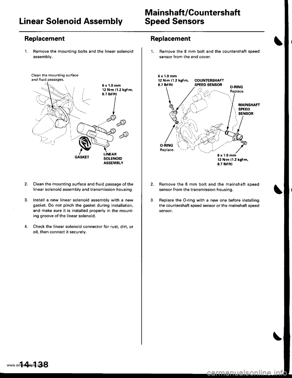
'1. Remove the mounting bolts and the linear solenoid
assemblY.
Clean the mounting surfaceand fluid passages.
6x1.0mm12 N.m (1.2 kg{.m.8.7 tbtftl
@
@
GASKET
Clean the mounting surface and fluid passage of the
linear solenoid assembly and transmission housing.
Install a new linear solenoid assemblv with a new
gasket. Do not pinch the gasket during installation,
and make sure it is installed properly in the mount-
ing groove of the linear solenoid.
Check the linear solenoid connector for rust. dirt, or
oil, then connect it securelv.
14-138
Replacement
1. Remove the 6 mm bolt and the countershaft sDeed
sensor from the end cover.
\
5x1.0mm12 N.m 11.2 kgf.m, COUNTERSHAFT8.7 rbf.frl SPEED SENSOR
O.RINGReplace.
12 N'm 11.2 kgl.m,8.7 tbf.ftl
Remove the 6 mm bolt and the mainshaft speed
sensor from the transmission housing.
Replace the O-ring with a new one before installing
the countershaft speed sensor or the mainshaft speed
sensor,
6x1.0mm
www.emanualpro.com
Page 656 of 1395
A/T Gear Position Switch
Replacement
@ Make 3ure lifts, iacks, and safety stands
ar€ placod properly lsoo soction 1).
1. Raise the front of the vehicle, and support it with
safety stands (see section 1).
2. Set the parking brake, and block both rear wheels
securely.
3. Shift to E position.
Remove the A/T gear position switch connector
from the connector bracket, then disconnect it.
Remove the AfI gear position switch harness clamp.
5x1.0mm12Nm11.2kgf.m,8.7 tbf.fttBRACIGT
14-140
6. Remove the harness clamp from the end cover,
then remove the Aff gear position switch cover and
Ay'T gear position switch.
A/T GEAF POSITIONswrTcH covER6x1.0mm12 N.m 11.2 kgt m.8.7 lbf.ftl
1.Set the IVT gear position switch to E position. The
AfI gear position switch clicks in E position.
POSmON
6x1.0mm12 N.m
{1.2 kg{.m,8.7 lbtftl
swlTcH
www.emanualpro.com
Page 657 of 1395
8. Set the control shaft to E] position. then install the
A,/T gear position switch on it.
CONTROL SHAFT
Install the Ay'T gear position switch cover and har-
ness clamp on the end cover.
Connect the A,/T gear position switch connector.
then install it on the connector bracket.
Turn the ignition switch ON (ll). Move the shift lever
through all gears, and check the AfI gesr position
switch synchronization with the A/T gear position
indicator.
9.
10.
11.
A/TGEARPOSMON A/T GEAR POSITIONINDICATOR INDICATOR'99 - 00 MODELS '�97 - 98 MOOELS
12, Start the engine. Move the shift lever through all
gears. and verify the following:
. The shift lever cannot be moved to E] position
from E position unless the shift lever is pulled.
. The engine will not start in any position other
than E or E.. The back-up lights come on when the shift lever
is in El position.
14-141
www.emanualpro.com
Page 660 of 1395
Interlock System
Interlock Control Unit Input Test
SRS components are located in this area. Review the SRS component locations, precautions, and procedures in the SRS
section (24) before performing repairs or service.
'1. Remove the instrument panel lower cover (see section 20).
2. Disconnect the 8P connector from the interlock control unit.
3. Inspect the connector and connector terminals to be sure they are all making good contact.
. lf the terminals are bent, loose, or corroded, repair them as necessary, and recheck the system
. lf the terminals look OK, make the following input tests at the connector.
- lf a test indicates a problem, find and correct the cause, then recheck the system
- lf all the input tests prove OK, substitute a known-good control unit, and recheck the system. lf the check is OK,
the control unit must be faulty; replace it.
NOTE: lf the shift lock solenoid clicks when the ign ition switch is tu rned ON (ll) while pressing the brake pedal withthe
shift lever in E position, the shift lock system is OK. lf the shift lever cannot be shifted from E position. test the A/T
gear position switch.
14-144
www.emanualpro.com
Page 662 of 1395
lnterlock System
Key Interlock Solenoid Test
SRS comoonents are located in this area. Review the SRS
component locations, precautions. and procedures in the
SRS section (24) before pertorming repairs or service.
1. Remove the instrument panel lower cover (see sec-
tion 20).
2. Disconnect the ignition switch 6P connector at the
connector holder.
6P CONNECTOR
14-146
3. Check for continuitv between the terminals in each
key position according to the table.
IGNITION SWITCH 6P CONNECTOR
Check that the key cannot be removed with power
connected to the No. 5 terminal and ground connected
to the No. 3 terminal.
lf the key cannot be removed. the key interiock
solenoid is OK.
lf the key can be removed, replace the steering
lock assembly (the key interlock solenoid is not
available separately).
\____________r{r4
Position
lgnition
switch
ACC 0)
Key pushed ino---'o
Key releasedo----o
www.emanualpro.com
Page 663 of 1395
Shift Lock Solenoid Test
SRS components are located in this area. Review the SRS
component locations, precautions, and procedures in the
SRS section (24) before performing repairs or service,
'1. Remove the instrument panel lower cover (see sec-
tion 20).
2. Remove the steering column covers (see section 17).
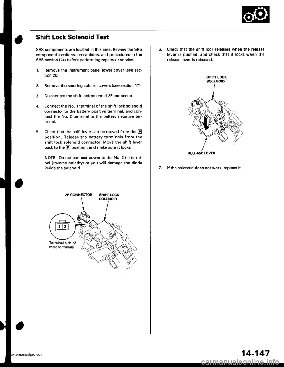
3. Disconnect the shift lock solenoid 2P connector.
Connect the No. 1 terminal of the shift lock solenoid
connector to the battery positive tgrminal, and con-
nect the No. 2 terminal to the battery nogative ter-
mrnal.
Check that the shift lever can be moved from the E
oosition. Release the batterv terminals from the
shift lock solenoid connector. Move the shift lever
back to the E position, and make sure it locks.
NOTE: Do not connect power to the No. 2 (-) termi-
nal {reverse polarity) or you will damage the diode
inside the solenoid.
2P CONNECTOR SHIFT LOCK
6. Check that the shift lock releases when the release
lever is pushed, and check that it locks when the
release lever is released,
7. lf the solenoid does not work, replace it.
14-147
www.emanualpro.com
Page 664 of 1395
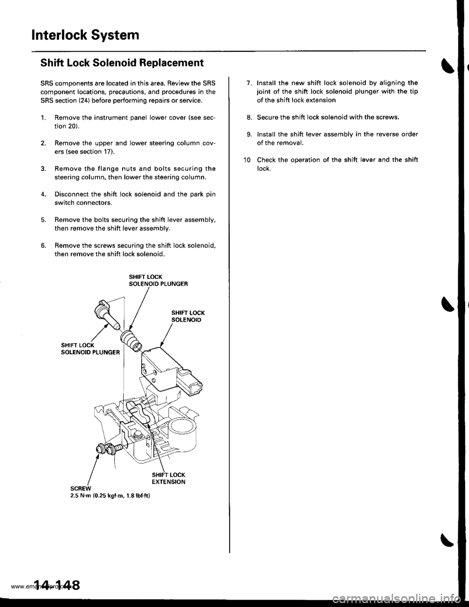
Interlock System
Shift Lock Solenoid Replacement
SRS components are located in this area. Review the SRS
component locations, precautions, and procedures in the
SRS section (24) before performing repairs or service.
'L Remove the instrument panel lower cover (see sec-
tion 20).
2. Remove the upper and lower steering column cov-
ers (see section 17).
3. Bemove the flange nuts and bolts securing the
steering column, then lower the steering column.
4. Disconnect the shift lock solenoid and the park pin
switch connectors.
Remove the bolts securing the shift lever assembly,
then remove the shift lever assemblv.
Remove the screws securing the shift lock solenoid,
then remove the shift lock solenoid.
2.5 N.m {0.25 kgl.m, 1.8lbf.ft}
14-148
7.Install the new shift lock solenoid by aligning the
joint of the shift lock solenoid plunger with the tip
of the shift lock extension
Secure the shift lock solenoid with the screws,
Install the shift lever assembly in the reverse order
of the removal.
Check the operation of the shift lever and the shift
lock.
9.
10
www.emanualpro.com