Page 754 of 1395
Transfer Assembly
Transfer Housing Roller Bearing
Replacement
NOTE; Coat all parts with ATF du.ing reassembly.
1. Remove the roller bearing from the transfer hous
Ing.
Install the new roller bearing using the special tools
and a press.
TRANSFER HOUSING
ATTACHMENT,62x68mm07746 - 0010500
14-238
Transfer Cover A Bearing Outer
Race Replacement
NOTE: Coat all parts with ATF during reassembly.
1. Remove the tapered roller bearing outer race from
transfer cover A by heating the cover to almost
212"F llOO"Cl using a heat gun. Do not heat the
cover over 212"F (100"C).
Install the 68 mm thrust shim in transfer cover A.
Install the tapered roller bearing outer race using
the special tools and a p.ess.
www.emanualpro.com
Page 759 of 1395
10.
11.
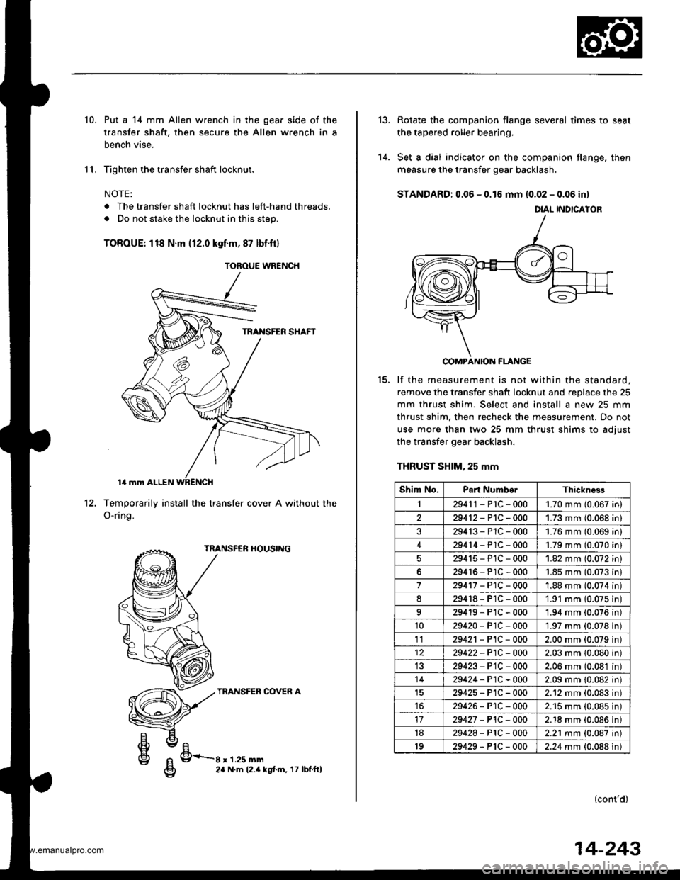
Put a 14 mm Allen wrench in the gear side of the
transfer shaft, then secure the Allen wrench in a
bench vise.
Tighten the transfer shaft locknut.
NOTE:
. The transfer shaft locknut has left-hand threads.
. Do not stake the locknut in this step.
TOROUE: 118 N'm 112.0 kgf.m, 87 lbf.ftl
Temporarily install the transfer cover A without
O-ring.
TRANSFER HOUSING
TRANSFER COVER A
the12.
g/FrE24 N.m 12.4 kgt.m, 17 lbf.ftl
TOROUE WRENCH
tt el
g 9-r'r.ru--g 24 N.m 12.4 |
14-243
13.
14.
Rotate the companion flange several times to seat
the tapered roller bearing.
Set a dial indicator on the companion flange, then
measure the transfer gear backlash.
STANDARD: 0.06 - 0.16 mm {0.02 - 0.06 inl
COMPANION FLANGE
lf the measurement is not within the standard.
remove the transfer shaft locknut and replace the 25
mm thrust shim. Select and install a new 25 mm
thrust shim. then recheck the measurement. Do not
use more than two 25 mm thrust shims to adiust
the transfer gear backlash.
THRUST SHIM, 25 mm
(cont'd)
15.
DIAL INOICATOR
Shim No.Part NumborThickness
I29411-P1C-0001.70 mm (0.067 in)
229412-P1C-0001.73 mm (0.068 in)
29413-P1C-0001.76 mm (0.069 in)
429414-P1C-0001.79 mm (0.070 in)
29415-PlC-0001.82 mm (0.072 in)
629416-P1C-0001.85 mm (0.073 ini
729417-PlC-0001.88 mm (0.074 in)
d29418-P1C-0001.91 mm {0.075 in)
29419-P1C-0001.94 mm (0.076 in)
1029420-PtC-0001.97 mm (0.078 in)
1129421 - P1C - 0002.00 mm (0.079 in)
29422-P1C-0002.03 mm 10.080 in)
29423-P'1C-0002.06 mm (0.081 in)
1429424-P1C-0002.09 mm 10.082 in)
29425-P1C-0002.12 mm (0.083 in)
1629426-P1C-0002.'15 mm (0.085 in)
1729427 - P1C -O002.18 mm (0.086 in)
1829428-PlC-0002.21 mm (0.087 in)
1929429-P1C-0002.24 mm {0.088 in)
www.emanualpro.com
Page 763 of 1395
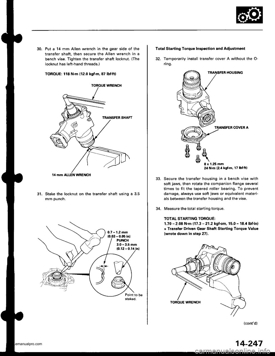
30. Put a 14 mm Allen wrench in the gear side of the
transfer shaft. then secure the Allen wrench in a
bench vise. Tighten the transfer shaft locknut. {The
locknut has left-hand threads,)
TOROUE: 118 N.m (12.0 kgf.m, 87 lbt.ft)
Stake the locknut on the transfer shaft using a 3.5
mm ounch.
al
14 mm ALI-EN WRENGH
0.7 - 1.2.nm{0.0:1- 0.C5 in}PU CH3.0 - 3.5 rnm
Total Starting Tolqu€ Insp€ction and Adiustment
32. TemDorarilv install transter cover A without the O-
flng.
HOUSING
TMNSFER COVER A
e
€
v
E- 8x1.25mm24 N'm {2.i1kgt'm, r? bt'ftl
Secure the transfer housing in a bench vise with
soft jaws, then rotate the companion flange several
times to fit the tapered roller bearing. To prevent
damage, always use soft jaws or equivalent materi-
als betlveen the transfer housing and the vise.
Measure the total starting torque.
TOTAL STARTING TOROUE:
1.70 - 2.08 N.m {17.3 - 21.2kgl.cm,15.0 - 18.i1 lbf.in}
+ Transler Driven Gear Sh8ft Starting Torque Value
lwroto down in step 27).
(cont'd)
5J.
34.
14-247
www.emanualpro.com
Page 764 of 1395
Transfer Assembly
35.
Reassembly (cont'dl
36.
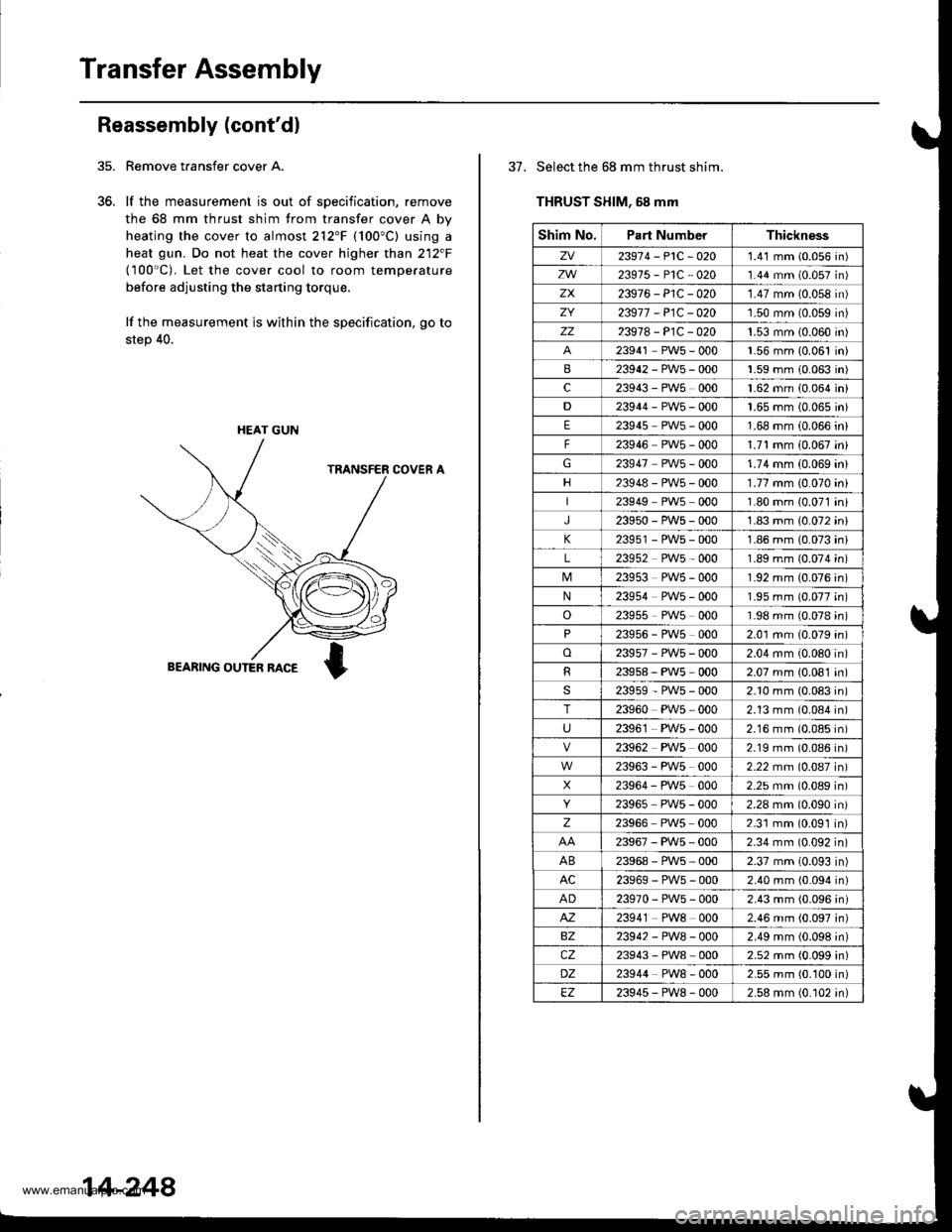
Remove taansfer cover A.
lf the measurement is out of specification, remove
the 68 mm thrust shim from transfer cover A by
heating the cover to almost 212"F (100"C) using a
heat gun. Do not heat the cover higher than 212"F(100'C). Let the cover cool to room temperature
before adjusting the starting torque,
lf the measurement is within the specification, go to
step 40.
HEAT GUN
14-248
37. Select the 68 mm thrust shim.
THRUST SHIM, 58 mm
Shim No.Part NumberThickness
zv23974-P1C-O201.41 mm (0.056 in)
zw23975-P1C-O201.44 mm (0.057 in)
zx23976-P1C-020'1.47 mm (0.058 in)
ZY23977 - P1C - O201.50 mm (0.059 in)
zz23978-P1C-0201.53 mm 10.060 in)
23941 PW5 - 000'1.56 mm {0.061 in)
B23942-PWs-0001.59 mm 10.063 in)
c23943 - PWs 0001.62 mm (0.064 in)
D23944-PW5-0001.65 mm {0.065 in}
E23945 PWs - 0001.68 mm (0.066 in)
F23946 PWs - 0001.71 mm (0.067 in)
G23947 PWs - 0001.74 mm (0.069 ini
23948-PW5-0001.77 mm (0.070 ini
23949 PW5 0001.80 mm (0.071 in,
J23950-PWs-0001.83 mm {0.072 ini
K23951 - PWs - 0001.86 mm (0.073 in
L23952 PW5 - 0001.89 mm (0.074 in
23953 PWs - 0001.92 mm (0.076 in
N23954 PW5 - 0001.95 mm (0.077 in
o23955 PW5 0001.98 mm (0.078 in
P23956 - PWs 0002.01 mm (0.079 in
o23957-PW5-0002.04 mm (0.080 in
R23958, PWs 0002.07 mm (0.081 in
s23959-PW5-0002.10 mm (0.083 in
T23960 PW5 - 0002.13 mm (0.084 in
U2396'1 PW5 - 0002.16 mm (0.085 in
23962 PWs 0002.19 mm (0.086 in
23963 - PW5 0002.22 mm (0.087 in
X23964 - PW5 0002.25 mm (0.089 in
23965 PW5 - 0002.28 mm (0.090 in
z23966 PWs 0002.31 mm (0.091 in
23967-PWs-0002.34 mm (0.092 in
AB23968-PWs-0002.37 mm (0.093 in)
AC23969-PWs-0002.40 mm (0.094 in)
AD23970-PW5-0002.43 mm (0.096 in)
M23941 PW8 0002.46 mm (0.097 in)
BZ23942-PW8-0002.49 mm (0.098 in)
cz23943 - PW8 0002.52 mm (0.099 in)
DZ23944 PW8 - 0002.55 mm (0.100 in)
EZ23945-PW8-0002.58 mm (0.102 in)
www.emanualpro.com
Page 765 of 1395
38. Install the 68 mm thrust shim using the special
tools.
PRESSDRIVER07743 - 001 0000
ATTACHMENT,62x68mrr|077a6 - (x)10500
39.After replacing the 68 mm thrust shim. recheck and
make sure the total starting torque is within the
specification.
AEARING OUTER RACE
40. Install the new O-rings on transfer covers A and B,
then installthe covers on the transfer housing
6x1.0mm12 N.m 11.2 kgt.D,8.7 rbf.ftlTRANSFEN COVER B
O.RINGReplace.
8 r 1.25 rnm24 N.m 12.4 kgl.m, 17 lbf'ftl
Replace.
www.emanualpro.com
Page 772 of 1395
Transmission
Reassembly lcont'd)
44.
Set the park lever in @ position, then verify that thepark pawl engages the park gear.
lf the pawl does not engage fully, check the distancebetween the park pawl shaft and the park leverroller pin (see page 14-231).
Tighten the lock bolt and bend the lock tab.
1o tbf'frl
PARK GEAR
46. Install the end cover with two dowel pins and a newgasket {twelve bolts).
TOROUE: 12 N.m (1.2 kgf.m, 8.7 tbf.ft)
6 r 1.O mm
PARK PAWL
6 x 1.0 mm EOLT HOLE{Used in step 50.)
END COVER
14-256
A/T GEAR FOSMON SWNCH
47. Install the control lever assemblv on the controlshaft. (4WDl
6x1.0mm14 N.m 11.4 kg{.m,10 tbf.ftl
48.
CONTROL LEVERASSEMBLY
Set the A/f gear position switch to E] position.
NOTE: The Aff gear position switch cticks in N]position,
www.emanualpro.com
Page 773 of 1395
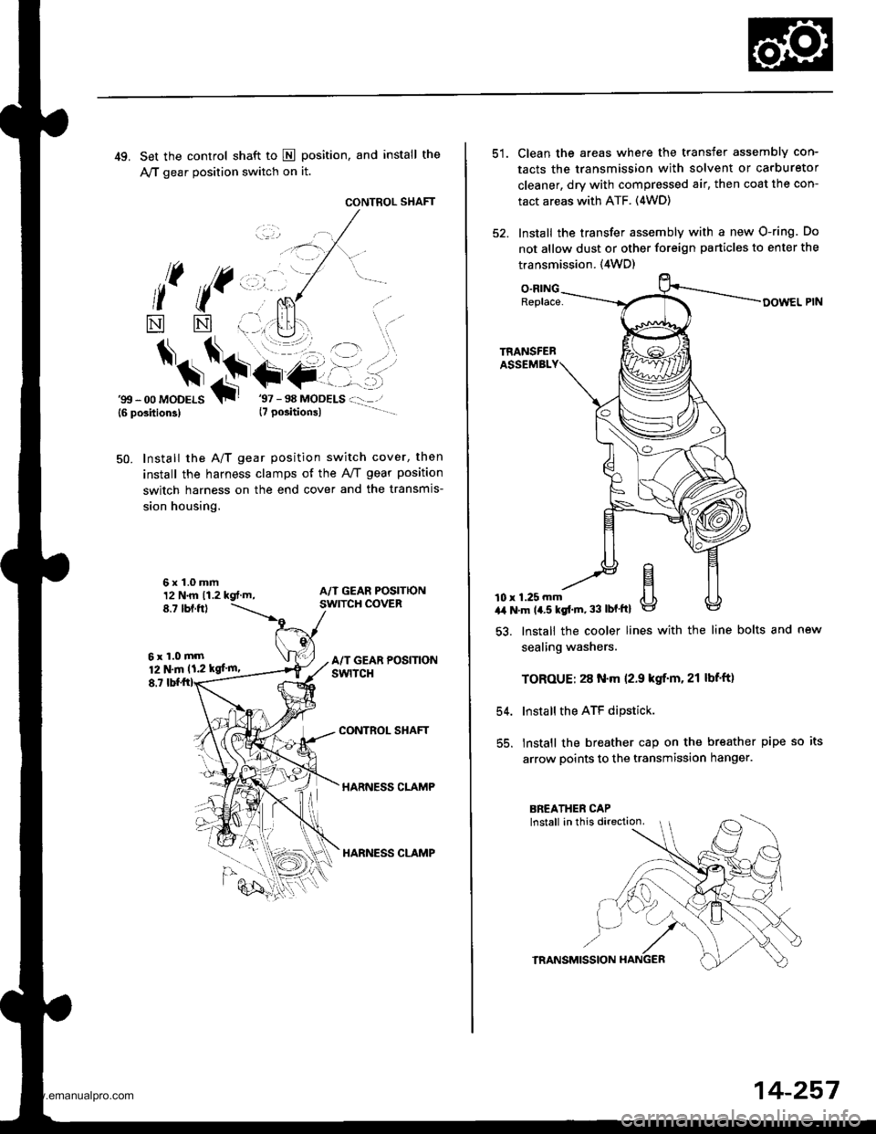
49. Set the control shaft to E position, and install the
A,/T gear position switch on it.
CONTROL SHAFT
l( ((,,, ,.
*
$*\.t+-
NN
6x1.0mm12 N.m 11.2 kgt.m,8.7 tbf.ftl
6xl.0mm12 N.m 11.2 kgf'm,
8,7
'gtt - 00 MoDELS{6 position3}T
Install the A/T gear position switch cover, then
install the harness clamps of the AviT gear position
switch harness on the end cover and the transmis-
sion housing.
50.
CONTROL SHAFT
HARNESS CLAMP
HARNESS CLAMP
Clean the areas where the transfer assembly con-
tacts the transmission with solvent or carburetor
cleaner, dry with compressed air, then coat the con-
tact areas with ATF. (4WD)
Install the transfer assembly with a new O-ring. Do
not allow dust or other foreign particles to enter the
transmission. {4WD)
O.RINGReplace-
10 r 1.25 mma,a N'm 14.5 kgt'm, 33 lbf'ftl
54.
55.
lnstall the cooler lines with the line bolts and new
sealing washers.
TOROUE: 28 N.m 12.9 kgif'm. 21 lbf'ft)
Install the ATF dipstick.
lnstall the breather cap on the breather pipe so its
arrow points to the transmission hanger.
TRANSMISSION
14-257
www.emanualpro.com
Page 776 of 1395
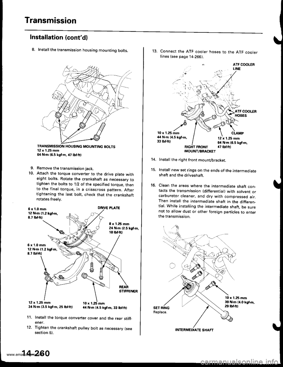
Transmission
Installation (cont'dl
8. Install the transmission housing mounting bolts.
TRANSMISSION HOUSING MOUNTING BOLTS12 x 1.25 mm54 N.m 16,5 kgf.m, a7 lbtftl
9. Remove the transmission jack.
10. Attach the torque convener to the drive plate witheight bolts. Rotate the crankshaft as necessarv totighten the bolts to 'll2 of the specified torque, thento the final torque, in a crisscross pattern. Aftertightening the last bolt. check that the crankshaftrotates freelv.
6x1.0mln12 N.m (1.2 tgt m,8.t lbf.frl
6x1.0mm12 N.m {1.219{.m,8.7 tbtft,
12 x t.25 mm34 N.m 13.5 kgf.rn,25 lbf.ft)
8 x 1.25 mm2a N.m 12.5 kgf'm,18 tbt.ftl
DRIVE PLATE
STIFFENER
44 N.rn (4.5 kgt m, 33 lbtftl
11.
12.
Install the torque convener cover and the rear stiff_ener.
Tighten the crankshaft pulley bolt as necessary (seesection 5).
14-260
13. Connect the ATF cooler hoses to the ATF coolerlines (see page 14-266).
. ATF COOLERLINE
'i 'l'r',:,.) -
10 x 1.25 mm44 N.m (4.5 kgf.m,33 tbtftl
CLAMP
12 x 1.25 mm64 N.m 16.5 kg{.m,a7 tbt.ftlFRotrtT
15.
16.
't 4.
SET RINGReplace.
MOUNT/ARACKET
Install the right front mounvbracket.
Install new set rings on the ends of the intermediateshaft and the driveshaft.
Clean the areas where the intermediate shaft con_tacts the transmission {differential) with solvent orcarburetor cleaner, and dry with compressed air.Then install the intermediate shaft in the differen_tial, While installing the intermediate shaft, be surenot to allow dust or other foreign panicles to enterthe transmission.
l0 x 1.25 mm39 N.m 14.0 kgt.n,29 tbf.ftl
INTERMEDIATE SHAFT
www.emanualpro.com