Page 386 of 1395

Fuel Supply System
Fuel Gauge
Tssting
NOTE: Refer to section 23 for the fuel gauge system cir-cuit diagram.
'1. Check the No. 25 METER (7.5 A) fuse in the under-dash fuse/relay box before testing.
2. Fold the left rear seat cushion forward, and remove
the base frame cover {see section 20).
3. Remove the access panel from the floor.
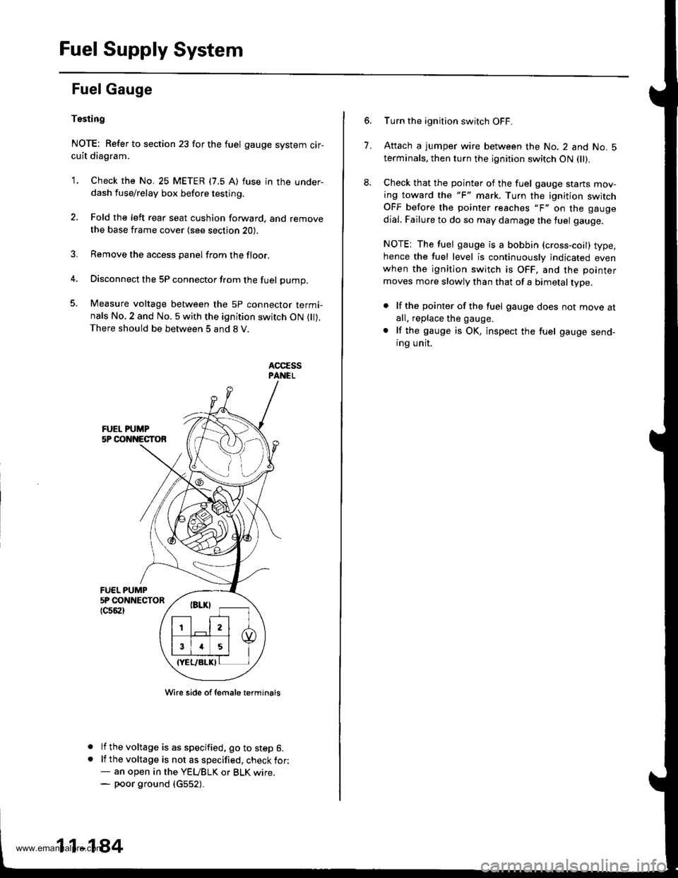
4. Disconnect the 5P connector from the fuel pump.
5. Measure voltage between the 5P connector termi-nals No.2 and No. 5 with the ignition switch ON ( ).There should be between 5 and 8 V.
FUEL PUMP5P CONNECTOR
tc56al
a
a
Wire side of female t€rminals
lf the voltage is as specified, go to step 6.lf the voltage is not as specified, check for:- an open in the YEUBLK or BLK wrre.- poor ground (c552).
11-184
7.
Turn the ignition switch OFF.
Attach a jumper wire between the No. 2 and No. 5terminals, then turn the ignition switch ON fll).
Check that the pointer of the fuel gauge starts mov-ing toward the "F" mark. Turn the ignition switchOFF before the pointer reaches "F" on the gauge
dial. Failure to do so may damage the luel gauge.
NOTE: The fuel gauge is a bobbin (cross-coil) type,hence the fuel level is continuously indicated evenwhen the ignition switch is OFF, and the pointer
moves more slowly than that of a bimetal type.
. lf the pointer of the fuel gauge does not move atall. replace the gauge.
. lf the gauge is OK, inspect the fuel gauge send-ing unit.
www.emanualpro.com
Page 387 of 1395
Fuel Gauge Sending Unit
Tgsting
@ Do not smoke while working on tho fuel
systom. Keop open flamo 8waY from your work araa.
1. Fold the left rear seat cushion forward, and remove
the base frame cover (see section 20).
2. Remove the access panel.
3. With the ignition switch OFF. disconnect the 5P con-
nector from the fuel pump.
4. Relieve fuel pressure (see page 11-178).
5. Disconnect the fuel lines.
6. Remove the fuel pump,
7. Measure the resistance between the No. 2 and No. 5
terminals at E (EMPTY), 1/2 (HALF FULL) and F (FULL)
by moving the float.
lf you do not get the above readings, replace the
fuel pump.
11-185
www.emanualpro.com
Page 389 of 1395

PGM-FI Main Relay
Description
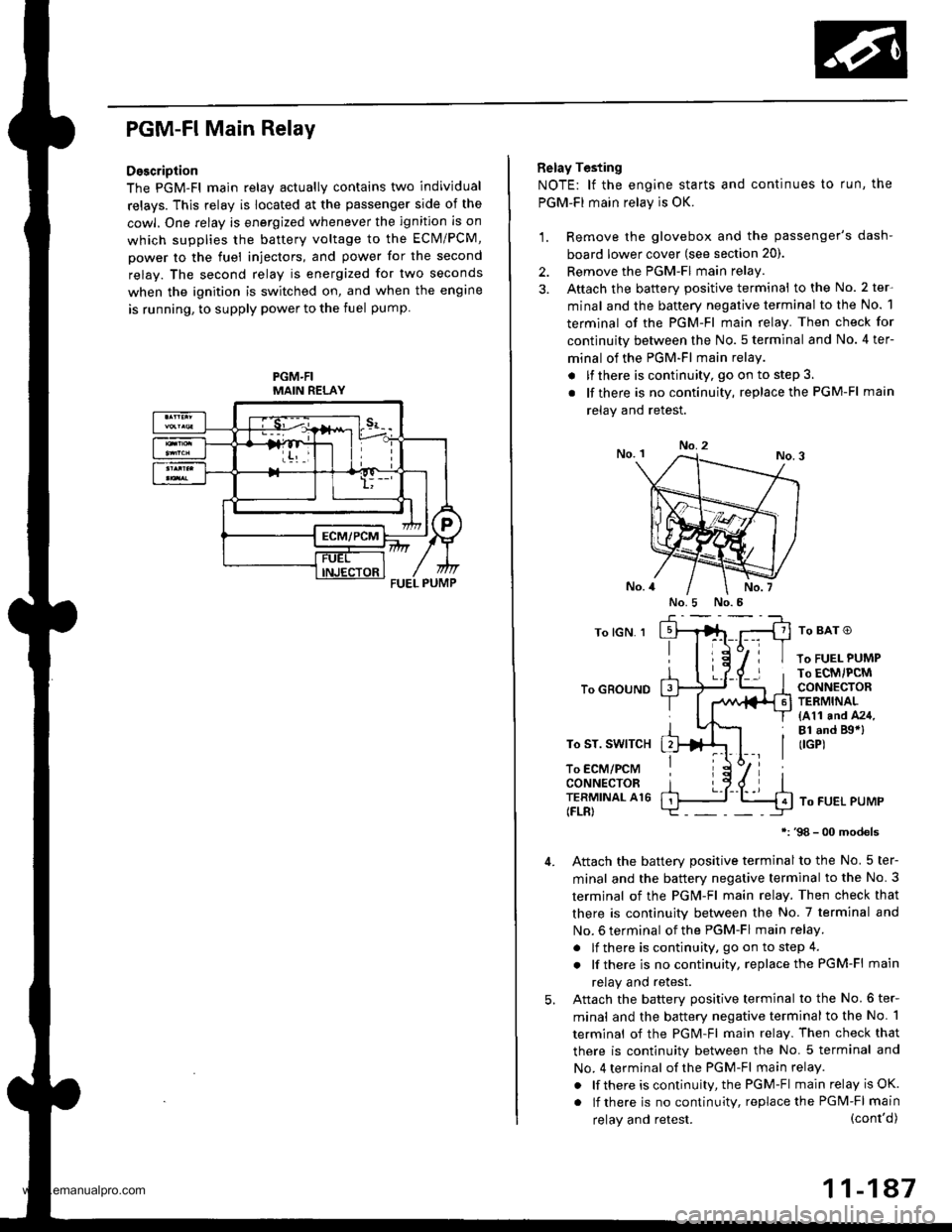
The PGM-Fl main relav actuallv contains two individual
relays. This relay is located at the passenger side of the
cowl. One relay is energized whenever the ignition is on
which supplies the battery voltage to the ECM/PCM,
power to the fuel injectors, and power for the second
relay. The second relay is energized for two seconds
when the ignition is switched on, and when the engine
is running, to supply power to the fuel pump
PGM.FIMAIN RELAY
Belay Testing
NOTE: lf the engine starts and continues to run, the
PGM-FI main relay is OK.
1. Remove the glovebox and the passenger's dash-
board lower cover (see section 20).
2. Remove the PGM-FI main relay
3. Aftach the battery positive terminal to the No. 2 ter-
minal and the battery negative terminal to the No. 1
terminal of the PGM-Fl main relay. Then check for
continuity between the No. 5 terminal and No. 4 ter-
minal of the PGM-FI main relay
. lfthere is continuity, go on to step 3.
. lf there is nocontinuity, replacethe PGM-Fl main
relav and retest.
No.2
To lGN. 1
To GROUND
To ST. SWITCH
To ECM/PCMCONNECTORTERMINAL A16(FLR)
To BAT O
To FUEL PUMPTo ECM/PCMCONNECTORTERMINAL(411 and A24,Bl .nd Bgal(IGP)
To FUEL PUMP
98 - 00 models
Attach the batterv Dositive terminal to the No. 5 ter-
minal and the battery negative terminal to the No. 3
termjnal of the PGM-Fl main relay. Then check that
there is continuity between the No. 7 terminal and
No. 6 terminal of the PGM-FI main relay.
. lf there is continuity, go on to step 4.
. lf there is nocontinuity, replacethe PGM-Fl main
relay and retest.
Attach the batterv oositive terminal to the No.6 ter-
minal and the battery negative terminal to the No. 1
terminal of the PGM-Fl main relay. Then check that
there is continuitv between the No. 5 terminal and
No. 4 terminal of the PGM-Fl main relay.
. lf there is continuity, the PGM-Fl main relay is OK.
. lf there is nocontinuity, replacethe PGM-FI main
5.
(cont'd)
11-147
No.5 No.5
relay and retest.
www.emanualpro.com
Page 393 of 1395

Fuel Tank
Replacement
1. Relieve the fuel pressure (see page 11-178).
2. Fold the left rear seat cushion forward, and remove the base frame cover {see section 20).
3. Remove the access panel from the floor.
4. Disconnect the 5P connector 1C562) and 6P connector (C580) ('98-00 models)'
5. Disconnect the fuel return hose and quick-connect fittings {see page 11-175}
6. Jack up the vehicle, and support it with jackstands.
7. Remove the middle floor beam.
8. Remove the drain bolt, and drain the fuel into an approved contaaner.
g. Disconnect the hoses (see page 11-173, 174). slide back the clamps. then twist hoses as you pull, to avoid damaging
them.
10. Place a jack, or other suppon, under the tank
11. Remove the strap nuts, and let the straps fall free
12. Remove the fuel tank. lf it sticks on the u ndercoat applied to its mount, carefu lly pry it off the mount,
'13. lnstallthe drain bolt with a new washer, then coat the drain bolt with Noxrust 1248'
Allow the Noxrust to dry for 20 minutes.
14. Install parts in the reverse order of removal.
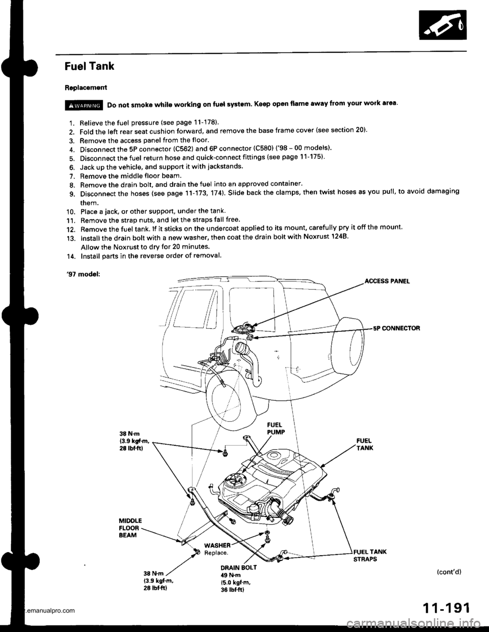
'97 modol:AOCESS PANEL
CONNECTOR
@ Do not smoke while working on fuol systam Keep open flame away from your work area'
DRAIN EOLT49 N.m15.0 kgf'm,36 rbt frl
(cont'd)
1 1-191
www.emanualpro.com
Page 440 of 1395

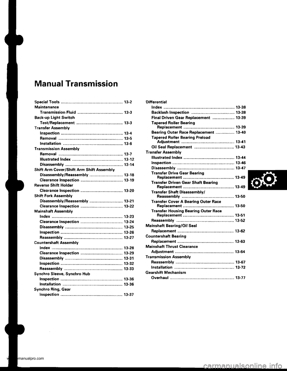
Manual Transmission
Diff€rential
lndex ...................... ......... 13-38
Backlash Inspestion ..,....,.,.....................,......, 13-38
Final Driven Gear Replacement .................... 13-39
Tapered Roller BearingReplacement ............. 13-39
Bearing Outer Race Replacement ......,.,........ 13-i10
Tapered Roller Bearing PreloadAdiustment ............... 13-il1
Oil Seal Reolacement .................................... 13-/l:}
Transfer Assembly
lllustrated Index ............. 13-il4
Inspection ..,....,.,......,...... 13-46
Disassembly ................... 13-47
Transfer Drive Gear BearingReplacement ...,..................,....................... 13-ilg
Transfer Driven Gear Shaft BearingReplacement .............................................. 13-ilg
Transfer Shaft Disassembly/Reassembly .............. 13-50
Transler Cover A Bearing Outer RaceRep1acement.........,.,.,..........,....,...,.........,., 13-50
Transter Housing Bearing Outer RaceReD1acement.............................................. 13-51
Reassembly ..-............,... 13-52
Mainshaft Bearing/Oil Seal
Beplacement .................. 13-62
Countershaft Bearing
Replacement .,,.,.,., ..,...... 13-63
Mainshaft Thrust Clearance
Adiustment .................... 13-6,1
Transmission Assembly
Reassembly .,.,.,.,..,.,....,., 13-67
fnstaffation .,.,.............,... 13-72
Gearshift Mechanism
Overhaul ................ .........13-17
www.emanualpro.com
Page 446 of 1395
Transmission AssemblY
Removal
@FMak. sw. iack" and safety stands are placed propel-
ly, and hoist brackets are attached to collect position
on the engine,
. Apply parking brake and block rear wheels so vehicle
will not roll off stands and lall on you while working
under it.
CAUTION: Use fender covers to avoid damaging painted
surfaces.
1. Disconnect the negative {-) cable first, then the pos-
itive (+) cable from the batterY.
2. Remove the intake air duct and air cleaner houslng
(see section 5).
3. Remove the slave cylinder and clutch hose bracket'
NOTE:
. Do not operate the clutch pedal once lhe slave
cvlinder has been removed.
. Take care not to bend the clutch line.
4. Disconnect the
ground cable.
starter cables and transmission
TRANSMISSIONGROUND CABLE
Disconnect the back-up light switch connector and
wire harness clamP.
(cont'd)
13-7
WIRE HARNESS CLAMP
www.emanualpro.com
Page 449 of 1395
Transmission Assembly
Removal (cont'd)
20. Remove the intermediate shaft.
21.Tie plastic bags over the both ends of the intermedi-
ate shaft. Coat all precision finished surfaces withclean engine oil.
Remove the rear engine stiffene. and clutch hous-Ing cover.
13-10
23. Remove the right front mounvbracket.
RIGHT FRONTMOUNT/BRACKET
Place a jack under the transmission, raise it just
enough to take it off of the mounts, then remove
the transmission mount bracket and transmission
mount.
TRANSMISSION MOUNT
MOUNT BRACKET
www.emanualpro.com
Page 452 of 1395
C) TRANSMISSION HANGER
O INTERLOCK BOLT
O 32 mm SEALING BOLT
@ STEEL BALL {5/16 in.)
€) SPRING 26.1 mm {1.03 in.l
@ wasHER Replace.
O sET BALL scREw
@ WASHER Replace.
€) FLANGE BOLT
@ oll SEAL Replace.
@ DRAIN PLUG
@ WASHER Replace.
@ FILLER PLUG
@ WASHER Replace.
(9 10 x 12 mm DOWEL PIN(D SPRING 25.6 mm 11.01 in.l
€' THRUST WASHER
@} SHIFT ARM C(3 CONICAL SPRING WASHER
@ SPECTAL BOLT
8] SHIFT ARM COVER
@ OIL SEAL Replace.
€! SHIFT LEVER
@I BREATHER CAP(2! SHIFT ARM SHAFT ASSEMBLY
@ SPRING PIN Replace.O SELECT ARM
€!} THRUST WASHER
@ sTH/REVERSE SELECTRETURN SPRING
@ SELECT RETURN SPRING
€) OIL GUTTER PLATE
@ 78 mm SHIM
@ OIL GUIOE M PLATE
@ SELECT SPRING BOLT
@ OIL SEAL Replace.
@ SELECT LEVER
O BACK.UP LIGHT SWITCH
@ WASHER Replace.OO TRANSMISSION HOUSING
13-13
www.emanualpro.com