1997 HONDA CR-V Return valve
[x] Cancel search: Return valvePage 92 of 1395
Cruise Gontrol
Actuator Test (cont'dl
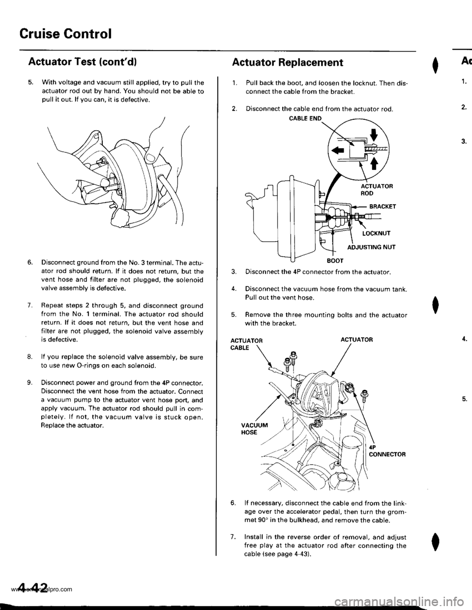
5. With voltage and vacuum still applied, try to pull the
actuator rod out by hand. You should not be able topull it out. lf you can. it is defectrve.
8.
9.
7.
Disconnect ground from the No. 3 terminal. The actu-
ator rod should return. lf it does not return, but the
vent hose and filter are not plugged, the solenoid
valve assembly is defective.
Repeat steps 2 through 5. and disconnect ground
from the No. l terminal. The actuator rod should
return. lf it does not return, but the vent hose and
filter are not plugged, the solenoid valve assembly
is defective.
lf you replace the solenoid valve assembly, be sure
to use new O-rings on each solenoid.
Disconnect power and ground from the 4P connector.
Disconnect the vent hose from the actuator. Connect
a vacuum pump to the actuator vent hose port, and
apply vacuum. The actuator rod should pull in com-pletely. lf not, the vacuum valve is stuck open.
Replace the actuator,
4-42
I
't.
Actuator Replacement
3.
4.
7.
Ar
Pull back the boot. and loosen the locknut. Then dis-
connect the cable from the bracket.
Disconnect the cable end from the actuator rod.
1.
4.
.J.
Disconnect the 4P connector from the actuator.
Disconnect the vacuum hose from the vacuum tank.
Pull out the vent hose.
Remove the three mounting bolts and the actuator
with the bracket.
ACTUATORACTUATOR
CABLE
lf necessary, disconnect the cable end from the link-
age over the accelerator pedal, then turn the grom-
met 90' in the bulkhead. and remove the cable.
Install in the reverse order of removal, and adjust
free play at the actuator rod after connecting the
cable (see page 4-43).
I
6.
I
www.emanualpro.com
Page 326 of 1395
PGM-FI System
Fuel Supply System
[POliil The"""ntool indicates Diagnostic Troubte Code (DTC) p0'171:Thefuet system istoo lean.
[Fo17ZJ rh""""ntool indicates Diagnostic Troubte code {DTc) p0172:Thefuel svstem istoorich.
Description
By monitoring the Long Term Fuel rrim, long term malfunctions in the fuel system will be detected.lf a malfunction has been detected during two consecutive trips, the MIL will come on and DTc p0171 and/or pol72 will bestored.
NOTE: lf someof the DTCS listed below are stored atthesametimeas DTC P017'l and/or p0172, troubleshoot those DTcsfirst, then troubleshoot DTC P0171 and/or PO1i2.
P0107, P0108, P1128, P'1129: MAP Sensor
P0135: Primary HO2S (Sensor 1)Heater
P0137, P0138: Secondary HO2S {Sensor 2)P0141: Secondary H02S (Sensor 2) Heater
P0441*r: EVAP System lnsufficient Purge FtowP1456*,, P'l457 *?i EVAP System Insufficient purge Ftow
Possible Cause
DTC P0171
too lean
*1: '97 model*2: '98 - 00 models
Fuel Pump insufficient flow/pressure
Fuel Feed Line clogged. leaking
Fuel Pressure Regulator stuck openFuel Filter clogged
Fuel Injector clogged, air leakage
Gasoline doesn't meet Owner's Manual spec.Primary HO2S (Sensor 1) deteriorated
Valve Clearance
Exhaust leak
Fuel Pressure Regulator clogged, stuck closedFuel Return Pipe clogged
Fuel Injector leaking
Gasoline doesn't meet Owner's Manual spec.Primary H02S (Sensor 1) deteriorated
EVAP Purge Control Solenoid Valve leaking, stuck openedValve Clearance
DTC P0172
flch
11-124
www.emanualpro.com
Page 381 of 1395
Fuel Injectors
R6placomoni
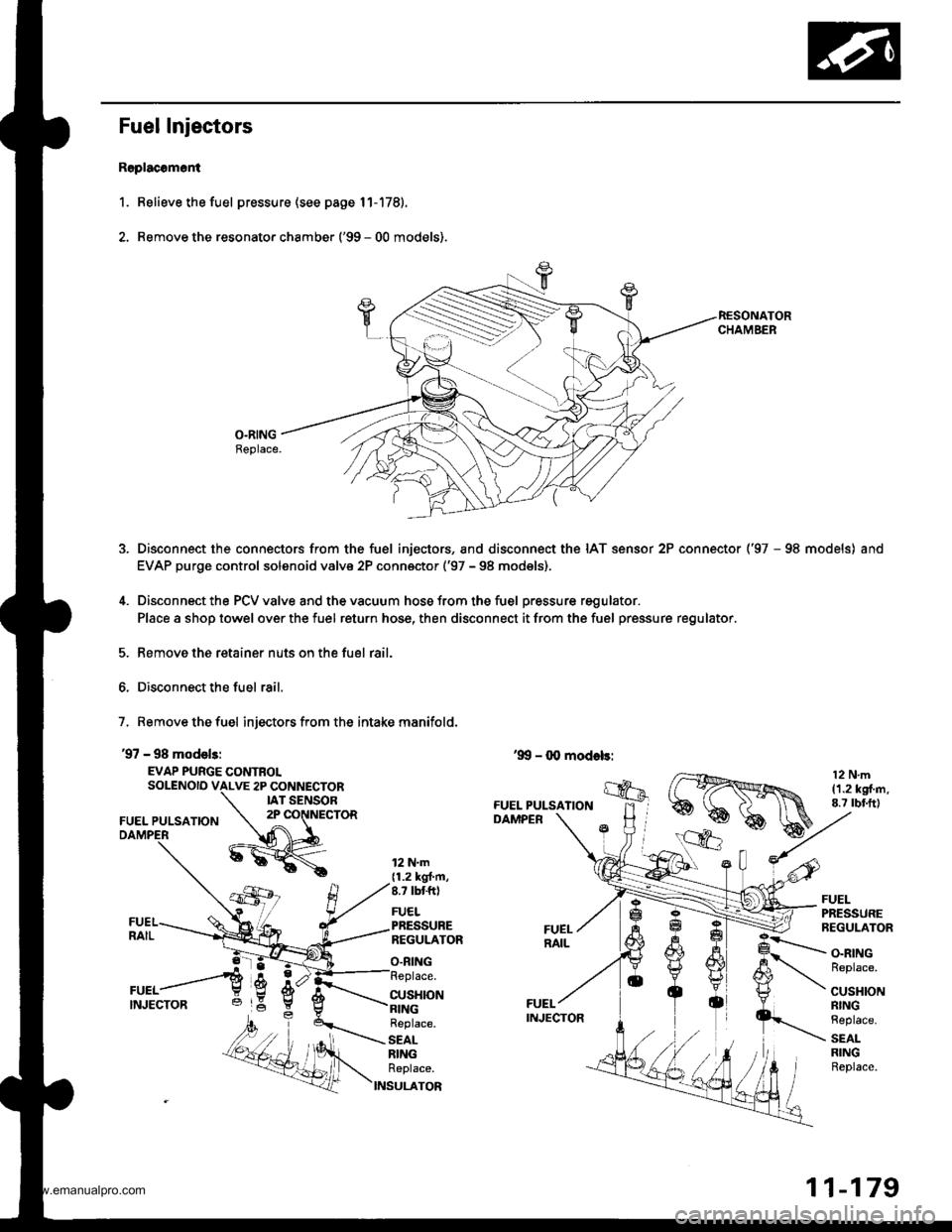
1. Relieve the fuel pressure (see page 11-178).
2. Remove the resonato. chamber ('99 - 00 models).
O.RINGBeplace.
Disconnect the connectors from the fuel injectors, and disconnect the IAT sensor 2P connector ('97 - 98 models) and
EVAP purge control solenoid valve 2P conn€ctor ('97 - 98 models),
Disconnect the PCV valve and the vacuum hose from the fuel pressure regulator.
Place a shop towel over the fuel return hose, then disconnect it from the fuel pressure regulator.
Remove the retainer nuts on the fuel rail.
Disconnect the fuel rail.
7, Remove the fuel injectors from the intake manifold.
'97 - 98 model3:
EVAP PURGE CONTROLSOLENOID VALVE 2P CONNECTORIAT SENSOR
FUEL PULSATION2P CONNECTOR
12 N.m{1.2 kgt'm,8.7 tbtft)
FUELPRESSUREREGULATOR
O.RING
FUELPRESSUREREGULATOR
CUSHION
O.RINGReplace.
CUSHIONRINGReplace.
SEALRINGReplace.
Replace.
SEALRINGReplace.
S
11-179
www.emanualpro.com
Page 382 of 1395
Fuel Supply System
Fuel Injectors {cont'dl
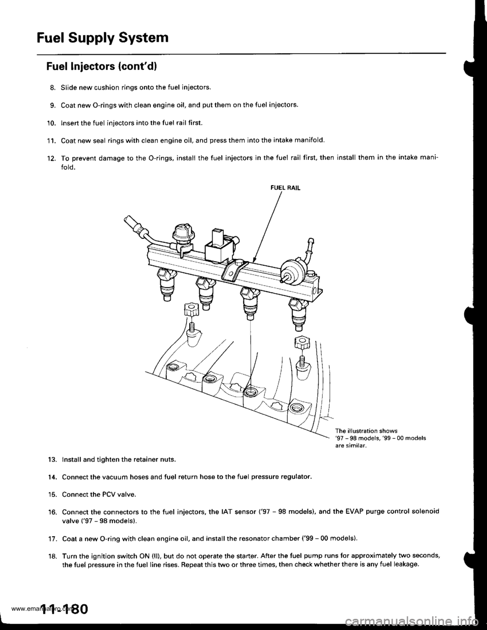
8. Slide new cushion rings onto the fuel injectors.
9, Coat newO-ringswith clean engine oil,and putthem onthefuel iniectors.
'10. lnsert the fuel injectors into the fuel rail first.
11. Coatnewseal ringswithclean engineoil,and press them into the intake manifold
12. To prevent damage to the O-rings, install the fuel injectors in the fuel rail first, then install them in the intake mani-
fold.
FUEL RAIL
The ill!stration shows'97 -98 models,'99 - 00 modelsare similar.
13. lnstall and tighten the retainer nuts.
14. Connect the vacuum hoses and fuel return hose to the fuel pressure regulator.
15. Connect the PCV valve.
16. Connect the connectors to the fuel injectors, the IAT sensor ('97 - 98 models), and the EVAP purge control solenoid
valve {'97 - 98 models).
Coat a new O-ring with clean engine oil, and install the resonator chamber ('99 - 00 models).
Turn the ignition switch ON (ll), but do not operate the starter. After the fuel pump runs for approximately two seconds,
the fuef pressure in the fuel line rises. Repeat this two or three times, then check whether there is any fuel leakage.
11.
18.
1 1-180
www.emanualpro.com
Page 396 of 1395

Intake Air System
Air Cleaner
Air Cleaner Eloment Rsplacomsnt
NOTE: Do not clean the air cleaner element by blowingit off with compressed air,
AIR CLEANER ELEMENTNo.mal conditions:Replace air cleaner element every30,000 miles {48,000 km) or 24months whichever comes first.Severe condition3:Replace air cleaner element every15,000 miles 124,000 km) or 12months whichever comes tirst.
m
11-194
Throttle Cable
Inrpection/Adiustmcnt
1. Stan the engine. Hold the engine at 3,000 rpm with noload (in Park or neutral) until the radiator fan comeson, then let it idle.
2. Check that the throttle cable operates smoothly withno binding or sticking. Repair as necessary,
3. Check cable free play at the throttle linkage. Cabtedeflection should be 10- 12 mm (3/8 - 1l2in.l.
'97 - 98 modols:
CABLEBRACKET
LOCKNUT
DEFLECTION10-12mmBIA- 112 i^l
'99 - 0O modsls:
lf deflection is not within specs, loosen the locknut,turn the adjusting nut untilthe deflection is as speci-fied, then retighten the locknut.
With the cable properly adjusted. check the throttlevalve to be sure it opens fully when you push theaccelerator pedal to the floor. Also check the throt-tle valve to be sure it returns to the idle position
whenever you release the accelerator pedal.
DEFLECTIONl0-12mft
Bla - 112 inl
NUT
www.emanualpro.com
Page 582 of 1395
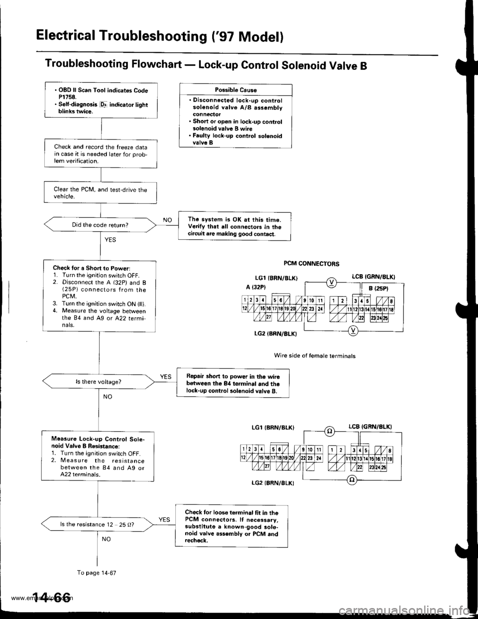
Electrical Troubleshooting ('97 Model)
Troubleshooting Flowchart - Lock-up Control Solenoid Valve B
Possible Causo
. Disconnocted lock-up controlsol€noid valve A/B assembly
. Short or op€n in lock-up control3olenoid vrlve B wi.e. Faulty lock-up control solenoidvalve B
Wire side of female terminals
PCM CONNECTORS
. OBO ll Scan Tool indicates CodeP1758.. Self-diagnosis pr- indicator lightblink3 twice.
Check and record the {reeze datajn case it is needed later for prob,lem verification.
The system is OK at this time.Verify thet dll connectors in thecircuit are making good contact.
Did the code return?
Check tor a Short to Powerl1. Turn the ignition switch OFF.2. Disconnect the A (32P) and B(25P) connectors from thePCM.3. Turn the ignition switch ON {ll).4. Measure the voltage betweenthe 84 and Ag ot A22 tetminals,
Repair short to power in tho wirebstween the 84 terminal and thelock-up control rolenoid valve B.
Measure Lock-up Control Sole-noid Valve B Resistance:1. Turn the ignition switch OFF.2. Measure the resistancebetween the 84 and Ag orA22 terminals.
Check tor loose terminal tit in thePCM connectors, It necessary,subslitute a known-good sole-noid valve assembly o. PCM andrech€ck.
ls the resistance 12 25 O?
To page 14-67
14-66
www.emanualpro.com
Page 609 of 1395
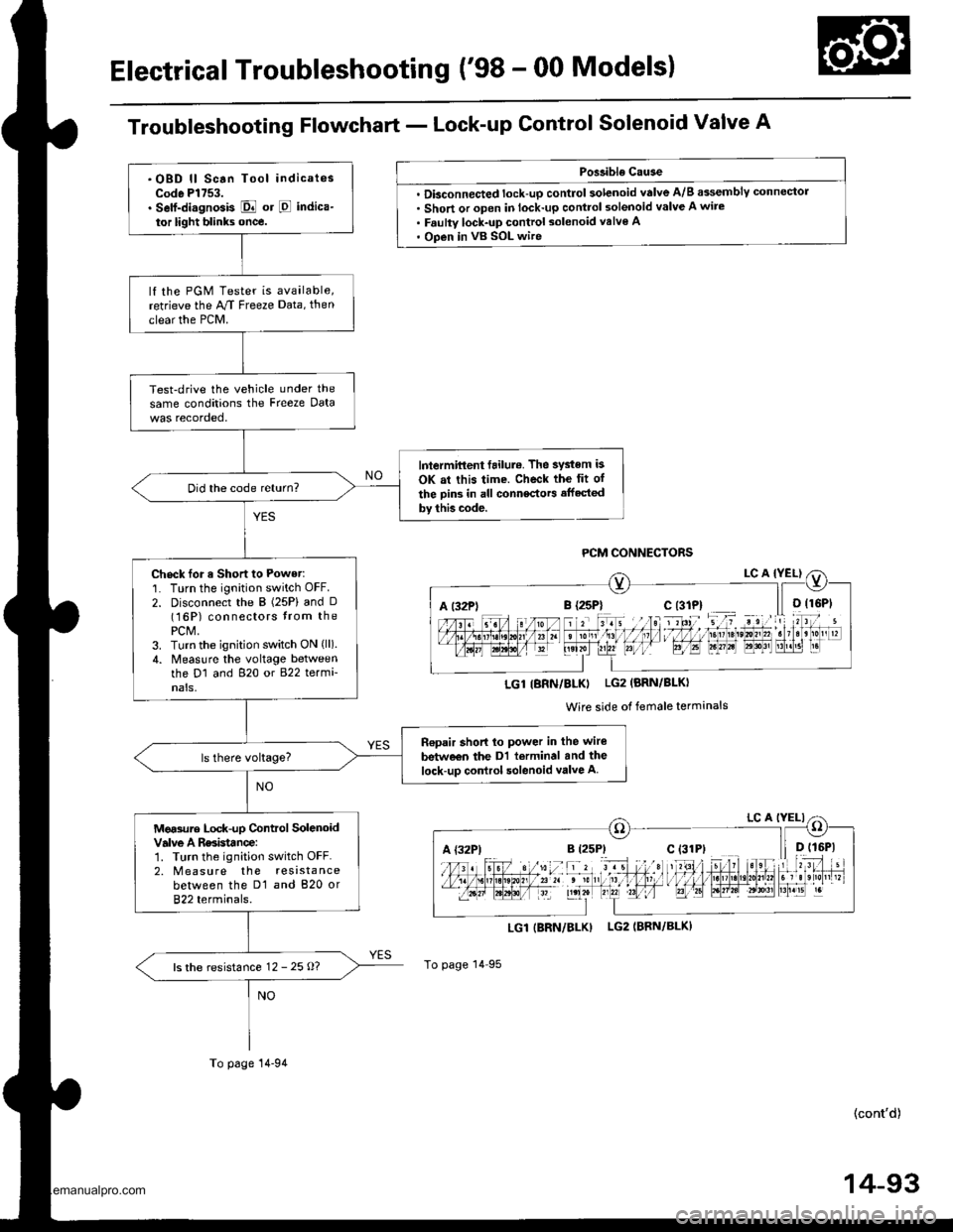
Electrical Troubleshooting ('98 - 00 Models)
Troubleshooting Flowchart - Lock-up Control Solenoid Valve A
Poslible Cause
. Dbconnected lock-up control solenoid valve A/B assemblY connector. Short or open in lock-up control solenoid valve A wire. Faulty lock-up control solenoid valve A' Open in vB SOL wire
LGI|BRN/BLK) LG2IBRN/BLK)
To page 14 95
(cont'd)
14-93
A t32Pli r rriltI l,1 I I ltDrste,0n,,2. t3r B'r!51 r.
LGl IBRN/BLKI LG2 (BRN/BLKI
Wire side of female terminals
A {32P)
.OBD ll Scan Tool indicatesCode Pl753.. Self-di.gnosis E or E indica-
tor light blinks once.
lf the PGM Tester is available,retrieve the M Freeze Data, then
clear the PCM.
Test-drive the vehicle under the
same conditions the Freeze Data
lntermittent failul.. The system is
OK at this time. Check the fit of
the Din3 in all connectors affected
by thb code.
Did the code return?
Check for a Short to Power:'1. Turn the ignition switch OFF.
2. Disconnect the B (25P) and D(16P) connectors trom thePCM,3. Turn the ignition switch ON (ll).
4. Measlre the voltage betweenthe D1 and 820 or 822 termi-nals,
n€pair short lo power in the wire
betw€€n the Dl terminal and the
lock-up control solenoid valve A
Mg.sure Lock-up Control SolenoidValve A Rssistance:1. Turn the ignition switch OFF.2. M easu re the resistancebetween the D1 and 820 or822 terminals.
ls the resistance 12 - 25 o?
To page 14-94
www.emanualpro.com
Page 612 of 1395
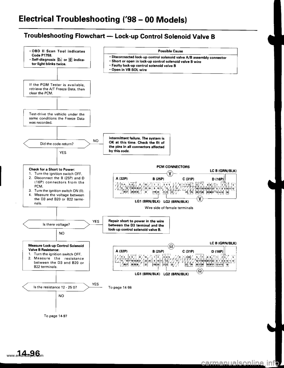
Electrical Troubleshooting ('98 - 00 Models)
Troubleshooting Flowchart - Lock-up Control Sotenoid Valve B
Possibl€ Cause
. Disconnected lock-up control solenoid valve A/8 assembly connector. Short or open in lock-up control solenoid valve B wire. Fauhy lock-up control solenoid valve B. Open in VB SOL wir€
PCM CONNECTORSLC B {GRN/8LKI
LG1{BRN/BLK} I-G2{BRN/BLK)
Wire side of female terminals
A {32P1
To page 14 98
.OBD ll Scan Tool indicatesCode P'l758.. Sell-diagnosis Dl or E indica-tor light blinks twic€.
lf the PGM Tester is available,relrieve the A,/T Freeze Data, thenclear the PCM-
Test-drive the vehicle under thesame conditions the Freeze Data
Interm ittant tailure. The lystem isOK at this time. Check the tii ottho pin3 in all connectors athedby this code.
Did the code return?
Check for a Short to Pow€r:1. Turn the ignition switch OFF.2. Disconnect the B 125P) and D(16P) con nectors lrom thePCM.3. Turn the ignition switch ON 1ll).4. Measure the voltage betlveenthe D3 and 820 or 822 termi-nals.
Repair shon to power in the wirebetween tho D3 terminal and thelook-up control solenoid valve B.
Measure Lock-up Control SolanoidValve B Resistanc€:1. Turn the ignition switch OFF.2. Measure the resistancebetween the D3 and 820 or822 terminals.
ls the resistance 12 - 25 O?
To page 14-97
www.emanualpro.com