Page 973 of 2189

Road Test
NOTE: Warm up the engine to normal operating temperature (the radiator fan com6s on).
1. Apply the parking brake and block the wheels. Start the engine, then shift to the E position while depressing the
brake pedal. Depress the accelerator pedal and release it suddenly. The engine should not stall.
2. Test in E position
Park the vehicle in a slope (approx. 16'). apply the parking brake, and shift into E position. Release the brake; the
vehicle should not move.
3. Test-drive the vehicle on a flat road in the position shown in the table. Check that the engine speeds meet the approx-imate vehicle speeds shown in the table.
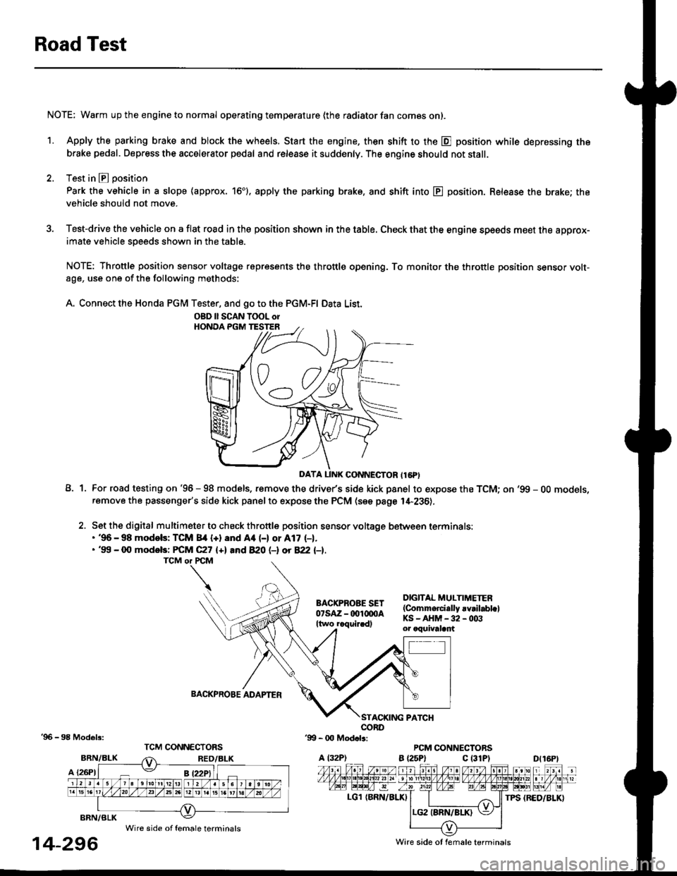
NOTE: Throttle position sensor voltage represents the throttle opening. To monitor the throttle position sensor volt-age, use one of the following methods:
A. Connect the Honda PGM Tester, and go to the PGM-FI Data List.
A1For road testing on '96 - 98 models, remove the drive/s side kick panel to expose the TCM; on '99 - OO models,remove the passenger's side kick panel to expose the PCM (see page l,[-236),
Set the digital multimeter to check throttle position sensor voltage between terminals:. '96 - 98 modols: TCM 84 {+} and Aa (-) or A17 (-1.. '99 - 0O models: FCM C27 {+l and 820 (-l ot 822 l-1.
DIGITAL MULTIMETER(Commerci.lly rvrilabl.lKS-AHM-32-003or oquivalant
BACKPROBE ADAPTER
BRN/BLK
A {26P1
TPS {BED/BLK}
'96 - 98 Models:
BRN/BLK
14-296
OBD ll SCAN TOOL orHONOA PGM TESTER
D{16Pt
Ware side ot female terminals
Wire side of female terminals
Page 1209 of 2189

Diagnostic Trouble Code (DTCI
Diagnostic Trouble Code {DTC) Indication
NOTE: This operation can also be carried out with the Honda pGM Tesrer.
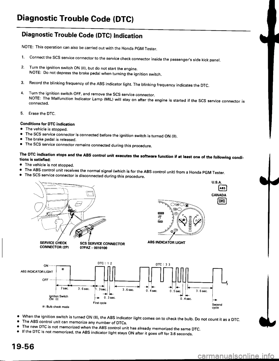
l connect the scs service connector to the service check connector inside the passenger,s side kick panel.
2. Turn the ignition switch ON (||). but do not start the engine.NOTE: Do not depress the brake pedal when turning the ignition switch.
3 Record the brinking frequency of the ABS indicator right. The brinking frequency indicates the DTc.
4, Turn the ignition switch OFF, and remove the SCS service connector.NorE: The Mslfunction Indicator Lamp (MlL) will stay on after the engine is started if the scs service connector isconnected.
5. Erase the DTC.
Condhions for DTC indication. The vehicle is stoDDed.. The SCS service connector is connected before the ignition switch is turned ON fll).. The brake pedal is released.. Th€ SCS service connector remains connected during this procedure
The DTG indication stops 8nd the ABs conltol unit executes the softwaro tunqtion if at least one of the following condi-tions b satisfied:
o The vehicle is not stoDoed.' The ABS control unit receives the normat signal (which is for the ABS controt unit) from a Honda pGM Tester.. The SCS service connector is disconnected during this procedu.e,
u.s.A.
@
CANADA
@
SERVICE CHECKCONNECTOR {2PISCS SERVICE CONNECTOR07PAZ - 0010100
ABS INDICATOR LIGHT
DTC : 3 3
A8S INDICAIOR LIGHT
Snilion swirch
' when the ignition switch is turned oN (ll), the ABs indicator light comes on to check the bulb. Do not count it as a DTc.o The ABS control unit can memorize any number of DTCs.. The new DTC is not memorized when the ABS control unit has already memorized the same DTC,.lftheDTCisnotmemorized,theABSindicatorlightstaysONafteritgoesofffor3.6seconds.
19-56
Page 1210 of 2189

LJDTG Erasure
1.
2.
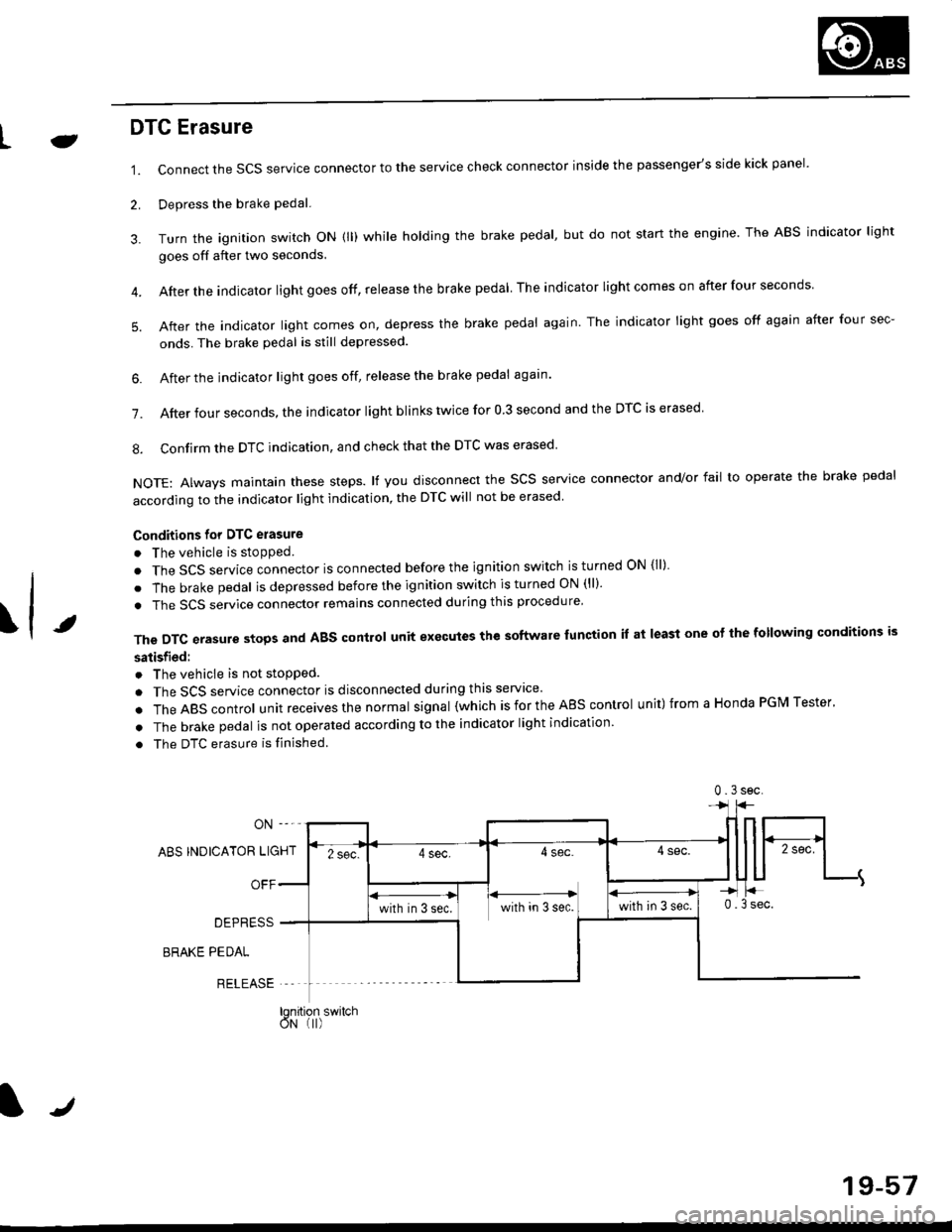
Connect the SCS service connector to the service check connector inside the passenger's side kick panel.
Depress the brake pedal.
Turn the ignition switch oN (ll) while holding the brake pedal, but do not start the engine. The ABS indicator light
goes off after two seconds.
After the indicator light goes off, release the brake pedal The indicator lightcomeson after four seconds
After the indicator light comes on, depress the brake pedal again. The indicator light goes off again after four sec-
onds. The brake pedal is still depressed.
4.
5.
\t
6. After the jndicator light goes off, release the brake pedal again'
7. After four seconds, the indicator light blinks twice for 0 3 second and the DTC is erased
8. Confirm the DTC indication, and check that the DTC was erased
NOTE: Always maintain these steps. lf you disconnect the scs service connector and/or fail to operate the brake pedal
according to the indicator light indication, the DTC will not be erased
Conditions for DTC erasure
o The vehicle is stopped.
. The SCS service connector is connected before the ignition switch is turned ON {ll)
. The brake pedal is depressed before the ignition switch is turned ON (ll)'
. The SCS service connector remains connected during this procedure
The DTC erasure stops and ABS control unit executes the software lunction it at least one ot the following conditions is
satisfied:
o The vehicle is not stopped.
. The SCS service connector is disconnected during this servace'
.TheABscontro|unitreceivesthenormaIsigna|(whichisfortheAEscontro|unit)fromaHondaPGMTester'
. The brake pedal is not operated according to the indicator light indication
. The DTC erasure is finished
ABS INDICATOR LIGHT
OFF
DEPRESS
BRAKE PEDAL
RELEASE
0.3sec
lqnition switchoN (I)
J
19-57
Page 1229 of 2189
ABS Control Unit
Pulsers/Wheel
Sensors
Replacement
1. Remove the right side kick panel.
2. Disconnect the ABS control unit connecrors.
3. Remove the ABS control unit,
4. lnstall the ABS control unit in the reverse order of
removal,
CONNECTORS
19-76
Inspection
Check the front and rear pulser for chipped or dam-aged teeth.
Measure the air gap between the wheel sensor andpulser all the way around while rotating the pulser.
Slandard: 0.4 - 1.0 mm (0.02 - 0.04 in,
NOTE; lf the gap exceeds 1.0 mm (0.04 in), theprobability is a distorted suspension arm which
should be replaced.
Dbc brake typo
0.{ - 1.0 mm(0.02 - 0.04 in)
Drum brake typ6
1.
Page 1289 of 2189
Interior Trim
tReplacement
CAUTION:
. Put on gloves to protect your hands.
o When prying with a flat-tip screwdriver, wrap it with protective tape to prevent damage.
NOTE: Take care not to bend or scratch the trim and panels.
4D:
>: Clip locationsa>,2c >,2'lo >,2E >,2
r*'" n t-lt't
\wi, i
' l ll/
_tr* @,
CENTER PILLARUPPER TRIMREAR PILLARTRIM
LOCK CYLINDER TRIM
tl'
I
E'vBELT UPPERANCHOR(see page 20-85)
Disconnect thehigh mount brakelrght connector.
T SIDE TRIMRemove the rear seat cushion and rearseat side bolster lsee page 20-19]'.
)
lnstallation is the reverse of the removal procedure.
NOTE:
. lf necessary, replace any damaged clips.. Before installing the front seat belt upper anchor
and rear shelf. make sure there are no twists or
kinks in the seat belts.(cont'd)
B>,6
REAR SHELF
k"si
fEFT KICKPANEL
20-59
Page 1290 of 2189
lnterior Trim
Replacement (cont'dl
3D:
>: Clip locationsA>,2CLIP
N;
nt-.l I'"'\R
I
")!
F >, lil
TRIM
B>,3
G >,2H>,2
t
FRONT SEATBELT UPPEBANCHORlsee page 20 86)
SIDE TRIM PANELPROTECTOR
LEFT KICKPANEL
c >,8o>,3
PIVOT BRACKET
{see page 20-80)
lnstallation is the reverse of the removal procedure
NOTE:
. lf necessary, replace any damaged clips'
. Before installing the anchor bolts, make sure there
are no tlvists or kinks in the seat belts'
E >,8
>: Screw, bolt locationsA>,3 8>,6
^l l-lEF\
#, A@ Y
*"0
c>, 1
I "4"
\s
o >,2
l@@
\---
s,4, ffi;T
FRONT PILLARB
eV
REAR SIDESHELF
SIDE TRIMPANELRemove the rear seat-back and
rear seat cushion (see Page 20_80)
Disconnect the rear speaker
connector (both sides,
for some models).
REAR TRIMPANEL
q
RIGHT KICKPANEL
"x-
20-60
Page 1291 of 2189
Il
2Di
>: Clip locationsa>,28>,3
CLIP
G>,4H >,2
D >,3>i Screw location3.4
REAR SHELF
SIOE TRIM PANELRemove the rear seat-back andrear seat cushaon (see page20-a1l.
,
Disconnect the highmount brake light
SEAT BELT
€'
/>"RIGHT KICKPANEL
)
TRIM
nJ'.'rI\ZI
1\f-
F>,8
N 4'dr
SIDE TRIM
LOWER ANCHOR(see page 20-86)
c>, 14E>,2
Installation is the reverse of the removal procedure.
NOTE:
. lf necessary, replace any damaged clips.
. Before installing the anchor bolts and rear shelf,
make sure there are no twists or kinks in the seat
belts.
FRONT PILLAR
FRONT SEATBELT UPPERANCHOR
v
.h,'t6d
\
LEFT KICKPANEL
20-61
Page 1296 of 2189

Carpet
Replacement
SRS components are located in this area. Review the SRS
component locations, precautions, and procedures in the
SRS section {24} before performing repairs or service.
1. Remove:
. Front seat (see page 2O-7 4l
. Rear seat cushion (see pages 20 79, 80, 81)
o Kick panel (see pages 20-59, 60, 61)
o Center pillar lowertrim panel i4D, see page 20-59)
. Front seat belt iower anchor (2Dl3D, see page 20-
86)
. Side trim (see pages 20-59, 60,61)
o Front and rear consoles
. Console panel
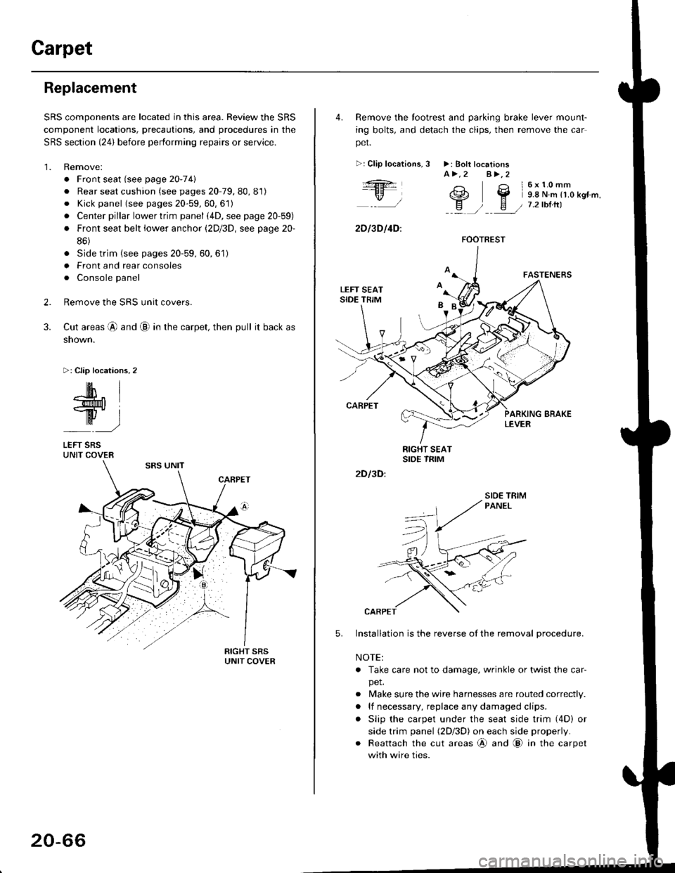
Remove the SRS unit covers.
Cut areas @ and @ in the carpet, then pull it back as
snown.
>: Clip locations,2
2.
3.
-lM- IlMt l
ry-l
LEFT SRSUNIT COVER
20-66
4. Remove the tootrest and parking brake lever mount-
ing bolts, and detach the clips, then remove the car
pet.
>:Clip localions,
:ft
\/l
2D l3D l4D:
3 >: Bolt locationsA>.2 A>,2
3 l6x10mm
e2 Y 9.8 N.m r1.o kgr'm,
H ) E / 7.2tbtrtl::a /
5.
2D I3D:
Installation is the reverse of the removal procedure.
NOTE:
. Take care not to damage. wrinkle or twist the car-
pet.
. Make sure the wire harnesses are routed correctly.
. lf necessary, replace any damaged clips.
. Slip the carpet under the seat side trim (4D) or
side trim panel (2Dl3D) on each side properly.
. Reattach the cut areas @ and @ in the carpet
with wire ties.
FOOTREST
SIOE TBIM