1997 HONDA CIVIC rear control arm
[x] Cancel search: rear control armPage 521 of 2189
Emission Gontrol System
System Description
The emission control system includes a Three Way Cata-lytic Convener (TWC), Exhaust Gas Recirculation (EGR)
system,. Positive Crankcase Ventilation (pCV) system andEvaporative Emission (EVAP) Control system. The emis-sion control system is designed to meet federal and stateemission standards.*: D16Y5 engine
Tailpipe Emission
Inspestion
@@ Do not smoke during ihis procedure. Keepany open flame away from your work area.
1. Start the engine. Hold the engine at 3,000 rpm withno load (in Park or neutral) until the radiator fancomes on. then let it idle.
2. Connect a tachometer.
Check and, if necessary, adjust the idle speed (see
page 11-220 - 223).
Warm up and calibrate the CO meter according to themeter manufacturer's instructions.
Check idle CO with the headlights, heater blower,rear window defogger, cooling fan, and air condition-er off.
NOTE: (Canada) Pull the parking brake lever up.Start the engine, then check that the headlights areoff.
CO mete. should indicate 0.1% maximum.
NOTE: '98 Dl6Y5 engine - lf the idle speed incress-es to 8101 50 rpm, this means the EVAp system ispurging the canister. To stop the purging temporari-ly. raise the engine speed above 1,000 rpm with theaccelerator pedal, then slowly release the pedal.
11-252
eFORWARD -
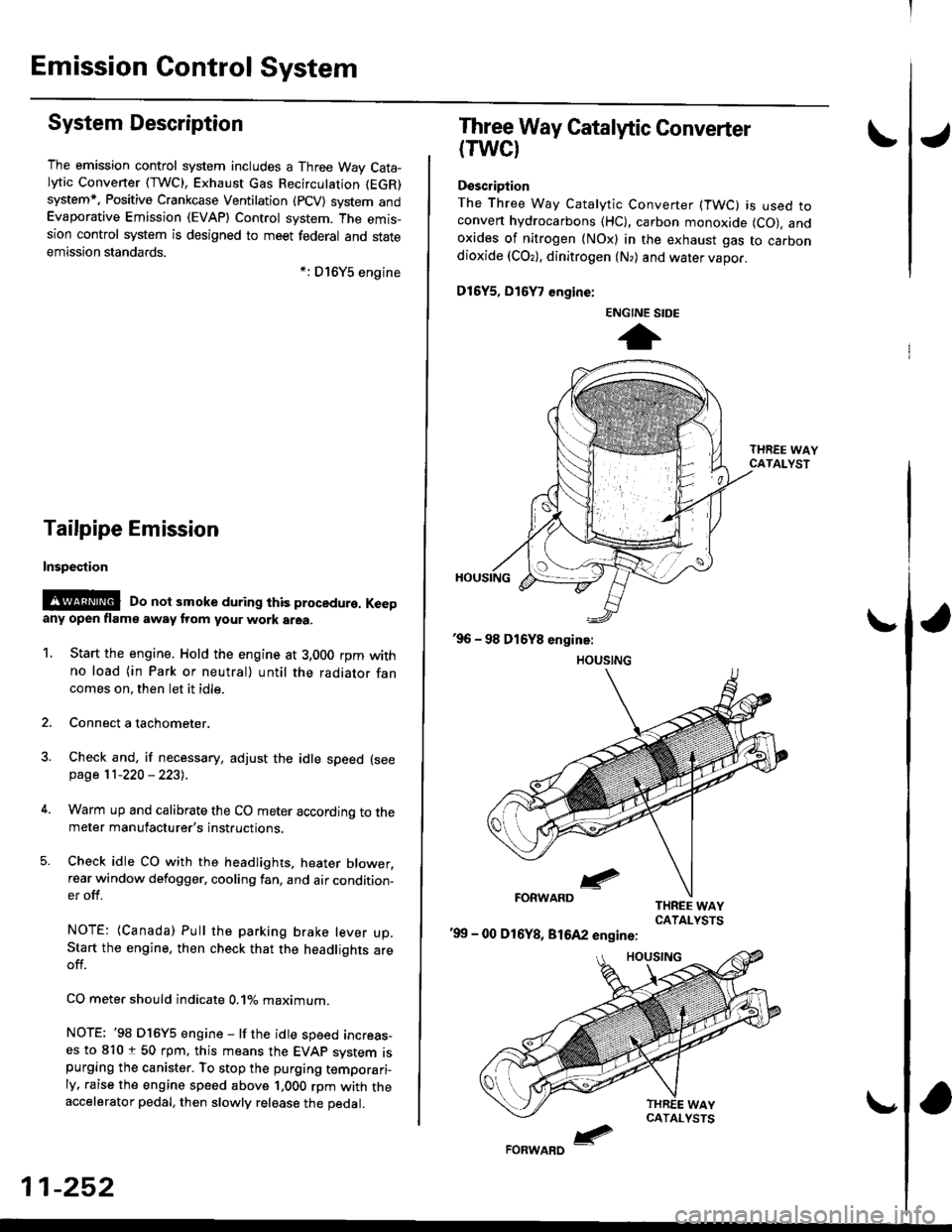
Three Way Catalytic Converter
(TWCI
Doscription
The Three Way Catalytic Converter (TWC) is used toconven hydrocarbons (HC), carbon monoxide (CO), andoxides of nitrogen (NOx) in the exhaust gas to carbondioxide (COr), dinitrogen (N,) and water vapor.
D15Y5, D16
, engine:
'99 - 00 D16Y8, 81642 engine:
ENGINE SIDE
t
Page 554 of 2189

\
\
(From page 11-284)
\(cont'd)
11-285
EVAP PURGE CONTROL SOI.INOID
VALVE 2P CONNECTOR IC114I
Wire side otfemaleterminals
?,
I,l,lil?"",,,u
EL,TWYEL)
Check the EVAP pirrge controlsolenoid valvei1. Disconnect the 2P connector
lrom the EVAP purge control
solenoid valve.
2. Ouickly raise the engine speed
to 3,000 rpm.
ls there vacuum?
InsDect vacuum ho56 routing.ll OK, replace the EVAP Purgecontrol solenoid valve.
Chock for a short in the wire(PCS linel:1. Turn the ignition switch OFF
2. Disconnect ECM/PCM connec'
tor A (32Pi.
3. Check for continuity between
the EVAP PUrge control sole
noid valve 2P connector termi
nal No.2 and body ground.
Check the vacuum when hot:
1. Turn the ignition switch OFF
2. Block the rear wheels and set
the parking brake.3. Jack up the front o{ the vehi-
cle and support it with safety
stands,4. Start the engine. Hold the
engine al 3,000 rpm wlth no
load (in Park or neutral) until
the radiator fan comes on, then
let it idle.5, Check for vacuum at the vac-
uum hose with transmissaonin gear (A/T in B Position,M/T in lst gear) after starting
the engrne.6. Ouickly raise the engine speed
to 3,000 rpm.
Reoair short in the wire botween
the EVAP purg€ cor|t]ol solenoid
valve and the ECM/pcM lA15l.ls there continuity?
Substitute a known-good ECM/
PCM and recheck. lf sYmPtom/indication goes eway. repl.c€ the
original ECM/PCM.
Check the EVAP Purg€ control
solenoid valve:1. Turn the ignition switch OFF
2. Disconnect the 2P connector
from the EVAP Purge control
solenoid valve and warm lt
up to normal operating tem_perature again if necessary
3. Stan the engine.4. At the harness side, measure
voltage between the EVAP
Purge control solenoid valve
2P connector terminal No. 1
and No. 2 with the transmission in gear (A,/T in E Posi-tion, M/T in 1st gear).
In3pect vacuum ho3€ touting.
ll OK, replace EVAP Purge con-
lrol aolenoid vtlv€.
Check lo. an open in the wire
llGl linel:At the harness side, measure volt
age between the EVAP Purge con-
trol solenoid valve 2P connectorterminal No. 1 and body groundRepeir open in tho wire between
EVAP purge conttol solenoid valv€
and the No. 15 ALTERNATOR SP
SENSOR (7.5 A fu3e
IBLK/YELI
lTo page 11 286i(To page 11-286)
Page 559 of 2189

Emission Control System
Ch€ck the EVAP purge controlsolenoid valv6:1. Disconnect the 2P connectorfrom the EVAP purge controlsolenoid valve.2. Ouickly raise the engine speedto 3,000 rpm.
Insped vacuum hose routing.lf OK. roplace the EVAP purge
control solonoid valve.
Chock tor r short in the wir€
{PCS line):1. Turn the ignition switch OFF.2. Disconnect ECM/PCM connec-tor A (32P).
3- Check tor continuity betweenthe EVAP purge control sole-noid valve 2P connector termi-nal No. 2 and body ground.
Check the vacuum when hot:1. Turn the ignition switch OFF.2. Block the rear wheels and setthe parking brake.3. Jack up the lront of the vehi-cle and support it with safetystands.4. Start the engine. Hold theengine at 3,000 rpm with noload (in Park or neutrali until
the radiator fan comes on, thenlet it idle.5. Check for vacuum at the vac-uum hose with transmissionin gear (A/T in E position,
lvl/T in 1st gear) after startingthe engine.6. Ouickly raise the engine speedto 3,000 rpm.
Rooair shoft in the wire belwegnthe EVAP pulg6 control solenoidvalvs and tho ECM/PCM {A61.ls there continuity?
Substitute a known-good ECM/PCM and rech6ck. lt 3ymptom/indicrtion 90e3 rway, r6plac6 th€o.iginal ECM/FCM.
Check th€ EVAP purge controlsolenoid valve:1. Turn the;gnition switch OFF.2. Disconnect the 2P connectorfrom the EVAP purge controlsolenoid valve and warm itup to normal operating tem-perature again if necessary.3. Start the engine.4- At the harness side, measurevoltage between the EVAPpurge control solenoid valve2P connector terminal No. 1and No.2 with the transmis-sion in gear {A/T in E posi-tion, M/T in lst geari.
In3pect vacuum hoae routing.lf OK, repl.ce EVAP purge con-trol solonoid valve.ls there battery voltage?
Chock for an open in the wire(lG1 lina):At the harnoss side, measure volt-age beNveen the EVAP purge con-trol solenoid valve 2P connectorterminal No. 1 and body ground.
Repair open in the wire b€lwe€nEVAP purge contrl 3olenoid valv6and lhe No. 15 ALTERNATOR SPSENSOR 17.5 A, fu3e.
ls there battery voltage?
Evaporative Emission (EVAPI Controls (cont'dl
(From page 11-289)
(To page 11-291)
11-290
IJ
EVAP PURGE CONTROL SOLENOIDVALVE 2P CONNECTOR IC114I
PCS
IRED/YEL)
temaletermrnars
of
PCS(RED/YEL)
tGlIBLK/YEL)
{To page 11 291)
Page 1229 of 2189
ABS Control Unit
Pulsers/Wheel
Sensors
Replacement
1. Remove the right side kick panel.
2. Disconnect the ABS control unit connecrors.
3. Remove the ABS control unit,
4. lnstall the ABS control unit in the reverse order of
removal,
CONNECTORS
19-76
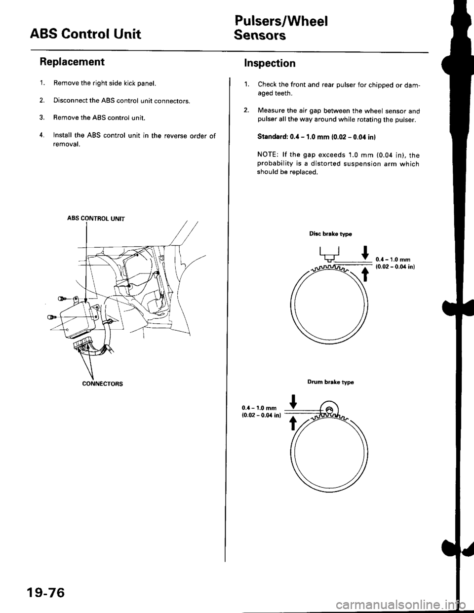
Inspection
Check the front and rear pulser for chipped or dam-aged teeth.
Measure the air gap between the wheel sensor andpulser all the way around while rotating the pulser.
Slandard: 0.4 - 1.0 mm (0.02 - 0.04 in,
NOTE; lf the gap exceeds 1.0 mm (0.04 in), theprobability is a distorted suspension arm which
should be replaced.
Dbc brake typo
0.{ - 1.0 mm(0.02 - 0.04 in)
Drum brake typ6
1.
Page 1684 of 2189
Wipers/Washers
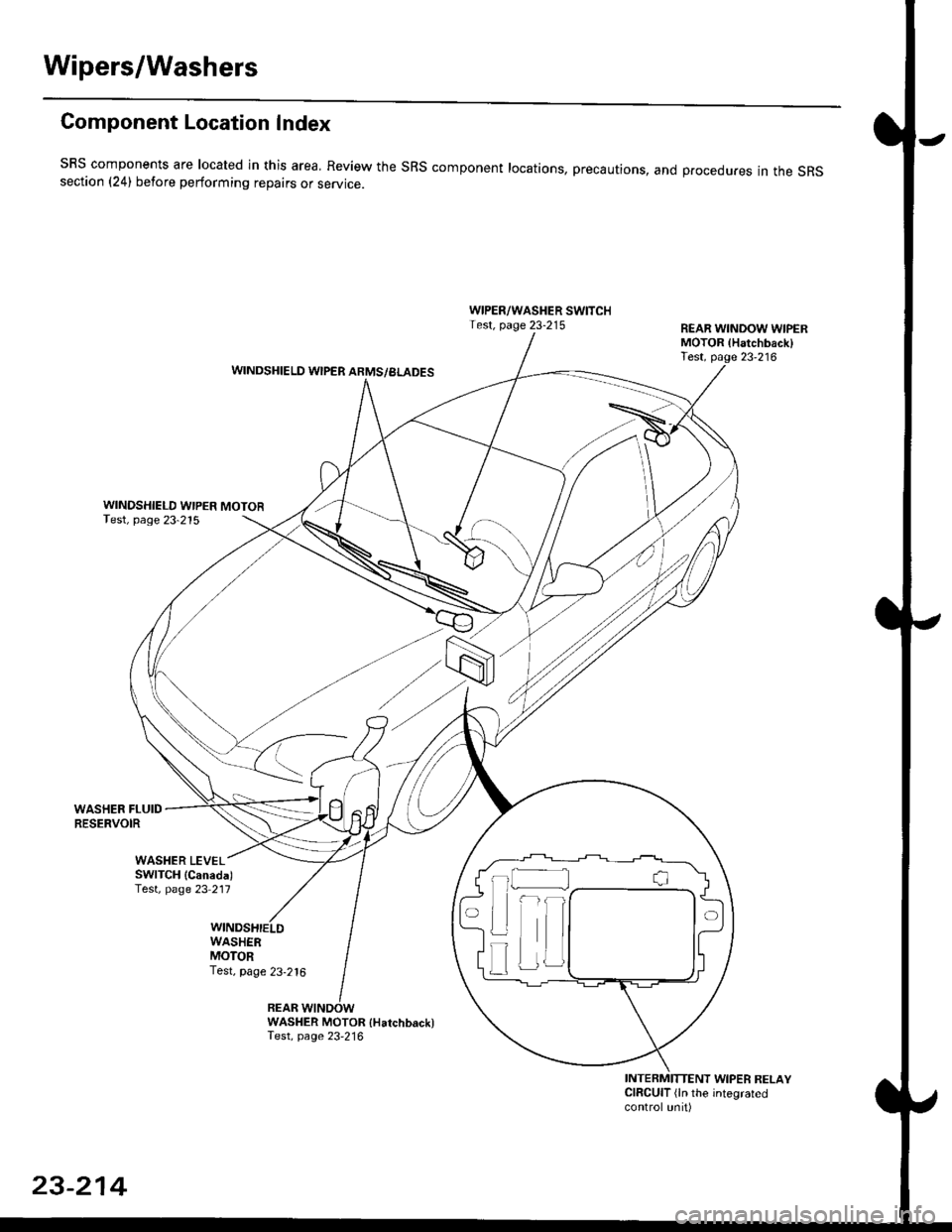
Component Location Index
SBS components are located in this area, Review the SRS component locations, precautions, and procedures in the SRSsection (241 betore performing repairs or service.
WIPER/WASHER SWITCHTest, page 23-215REAR WINDOW WIPERMOTOR lHatchback)Test, page 23'216WINDSHIELD WIPER ARMS/BLADES
WINDSHIELD WIPER MOTORTest, page 23-215
WASHER FLUIDRESERVOIR
WASHER MOTOR {Hatchback)Test, page 23'216
INTERMITTENT WIPER RELAYCIRCUIT (ln the integratedcontrol unit)
t_l
Iilr
i
T
23-214
Page 1697 of 2189
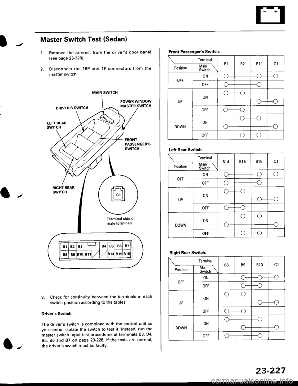
Master Switch Test (Sedan)
1.Remove the armrest from the driver's door panel
(see page 23-228).
Disconnect the 16P and 1P connectors from the
master switch.
Check for continuity between the terminals in each
switch position according to the tables
Driv€r's Switch:
The driver's switch is combined with the control unit so
you cannot isolate the switch to test it. Instead, run the
master switch input test procedures at terminals 83, 84,
85. BO and 87 on page 23-22A. lt the tests are normal,
the driver's switch must be faulty.
MAIN SWITCH
rFl
ll"'llt.:::::::l
B1B3B4B5B6B7
B889810811/l/leuBl5816
Terminalside of
male terminals
Front Passenger's Switch:
Terminal
P*,j--f$t,l"\B182811cl
OFFONCF--o
OFFooo
UPONo---o
o---o
OFFc\---o
DOWNON
o
oo
-o
OFFoo
Left Rear Swhch:
Terminal
P".r,-'-f-mn\814815816c1
OFFONG--o
OFFoo
UPONo--oo
o---o
OFFo-o
DOWNON
o-
o--o
o
OFFo--_o
Right Rear Switch:
Terminal
'**-T-*mB889B'�t0c1
OFFONo-o'o
OFFo---o
UPONo---o
CF--o
OFFCr---o
DOWNONo---.o
--oo-
OFFo---o
23-227
Page 2055 of 2189
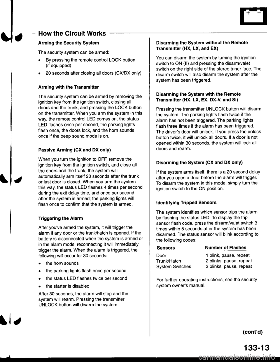
How the Circuit Works
Arming the Security System
The security system can be armed:
r By pressing the remote control LOCK button
(if equipped)
. 20 seconds atter closing all doors (C)UDX only)
Arming with the Transmitter
The security system can be armed by removing the
ignition key from the ignition switch, closing all
doors and the trunk, and pressing the LOCK button
on the transmitter. When you arm the system in this
way, the remote control LED comes on, the status
LED flashes once per second, the parking lights
flash once. the doors lock. and the horn sounds
once if the beeo sound mode is on.
Passive Arming (CX and Dx only)
When you turn the ignition to OFF, remove the
ignition key from the ignition switch, and close all
the doors and the trunk; the system will
automatically arm itself 20 seconds after the trunk
or last door is closed. When you arm the system
this way, the status LED tlashes 4 times per second
during the exit delay time, and once per second
after the system is armed; the parking lights will
flash once to confirm that the system is armed.
Triggering the Alarm
Atter you've armed the system, it will trigger the
alarm if any door or the trunldhatch is opened. lf the
battery is disconnected when the system is armed or
in the alarm mode, reconnecting it will immediately
trigger the alarm. When the alarm is triggered, the
following will occur for 30 seconds:
. the horn sounds
o the parking lights flash once per second
. the status LED flashes hvice oer second
. the starter is disabled
After 30 seconds, the alarm will stop and the
system will rearm. Pressing the transmitter
UNLOCK button will disarm the svstem.
tlr
133-13
Disarming the System without the Remote
Transmitter (HX, LX, and EX)
You can disarm the system by turning the ignition
switch to ON (ll) and pressing the disarm/valet
switch on the right side ol the stereo tuner face. The
disarm switch will also disarm the svstem after the
system has been triggered.
Disarming the System with the Remote
Transmitter (Hx, Lx, Ex, DX-V, and Si)
Pressing the transmitter UNLOCK button will disarm
the system. The parking lights llash t\ivice if the
alarm has not been tnggered. The parking lights
flash three times if the alarm has been triggered.
The driver's door will unlock. lf you press the unlock
button twice, it will unlock all doors. lf a door is not
opened within 30 seconds, the system will lock all
doors and rearm.
Disarming the System (CX and DX only)
lf the system arms itself, there is a 20 second delay
after you open a door before the alarm will trigger.
To disarm the system in this mode, simply turn the
ignition switch to the ON position
ldentitying Tripped Sensors
The system identifies which sensor trips the alarm
by flashing the status LED. To display the trip
sensor flash code, press the disarm/valet switch 3
times within 5 seconds after the system has been
disarmed. The status sensor will blink according to
the followino codes:
SensorsNumber of Flashes
Door
TrunldHatch
System Switches
1 blink, pause, repeat
2 blinks, pause, repeat
3 blinks, pause, repeat
For further operating instructions, see the security
syslem owner's manual.
(cont'd)
Page 2117 of 2189
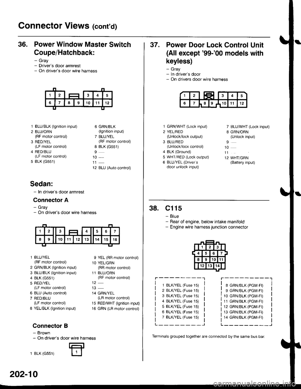
Connector Views (cont'd)
36. Power Window Master Switch
Coupe/Hatchback:
- Gray- Driver's door armrest- On driver's door wire harness
3
5
BLU/BLK (lgnition input)
BLU/ORN(RF motor control)
RED/YEL(LF motor control)
FED/BLU(LF motor control)
BLK (G551)
6 GRN/BLK(lgnition input)
7 BLU/YEL(RF motor control)
8 BLK (G551)
10
12 BLU (Auto control)
I YEL (RR motor control)
1O YEUGRN(RR motor control)
11 BLU/ORN(RF motor control)
14 GRN/YEL(LR motor control)
15 REDMHT (lgnition input)
16 GRN (LR motor control)
Sedan:
- In driver's door armrest
Connector A
- Gray- On driver's door wire harness
l BLU/YEL(RF motor control)
2 GRN/BLK (lgnition input)
3 BLU/BLK (lgnition input)
4 BLK (G551)
5 RED/YEL(LF motor control)
6 8LU (Auto control)
7 RED/BLU(LF motor control)
8 YEUBLK (lgnition input)
Connector B
- Brown- On driver's
1 BLK (Gss1)
door wire harness
E
202-10
Terminals grouped together are connected by the same bus bar
37. Power Door Lock Control Unit
(All except'99-'00 models with
keyless)
- Gray- In driver's door- On drivers door wire harness
1 GRNMHT (Lock input)
2 YEURED(Unlock/lock output)
3 BLU/RED(unlock/lock control)
4 BLK {Ground)5 WHT/RED (Lock output)
6 BLU/YEL (Drivefs
door unlock input)
7 BLU/WHT (Lock input)
B GRN/ORN(Unlock input)
10
11
12 WHT/GRN(Battery input)
38. Cl15
- Blue- Rear of engine, below intake manifold- Engine wire harness junction connector
r----------lr---------"1
1 8LK?ryEL (Fuse 15)
2 BLK/YEL (Fuse 15)
3 BLK TEL (Fuse 15)
4 BLK/YEL (Fuse 15)
5 BLK,/YEL (Fuse 15)
6 BLK/YEL (Fuse 15)
7 BLK,TYEL (Fuse 15)
8 GRN/8LK (PGM FD
9 GRN/BLK (PGM.FD
10 GRN/BLK (PGr\,4-Fr)
11 GBN/BLK (PGM-Fr)
12 GRN/BLK (PGM-FD
13 GRN/BLK (PGM-FD
14 GRN/BLK (PGM-Fr)
L_______-JL______--_J