Page 262 of 2189
tl
Engine Coolant Refilling and Bleeding
CAUTION: when pouring engine coolant, be sure to
shut the relay box lid and not to lst coolant spill on the
eleqtrical parts or the paint. lf any coolant spills, rinse it
off immediately.
1. Slide the heater temperature control lever to maxl-
mum heat. Make sure the engine and radiator are
cool to the touch.
Remove the radiator caP.
Loosen the drain plug, and drain the coolant'
Remove the drain bolt from the cylinder block'
D16Y5. D16Y7, Dl6Yg sngines:
DRAIN PLUG
0d
I ro
78 N.m {8.0 kgl m.58lbt'ft)
6.
1.
B1642 engin€:
WASHERReplace.
DRAIN BOLT78 N m (8 0 kgf m' 58lbfft)
Apply liquid gasket to the drain bolt threads, then
reinstall the bolt with a new washer and tighten 't
securely.
Tighten the radiator drain plug securely
Remove, drain and reinstall the reservoir' Fill the
tank halfway to the MAX mark with water, then up
to the MAX mark with antitreeze.
(cont'd)
10-7
MAX MARK
Page 1174 of 2189
Front Brake Caliper
Reassembly (cont'dl
7.Apply the recommended seal grease in the caliperseal set to the sliding surface of sleeve A and theinside of a new guide pin boot.
Install the guide pin boot into the groove in thesleeve A.
Make sure that the brake pad retainers and brakepads are in their original positions (see page 19-10).
Install the caliper onto sleeve A, and pivot it downinto position.
NOTE: Install the guide pin boot into the groove inthe caliper properly.
BRACKET
SLEEVE A
19-20
11.Connect the brake hose to the caliper with new seal-ing washers, and tighten the banjo bolt.
Tighten the caliper bolt B.
Fill the brake reservoir and bleed the brake svstem(see page 19-7).
Perform the following checks.. Check for leaks at hose and line ioints and con-nectaons, and retighten if necessary.. Check for brake hoses for interference and twist-Ing.
13.
14.
BANJO BOLT
26 N.m (2.7 kgl.m, 20 lbtftl
Page 1175 of 2189

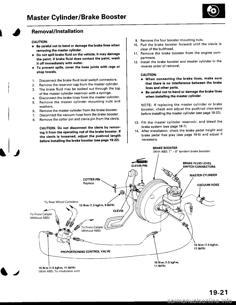
Master Cylinder/Brake Booster
IRemovaUlnstallation
CAUTION:
. Be care{ul nol to bend or damage the brake lines when
rsmoving the mastsr cYlinder.
. Do not soill brakefluid on the vehicle; it may damage
the paint; if brake fluid does contact the paint, wssh
it off immediatelY with water'
. To prevent spill3, cover the hose ioints with rags or
shop towels.
9. Remove the four booster mountlng nuts
10. Pull the brake booster forward until the clevis is
clear of the bulkhead.
11. Remove the brake booster from the engine com-
panmenr.'12. Install the brake booster and master cylinder in the
reverse order of removal.
CAUTION:
. When connecting the brake lines. make sure
that there is no inte erence between the brake
lines and oth6r Parts.
r Be careful not to bend or damage the brake lines
when installing the master cylinder.
NOTE: lf replacing the master cylinder or brake
booster, check and adiust the pushrod clearance
be{ore installing the master cylinder (see page 19-221'
Fill the master cylinder reservoir, and bleed the
brake svstem (see Page 19-7).
After installation. check the brake pedal height and
brake pedal tree play (see page l9-5) and adjust if
necessary.
BRAKE BOOSTER(With ABS: 7" + 8" tandem brake booster)
BRAKE FLUIO LEVELSWITCH CONNECTORS
MASTER CYLINDER
VACUUM HOSE
1.
2.
3,
5.
Disconnect the brake fluid level switch connectors'
Remove the reservoir cap from the master cylinder'
The brake fluid may be sucked out through the top
of the master cylinder reservoir with a syrlnge.
Disconnect the brake lines from the master cylinder'
Remove the master cylinder mounting nuts and
washers.
\l/
6. Remove the master cylinder from the brake booster'
7. Disconnect the vacuum hose trom the brake booster'
8. Remove the cotter pin and clevis pin from the clevis'
CAUTION: Do not disconnect the clevb by remov-
ing it from the operating rod of the brako booster' lf
the clevis is loosened, adiust the pushrod length
before installing th€ brake booster (see page 19-221'
COTTER PINReplace.
To Rear Wheel Cylinders
14.
-6.4CLEVIS PIN
To Front Caliper(Without ABS)$
t'N't'ttrnt'-''
To Front CaliperlWithout ABSi
PBOPORTIONING CONTROL VALVE
15 N.m {1.5 kgl m,11 tbtft)
15 N.m {1.5 kgif.m, 11 lbtft}(With ABS: To modulator unit)lr
19-21
Page 1188 of 2189

Rear Brake Caliper
Reassembly (cont'dl
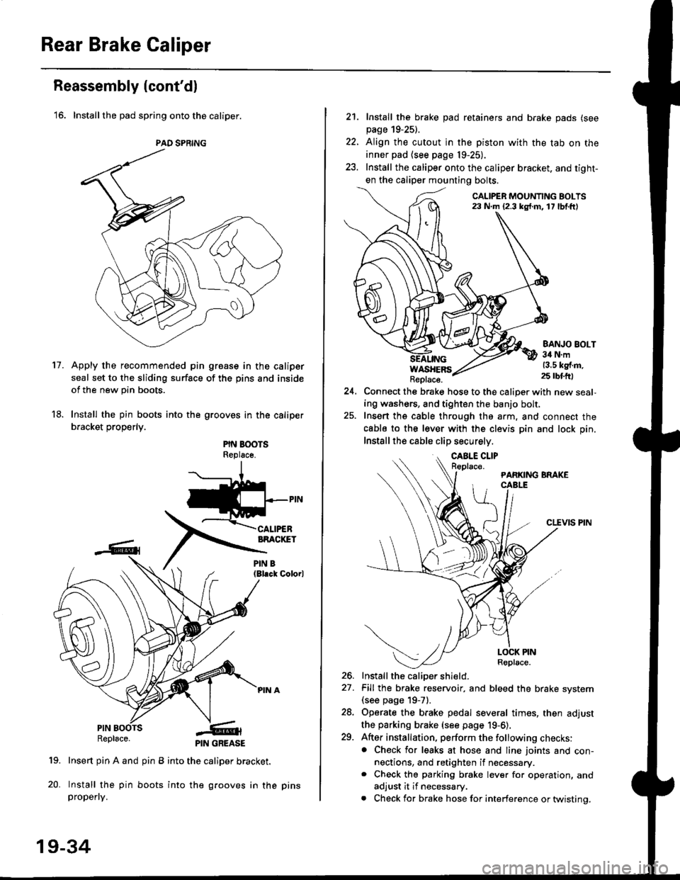
'16. Installthe pad spring onto the caliper.
Apply the recommended pin groase in the caliper
seal set to the sliding surface of the pins and inside
of the new pin boots.
Install the pin boots into the grooves in the caliper
bracket properly.
PIN BOOTSReplsce.
(Bl.ck Colorl
PINRepl6ce.
19. Insert pin A and pin B into the caliper bracket.
20. Install the pin boots into the grooves in thepropefly.
PAD SPRING
11.
PIN GREASE
19-34
pr ns
22.
21. Install the brake pad retainers and brake pads (see
page 19-25).
Align the cutout in the piston with the tab on the
inner pad (see page 19-25).
Install the caliper onto the caliper bracket. and tight-
en the caliper mounting bolts.
CALIPER MOUNTING BOLTS23 N.m {2.3 kg{.m. 17 lbf.ft)
WASHERSReplace.
BANJO BOLT34 N.m13.5 kg{.m.25 rbtft)
24.Connect the brake hose to the caliper with new seal,
ing washers, and tighten the banjo bolt,
Insert ths cable through the arm, and connect the
cabls to the lever with the clevis pin and lock pin.
Install the cable clip securely.
CLEVIS PIN
-t
//t
LOCK PINRoplace.
26. Install the caliDer shield.
27. Fill the brake reservoir, and bleed the brake svstem(see page 19-71.
28. Operate the brake pedal several times, then adjust
the parking brake (see page 19-6).
29. After installation, perform the following checks:. Check for leaks at hose and line joints and con-nections, and retighten if necessary.. Check the parking brake lever for operation, and
adjust it if necessary.
. Check for brake hose for interference or twistinq.
Page 1337 of 2189
Opener Cable/Opener and Latch/Wiper and Washer
Component Location Index
2Dt3DItD'
y"Tl,"nll,ib?*'r.* o*t"
Replacement, Page 20_1 13
Adiustment, Page 20'1 17
WINDSHIELDWASHER NOZZLESAdjustment, Page 20_1 17
HOOD LATCH
{see page 20-110)
REAR WINDOW WIPER
ARM and MOTORReplacement, Page 20-1 15
Adjustment, page 20 117
LOCK CYLINDER(see page 20 113)
LOCK CYLINDER
TRUNK LIO LATCH
{see page 20 112)
FUEL LID OPENERCABLE(see page 20-108i
LID OPENERCABLE(see page 20 108)
LID/FUELLID OPENER(see page 20 111)
RELEASE HANDLE(see page 20-110)
3D:
REAR WINDOWWASHER NOZZLEAdiustment, page 20-1 17
REAR WINDOWWASHER TUBE(see page 20-116)
HATCH OPENERCABLE(see page 20 110)
WASHER RESERVOIRReplacement, Page 20-1 15
HATCH/FUEL LID OPENER(see page 20 1'11)
FUEL LID OPENERCABLE(see page 20 110)
(see page 20 111)
20-107
Page 1345 of 2189

Rear Window Wiper
Arm and MotorWasher Reservoir
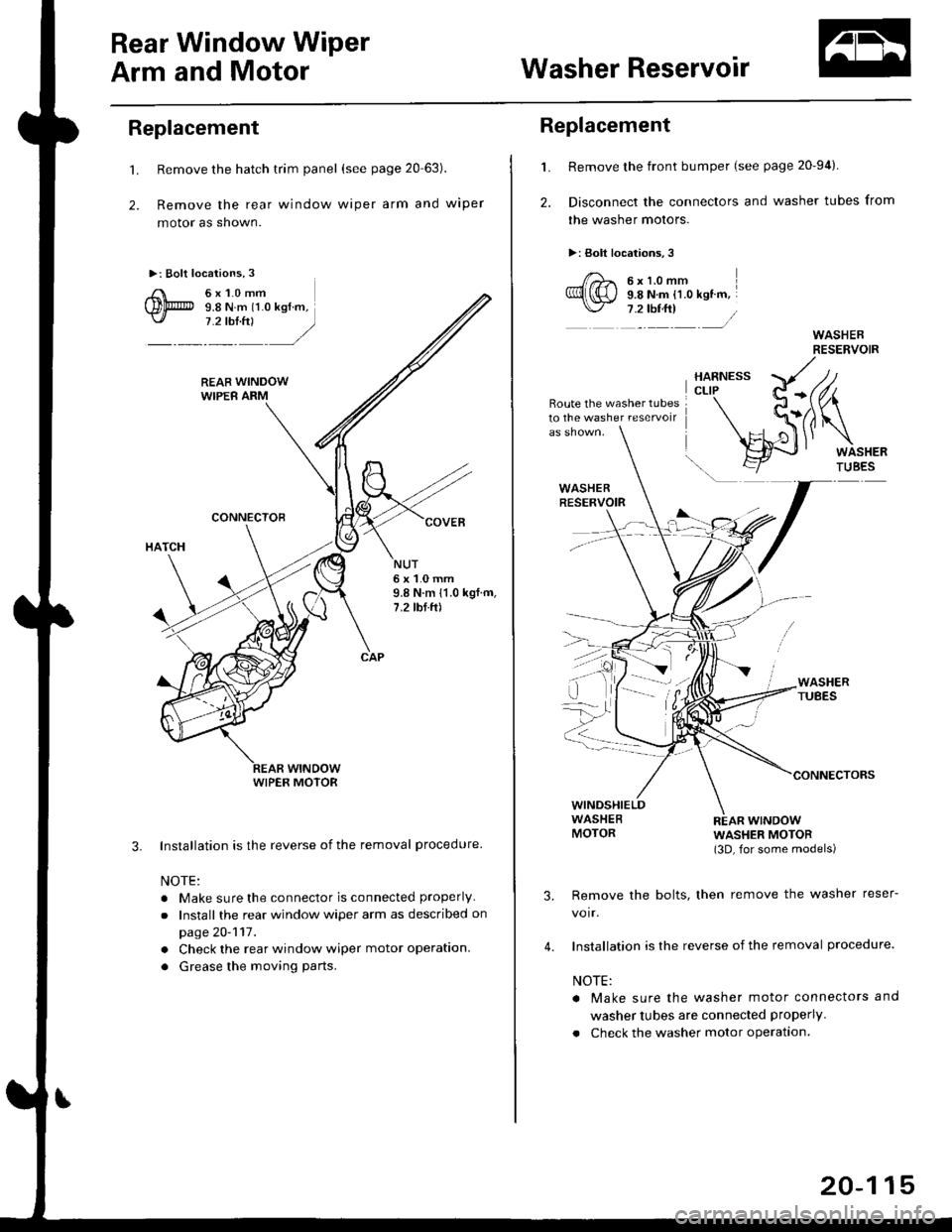
Replacement
't.
2.
Remove the hatch trim panel (see page 20 63).
Remove the rear window wiper arm and wiper
motor as shown.
Installation is the reverse of the removal procedure
NOTE:
. Make sure the connector is connected properly
.Install the rear window wiper arm as described on
page 20-117.
. Check the rear window wiper motor operation.
. Grease the moving parts.
3.
NUT6x1.0mm9.8 N.m 11.0 kgf.m,7.2 tbf.ft)
WIPER MOTOR
L
2.
Replacement
Remove the front bumper (see page 20-94).
Disconnect the connectors and washer tubes from
the washer motors.
>: Bolt locations,3
/)^ 6xt.omm
Ql(S) s.e ru.- tt.o ret '".\./ 7 .2 tbf.ft) /
Route the washer tubes10 the washe. reservoir
wtNDowWASHER MOTOR(3D, for some models)
Remove the bolts, then remove the washer reser-
voir.
Installation is the reverse of the removal procedure.
NOTE:
a Make sure the washer motor connectors and
washer tubes are connected properly.
. Check the washer motor operation.
3.
4.
20-115
Page 1346 of 2189

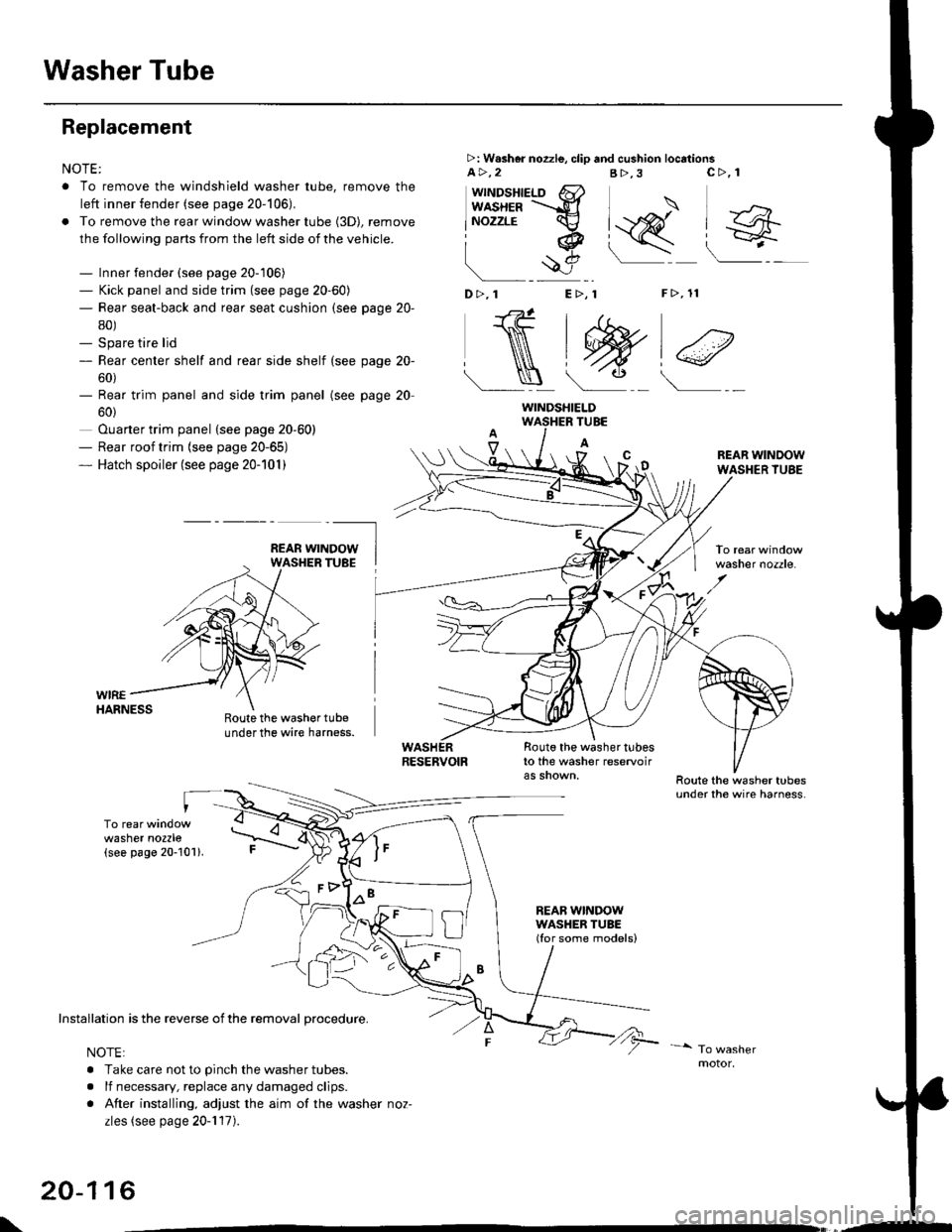
Washer Tube
Replacement
NOTE:
. To remove the windshield washer tube, remove the
left inner fender (see page 20-106),
. To remove the rear window washer tube {3D), remove
the following parts from the left side of the vehicle.
- Inner fender (see page 20-106)- Kick panel and side trim (see page 20-60)- Rear seat-back and rear seat cushion (see page 20-
80)- Spare tire lid- Rear center shelf and rear side shelf (see page 20-
60)- Rear trim panel and side trim panel
60)
Ouarter trim panel (see page 20-60)- Rear roof trim {see page 20-65)- Hatch spoiler (see page 20-101)
(see page 20
WIREHARNESS
>: W.sher nozzle, clip and cushion locationsa>,2B>,3
"J>)
[q@"
F>, 11
c>, 1
wttrtosnteLo 6}usxea =-d
lNozzrE cv
iq
!$e
D>,1 E>, 1
NtW)€
Roote the washer tubeunder the wire harness.
TUBE
A
Route the washer tubesto the washer reservoir
REAB WINDOWWASHER TUBE(Ior some models)
REAR WINDOWWASHER TUBE
washer nozzle.
washer nozzle(see page 20-101).
oo\
Installation is the reverse of the removal procedure.
NOTE:
. Take care not to pinch the washer tubes.
. lf necessary, replace any damaged clips.
. After installing, adjust the aim of the washer noz-
zles (see page 20-117).
20-116
WINDSHIELD
\,--
Page 1358 of 2189
Washer Tube
Replacement
NOTE: To remove the windshield washer tube,
>: Washar nozzle, clip and cushion locations
a>,2B>, 1
remove the left inner fender (see page 20-106).
c>, 1 D>,'tE>, 1F>, 1 G>, 1
n,i#,T
l_<.l_N.j w)*)lW)e)
I
9)
ECM/PCMBRACKET
WIREHARNESS
WINOSHIELDTUBE
A
Route the washer tubeunder the wire harnessRoute the washer tube
behind the EcM/PcM bracket.
(cont'd)
RESERVOIR
\/
Route the washer tubesto the washer reservolrRoute the washer tubes
under the wire harness.
Installation is the reverse of the removal procedure.
NOTE:
. Take care not to Dinch the washer tubes.
. lf necessary, replace any damaged clips.
. After installing, adjust the aim of the washer nozzles (see page 20-117l'
c-------.-
REAR WINDOWWASHER TUBE
20-129