Page 1729 of 2189

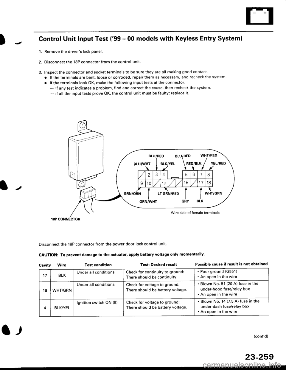
)Control Unit Input Test ('99 - 00 models with Keyless Entry System)
1.Remove the driver's kick panel.
Disconnect the 18P connector from the control unit.
Inspect the connector and socket terminals to be sure they are all making good contacl.
. lf the terminals are bent, loose or corroded, repair them as necessary, and recheck the system
. lf the terminals look OK, make rhe following input tests at the connector.
- lf anv test indicates a problem, find and correct the cause, then recheck ihe system
- lf all the input tests prove OK, the control unit must be faulty; replace it
Wire side oI female terminals
Disconnect the 18P connector from the power door lock control unit.
CAUTION: To provent damage to the actuator, apply battery Yoltage only momentarily.
Cavity Wir€ Test conditionTest: Desired resultPossible cause if result is not obtained
BLK/YELRED/SLK
25618
910/,'2 ,/
'151718
LTWHT
17BLKUnder all conditionsCheck for contlnuity to ground:
There should be continuity.
. Poor ground (G551)
. An open in the wire
t8WHT/GRN
Under all conditionsCheck tor voltage to ground:
There should be battery voltage.
. Blown No. 5'1 (20 A) luse in the
under-hood tuse/relay box
. An open in the wire
4B LK/YEL
lgnition switch ON (ll)check for voltage to ground:
There should be battery voltage.
Blown No. l4 (7.5 A) fuse in the
under-dash fuse/relay box
An open in the wire
(cont'd)
23-259
l-r
Page 1824 of 2189

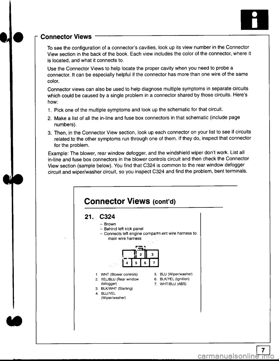
Connector Views
To see the configuration of a connector's cavities, look up its view number in the Connector
View section in the back of the book. Each view includes the color of the connector, where it
is located, and what it connects to.
Use the Connector Views to help locate the proper cavity when you need to probe a
connector. lt can be especially helpful if the connector has more than one wire of the same
cotor.
Connector views can also be used to help diagnose multiple symptoms in separate circuits
which could be caused by a single problem in a connector shared by those circuits. Here's
how:
1. Pick one of the multiple symptoms and look up the schematic for that circuit.
2. Make a list of all the in-line and fuse box connectors in that schematic (include page
numbers).
3. Then, in the Connector View section, look up each connector on your list to see il circuits
related to the other symptoms run through one of them. lf they do, inspect that connector
for the oroblem.
Example: The blower, rear window defogger, and the windshield wiper don't work. List all
in-line and fuse box connectors in the blower controls circuit and then check the Connector
View section (sample below). You find that C324 is common to the rear window defogger
circuit and wiper/washer circuit, so you inspect C324 and find the problem, bent terminals.
5.
6.
7.
1.
2.
WHT (Blower controls)
YEUBLU (Rear window
defogger)
BLK,ryVHT (Starting)
BLU/YEL(Wiper/washe0
8LU (Wiper/washed
BLfiEL (lgnition)
WHT/BLU (ABS)
Connector Views (cont'd)
21. C324
Brown
Behind left kick panel- Connects left engine compartry'ent wire harness to
main wire harness
ll,ll,
567
Page 2090 of 2189
55. Behind Left Side of Dash Panel58. Behind Left Side of Dash Panel
c712(3-BRN) ('96 Model)(3-GRN) ('97-'00 Models)
56. Upper Left Kick Panel59. Behind Left Side of Dash Panel
57. Left Kick Panel Area60. Behind Left Side of Dash Panel
201 -9
Page 2095 of 2189
Cornponent Location
85. Behind Right Kick Panel\
\
88. Driver's Door
CONNECTOR B ii
86. Behind Right Kick Panel89. Top Front of Driver's Door (Frt. Pass. Similar)
87. Underside of Driver's Seat90. Front of Driver's Door (Frt. Pass. Similar)
201-14
\
Page 2101 of 2189
Gomponent Location
121. Behind Left Kick Panel ('96-'98 CVT)\124. Rear of Engine Compartment (CVT)
TRANSMISSIONCONTROL MODULE(rcM)
122. Right Side Lower Engine Compartment (CVT)125. Behind Right Side of Dash Panel
\
123. Right Front of Engine (CVT)126. Underside of Hatch Lid
k
2A1-20
\
Page 2103 of 2189
Component Location
133. Below Rear of D16Y8 Eng. (816A2 Similar) ('99-'00)
I
\
\
136. Behind Left Side of Front Console ('99-'00)
134. Behind Kick Panel ('99-'00)137. Behind Center Panel ('99-'00)
135" Behind Left Side of Dash Panel ('99-'00)138. Behind Front Console
c723(20-GRY) ('96-'98 Models)(24-BLU) ('99-'00 Models)
201-22
t,![!!til**}t$]Sl1Ht€:!i!ifj*#
Page 2104 of 2189
139. Behind Glove Box ('99-'00)142. Lett Rear Corner Engine Gompartment (GX)
140. Underside of Rear Shelf ('99-'00 Sedans)143. Right Rear of Engine Compartment (GX)
141. Top Center of Engine (GX)144. Behind Left Kick Panel (GX)
201-23
Page 2109 of 2189

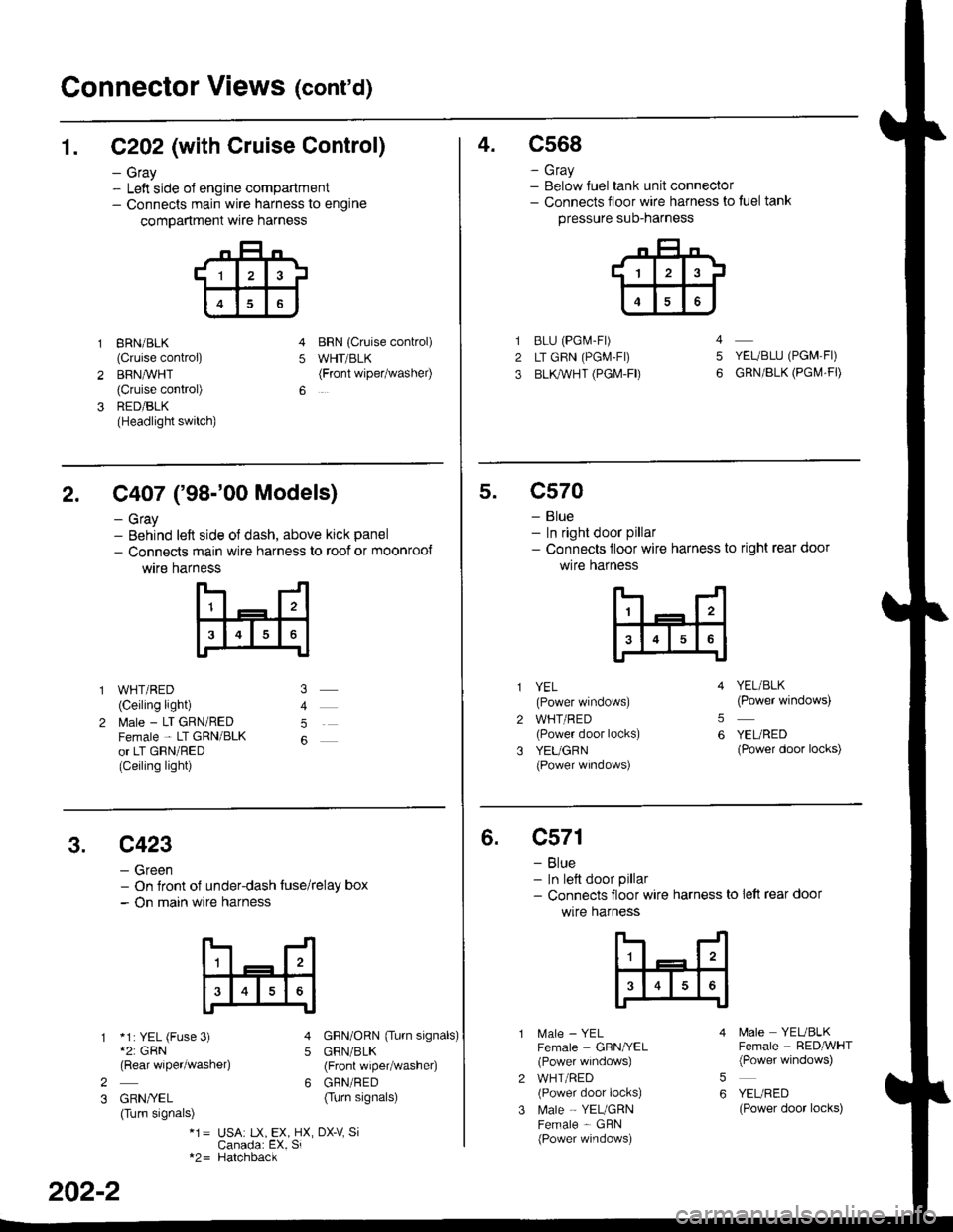
Connector Views (cont'd)
1. C202 (with Cruise Control)
- Gray- Left side ol engine compartment- Connects main wire harness to engine
compartment wre harness
gRN/BLK
(Cruise control)
BRN,ryVHT(Cruise control)
RED/BLK(Headlight switch)
BRN {Cruise conkol)
WHT/BLK(Front wipetwashel)5
4.c568
- Gray- Below Juel tank unit connector- Connects floor wire harness to tuel tank
pressure suo-narness
BLU (PGi.4-Fr)
LT GRN (PGM-FI)
BLl(WHT (PGI\4-FD
YEUBLU (PGM,FI)
GRN/BLK (PGI\,4.FD
4
5
2. C407 ('98-'00 Models)
- Gray- Behind left side ol dash, above kick panel
- Connects main wire harness to roof or moonroo{
wtre harness
WHT/RED(Ceiling light)
l\4ale - LT GRN/REDFemale - LT GRN/BLKor LT GRN/RED(Ceiling light)
5
5.c570
- Blue- In right door pillar- Connects floor wire harness to right rear door
wlre hafness
2
3
YEL(Power windows)
WHT/RED(Power door locks)
YEUGRN(Power wrndows)
YEL/BLK(Power windows)
YEURED(Power door locks)
5
6
3.c423
- Green- On Jront of under-dash tuse/relay box- On main wire harness
*1: YEL (Fuse 3)*2: GRN(Rear wiper/washe4
GRN/YEL(Turn signals)
GRN/ORN {Tu.n signals)
GRN/BLK(Front wiper/washer)
GRN/RED(Turn signals)
5
62
3
*1= USA: tX, EX, HX, DX-V SiCanada: EX, Si*2= Hatchback
202-2
6.c571
- Blue- In lett door pillar- Connects floor wire harness to lett rear door
wlre harness
MaIe _ YELFemale - GBN/YEL(Power windows)
WHT/RED(Power door locks)
Male - YEUGRNFemale - GBN(Power windows)
5
6
N4ale YEUBLKFemale - RED,ryVHT(Power windows)
YEURED(Power door locks)