Page 1 of 26
26-41
Secondary air system Secondary air system,
function/components
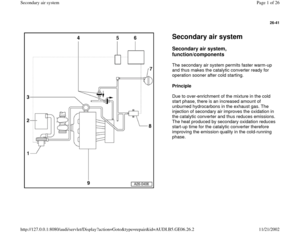
The secondary air system permits faster warm-up
and thus makes the catalytic converter ready for
operation sooner after cold starting.
Principle
Due to over-enrichment of the mixture in the cold
start phase, there is an increased amount of
unburned hydrocarbons in the exhaust gas. The
injection of secondary air improves the oxidation in
the catalytic converter and thus reduces emissions.
The heat produced by secondary oxidation reduces
start-up time for the catalytic converter therefore
improving the emission quality in the cold-running
phase.
Pa
ge 1 of 26 Secondar
y air s
ystem
11/21/2002 htt
p://127.0.0.1:8080/audi/servlet/Dis
play?action=Goto&t
yp
e=re
pair&id=AUDI.B5.GE06.26.2
Page 2 of 26
26-42
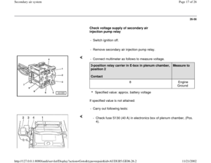
Function
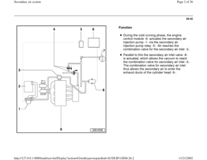
During the cold running phase, the engine
control module -6- actuates the secondary air
injection pump -1- via the secondary air
injection pump relay -5-. Air reaches the
combination valve for the secondary air inlet -3-.
Parallel to this the secondary air inlet valve -8-
is actuated, which allows the vacuum to reach
the combination valve for secondary air inlet -3-.
The combination valve for secondary air inlet
thus allows the secondary air to enter the
exhaust ducts of the cylinder head -9-.
Pa
ge 2 of 26 Secondar
y air s
ystem
11/21/2002 htt
p://127.0.0.1:8080/audi/servlet/Dis
play?action=Goto&t
yp
e=re
pair&id=AUDI.B5.GE06.26.2
Page 3 of 26
26-43
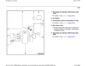
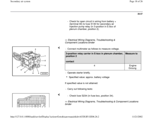
1 -
Secondary Air Injection (AIR) Pump motor
-V101-
Location Fig. 2
, Page 26
-45
2 -
Air cleaner
3 -
Combination valve for secondary air inlet
Location Fig. 4
, Page 26
-46
4 -
Non-return valve
Position (light side/ dark side or direction of
arrow) as shown in illustration, arrow faces
in direction of flow
5 -
Secondary Air Injection (AIR) Pump relay -
J299- Location Fig. 3
, Page 26
-46Pa
ge 3 of 26 Secondar
y air s
ystem
11/21/2002 htt
p://127.0.0.1:8080/audi/servlet/Dis
play?action=Goto&t
yp
e=re
pair&id=AUDI.B5.GE06.26.2
Page 4 of 26
26-44
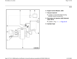
6 -
Engine Control Module -J220-
7 -
Vacuum reservoir
Location: In front left wheel housing
beneath wheel housing liner
8 -
Secondary Air Injection (AIR) Solenoid
valve -N112- Location Fig. 1
, Page 26
-45
9 -
Cylinder head
Pa
ge 4 of 26 Secondar
y air s
ystem
11/21/2002 htt
p://127.0.0.1:8080/audi/servlet/Dis
play?action=Goto&t
yp
e=re
pair&id=AUDI.B5.GE06.26.2
Page 5 of 26
26-45
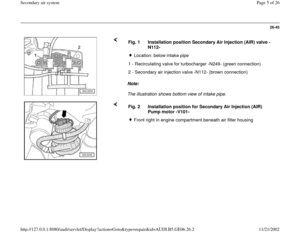
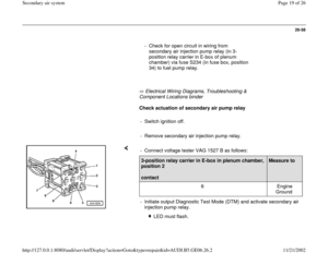
Note:
The illustration shows bottom view of intake pipe. Fig. 1 Installation position Secondary Air Injection (AIR) valve -
N112-
Location: below intake pipe
1 - Recirculating valve for turbocharger -N249- (green connection)
2 - Secondary air injection valve -N112- (brown connection)
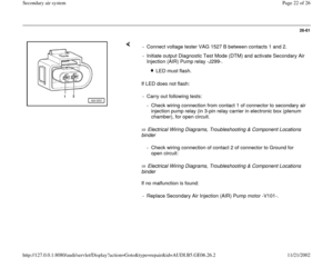
Fig. 2 Installation position for Secondary Air Injection (AIR)
Pump motor -V101-
Front right in engine compartment beneath air filter housing
Pa
ge 5 of 26 Secondar
y air s
ystem
11/21/2002 htt
p://127.0.0.1:8080/audi/servlet/Dis
play?action=Goto&t
yp
e=re
pair&id=AUDI.B5.GE06.26.2
Page 6 of 26
26-46
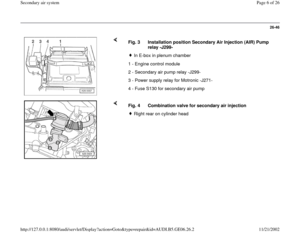
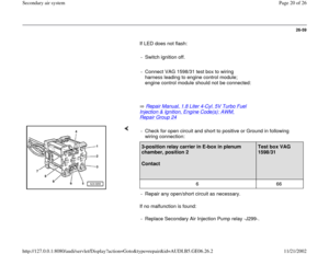
Fig. 3 Installation position Secondary Air Injection (AIR) Pump
relay -J299-
In E-box in plenum chamber
1 - Engine control module
2 - Secondary air pump relay -J299-
3 - Power supply relay for Motronic -J271-
4 - Fuse S130 for secondary air pump
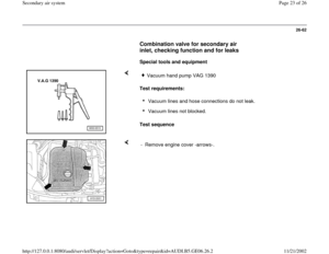
Fig. 4 Combination valve for secondary air injection
Right rear on cylinder head
Pa
ge 6 of 26 Secondar
y air s
ystem
11/21/2002 htt
p://127.0.0.1:8080/audi/servlet/Dis
play?action=Goto&t
yp
e=re
pair&id=AUDI.B5.GE06.26.2
Page 7 of 26
26-47
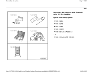
Secondary Air Injection (AIR) Solenoid
valve -N112-, checking
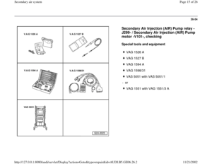
Special tools and equipment
VAG 1526 A
VAG 1527 B
VAG 1594 A
VAG 1598/31
VAS 5051 with VAS 5051/1
- or
VAG 1551 with VAG 1551/3 A
Pa
ge 7 of 26 Secondar
y air s
ystem
11/21/2002 htt
p://127.0.0.1:8080/audi/servlet/Dis
play?action=Goto&t
yp
e=re
pair&id=AUDI.B5.GE06.26.2
Page 8 of 26
26-48
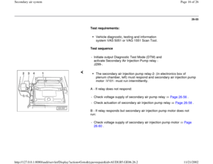
Test requirements:
Vehicle diagnostic, testing and information
system VAS 5051 or VAG 1551 Scan Tool
connected.
Test sequence
Note:
The secondary air injection solenoid valve -
N112- and the wiring connections are monitored
by the engine control module.
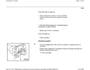
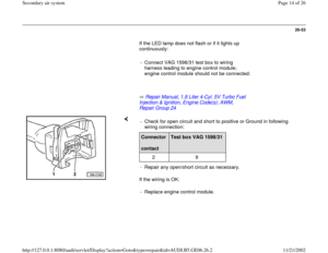
- Read out Diagnotic Trouble Code (DTC)
memory of engine control module.
If a DTC relating to the secondary air injection
solenoid valve -N112- is displayed:
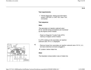
Note:
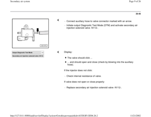
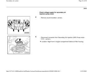
The illustration shows bottom view of intake line. - Remove hoses from secondary air injection solenoid valve -N112- (-2-)
but leave electrical connector plugged in.
Location: below intake line
Pa
ge 8 of 26 Secondar
y air s
ystem
11/21/2002 htt
p://127.0.0.1:8080/audi/servlet/Dis
play?action=Goto&t
yp
e=re
pair&id=AUDI.B5.GE06.26.2


 Pump motor
-V101-
Location Fig. 2
, Page 26
-45
2 -
Air cleaner
3 -
Combination valve for secondary air inlet
Location Fig. 4
, Page 26
-46")
 Solenoid
valve -N112- Locat")
 valve -
N112-
Location: below intake pipe
1 - Recirculating valve")
 Pump
relay -J299-
In E-box in plenum chamber
1 - Engine control module
2 - Secondary air pump relay -J299-
3 - Power supply")
 Solenoid
valve -N112-, checking
Special tools and equipment
VAG 1526 A
VAG 1527 B
VAG 1594 A
VAG 1598/31
VAS 5051 with VAS 5051/1
- or
VAG 1551 wi")
