Page 65 of 74
17-60
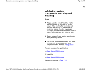
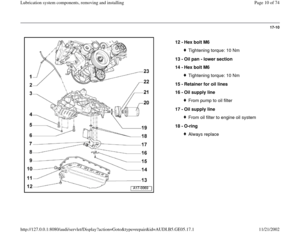
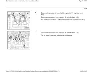
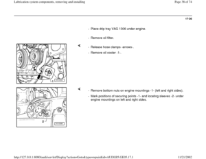
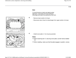
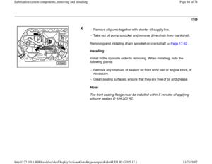
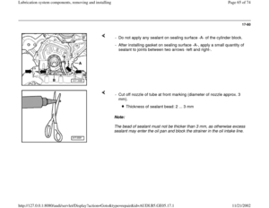
- Do not apply any sealant on sealing surface -A- of the cylinder block.
- After installing gasket on sealing surface -A-, apply a small quantity of
sealant to joints between two arrows -left and right-.
Note:
The bead of sealant must not be thicker than 3 mm, as otherwise excess
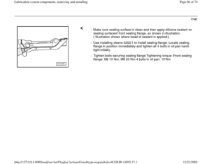
sealant may enter the oil pan and block the strainer in the oil intake line. - Cut off nozzle of tube at front marking (diameter of nozzle approx. 3
mm).
Thickness of sealant bead: 2 ... 3 mm
Pa
ge 65 of 74 Lubrication s
ystem com
ponents, removin
g and installin
g
11/21/2002 htt
p://127.0.0.1:8080/audi/servlet/Dis
play?action=Goto&t
yp
e=re
pair&id=AUDI.B5.GE05.17.1
Page 66 of 74
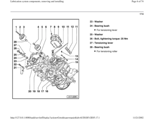
17-61
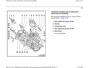
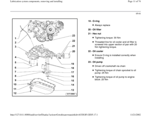
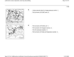
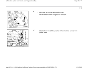
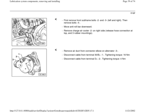
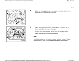
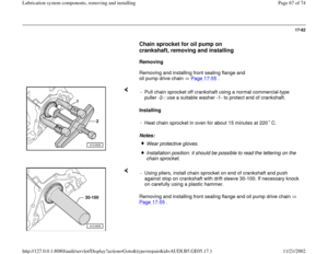
- Make sure sealing surface is clean and then apply silicone sealant on
sealing surfaceof front sealing flange, as shown in illustration.
( Illustration shows where bead of sealant is applied.)
- Use installing sleeve 3202/1 to install sealing flange. Locate sealing
flange in position immediately and tighten all 4 bolts in oil pan hand-
tight initially.
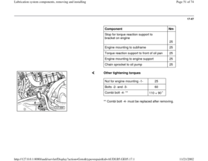
- Tighten bolts securing sealing flange Tightening torque: Front sealing
flange: M6 10 Nm, M8 20 Nm 4 bolts in oil pan: 10 Nm
Pa
ge 66 of 74 Lubrication s
ystem com
ponents, removin
g and installin
g
11/21/2002 htt
p://127.0.0.1:8080/audi/servlet/Dis
play?action=Goto&t
yp
e=re
pair&id=AUDI.B5.GE05.17.1
Page 67 of 74
17-62
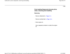
Chain sprocket for oil pump on
crankshaft, removing and installing
Removing
Removing and installing front sealing flange and
oil pump drive chain Page 17
-55
.
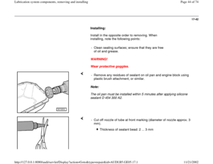
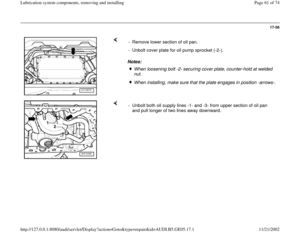
Installing
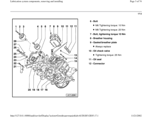
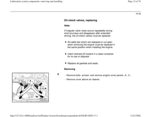
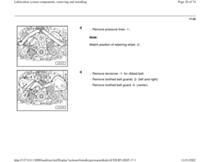
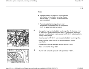
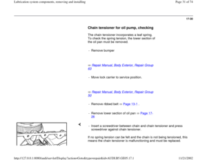
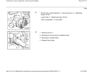
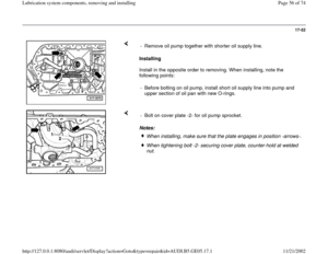
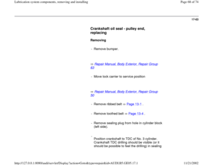
Notes: - Pull chain sprocket off crankshaft using a normal commercial-type
puller -2-: use a suitable washer -1- to protect end of crankshaft.
-
Heat chain sprocket in oven for about 15 minutes at 220 C.
Wear protective gloves. Installation position: it should be possible to read the lettering on the
chain sprocket.
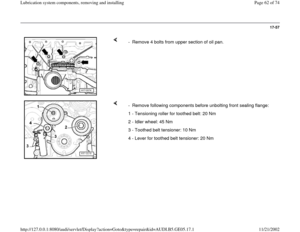
Removing and installing front sealing flange and oil pump drive chain
Page 17
-55
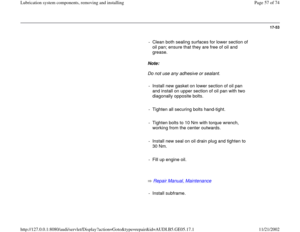
. - Using pliers, install chain sprocket on end of crankshaft and push
against stop on crankshaft with drift sleeve 30-100. If necessary knock
on carefully using a plastic hammer.
Pa
ge 67 of 74 Lubrication s
ystem com
ponents, removin
g and installin
g
11/21/2002 htt
p://127.0.0.1:8080/audi/servlet/Dis
play?action=Goto&t
yp
e=re
pair&id=AUDI.B5.GE05.17.1
Page 68 of 74
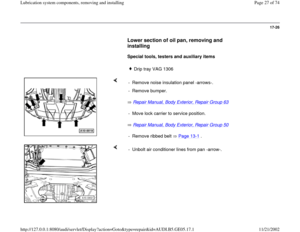
17-63
Crankshaft oil seal - pulley end,
replacing
Removing
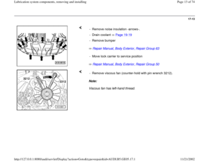
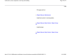
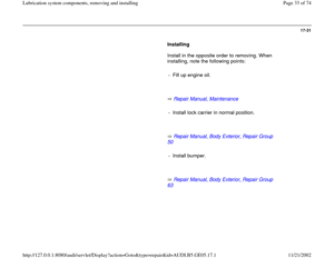
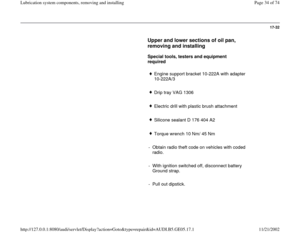
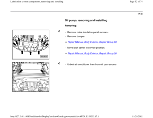
- Remove bumper.
Repair Manual, Body Exterior, Repair Group
63
- Move lock carrier to service position
Repair Manual, Body Exterior, Repair Group
50
- Remove ribbed belt Page 13
-1 .
- Remove toothed belt Page 13
-4 .
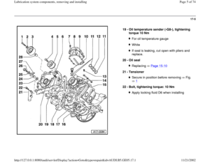
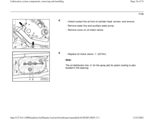
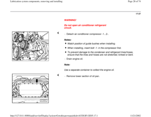
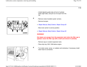
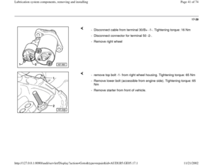
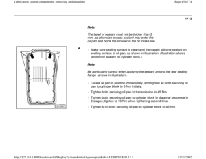
- Remove sealing plug from hole in cylinder block
(left side).
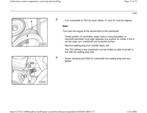
-
Position crankshaft to TDC of No. 3 cylinder.
Crankshaft TDC drilling should be visible (or it
should be possible to feel the drilling) in sealing
Pa
ge 68 of 74 Lubrication s
ystem com
ponents, removin
g and installin
g
11/21/2002 htt
p://127.0.0.1:8080/audi/servlet/Dis
play?action=Goto&t
yp
e=re
pair&id=AUDI.B5.GE05.17.1
Page 69 of 74
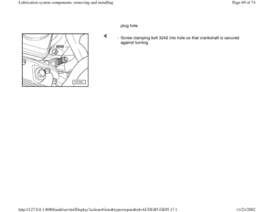
plug hole.
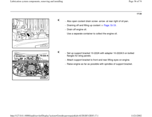
- Screw clamping bolt 3242 into hole so that crankshaft is secured
against turning.
Pa
ge 69 of 74 Lubrication s
ystem com
ponents, removin
g and installin
g
11/21/2002 htt
p://127.0.0.1:8080/audi/servlet/Dis
play?action=Goto&t
yp
e=re
pair&id=AUDI.B5.GE05.17.1
Page 70 of 74
17-64
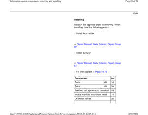
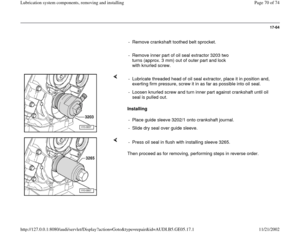
- Remove crankshaft toothed belt sprocket.
- Remove inner part of oil seal extractor 3203 two
turns (approx. 3 mm) out of outer part and lock
with knurled screw.
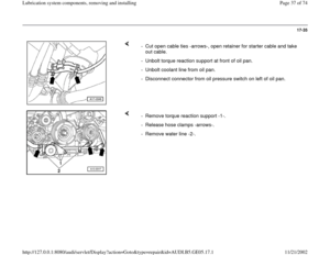
Installing - Lubricate threaded head of oil seal extractor, place it in position and,
exerting firm pressure, screw it in as far as possible into oil seal.
- Loosen knurled screw and turn inner part against crankshaft until oil
seal is pulled out.
- Place guide sleeve 3202/1 onto crankshaft journal.
- Slide dry seal over guide sleeve.
Then proceed as for removing, performing steps in reverse order. - Press oil seal in flush with installing sleeve 3265.
Pa
ge 70 of 74 Lubrication s
ystem com
ponents, removin
g and installin
g
11/21/2002 htt
p://127.0.0.1:8080/audi/servlet/Dis
play?action=Goto&t
yp
e=re
pair&id=AUDI.B5.GE05.17.1
Page 71 of 74
17-65
Oil pressure and oil pressure switch,
checking
Note:
Servicing and checking function of oil pressure
warning lamp and buzzer:
Electrical Wiring Diagrams, Troubleshooting &
Component Locations
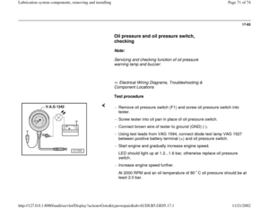
Test procedure
- Remove oil pressure switch (F1) and screw oil pressure switch into
tester.
- Screw tester into oil pan in place of oil pressure switch.
- Connect brown wire of tester to ground (GND) (-).
- Using test leads from VAG 1594, connect diode test lamp VAG 1527
between positive battery terminal (+) and oil pressure switch.
- Start engine and gradually increase engine speed.
LED should light up at 1.2...1.6 bar, otherwise replace oil pressure
switch.
- Increase engine speed further.
At 2000 RPM and an oil temperature of 80 C oil pressure should be at
least 2.0 bar.
Pa
ge 71 of 74 Lubrication s
ystem com
ponents, removin
g and installin
g
11/21/2002 htt
p://127.0.0.1:8080/audi/servlet/Dis
play?action=Goto&t
yp
e=re
pair&id=AUDI.B5.GE05.17.1
Page 72 of 74
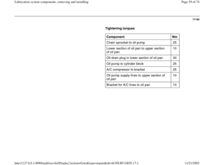
17-66
Engine oil, specifications
A high-quality multigrade oil is put in at the
factory: this can be used all year round, except in
extremely cold climates.
Viscosity grades and oil specifications
Viscosity grades and oil specifications
Repair Manual, Maintenance
Pa
ge 72 of 74 Lubrication s
ystem com
ponents, removin
g and installin
g
11/21/2002 htt
p://127.0.0.1:8080/audi/servlet/Dis
play?action=Goto&t
yp
e=re
pair&id=AUDI.B5.GE05.17.1


 out of outer part and lock
with knurled screw.
Installin")

