1997 ACURA NSX sensor
[x] Cancel search: sensorPage 438 of 1503
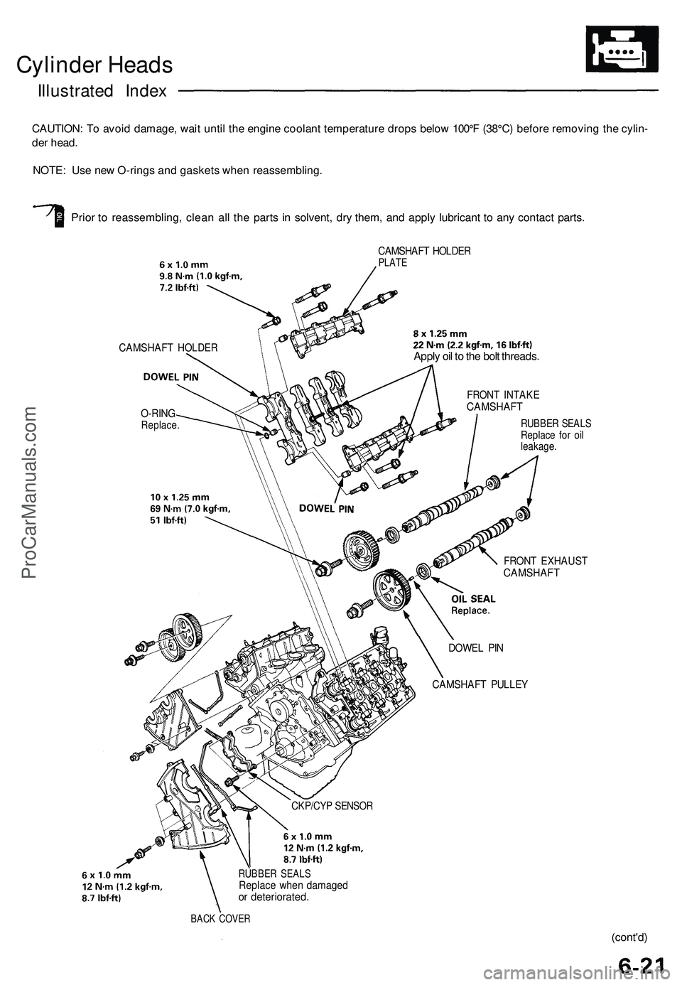
Cylinder Heads
Illustrated Index
CAUTION: To avoid damage, wait until the engine coolant temperature drops below 100°F (38°C) before removing the cylin-
der head.
NOTE: Use new O-rings and gaskets when reassembling.
Prior to reassembling, clean all the parts in solvent, dry them, and apply lubricant to any contact parts.
CAMSHAFT HOLDER
O-RING
Replace.
CAMSHAFT HOLDER
PLATE
CKP/CYP SENSOR
RUBBER SEALS
Replace when damaged
or deteriorated.
BACK COVER
Apply oil to the bolt threads.
FRONT INTAKE
CAMSHAFT
RUBBER SEALS
Replace for oil
leakage.
FRONT EXHAUST
CAMSHAFT
DOWEL PIN
CAMSHAFT PULLEY
(cont'd)ProCarManuals.com
Page 467 of 1503
Cylinder Heads
Installation (cont'd)
Rear:
8 x
1.25
mm
22 N-m (2.2 kgf-m,
16 Ibf-ft)
REAR PRIMARY
HEATED OXYGEN SENSOR
(REAR PRIMARY HO2S)
44 N-m (4.5 kgf-m,
33 Ibf-ft)
Be careful not to damage.
GASKET
Replace.
REAR EXHAUST
MANIFOLD
EXHAUST
MANIFOLD
COVER
SELF-LOCKING NUT
8 x
1.25
mm
30 N-m (3.1 kgf-m,
22 Ibf-ft)
Replace.
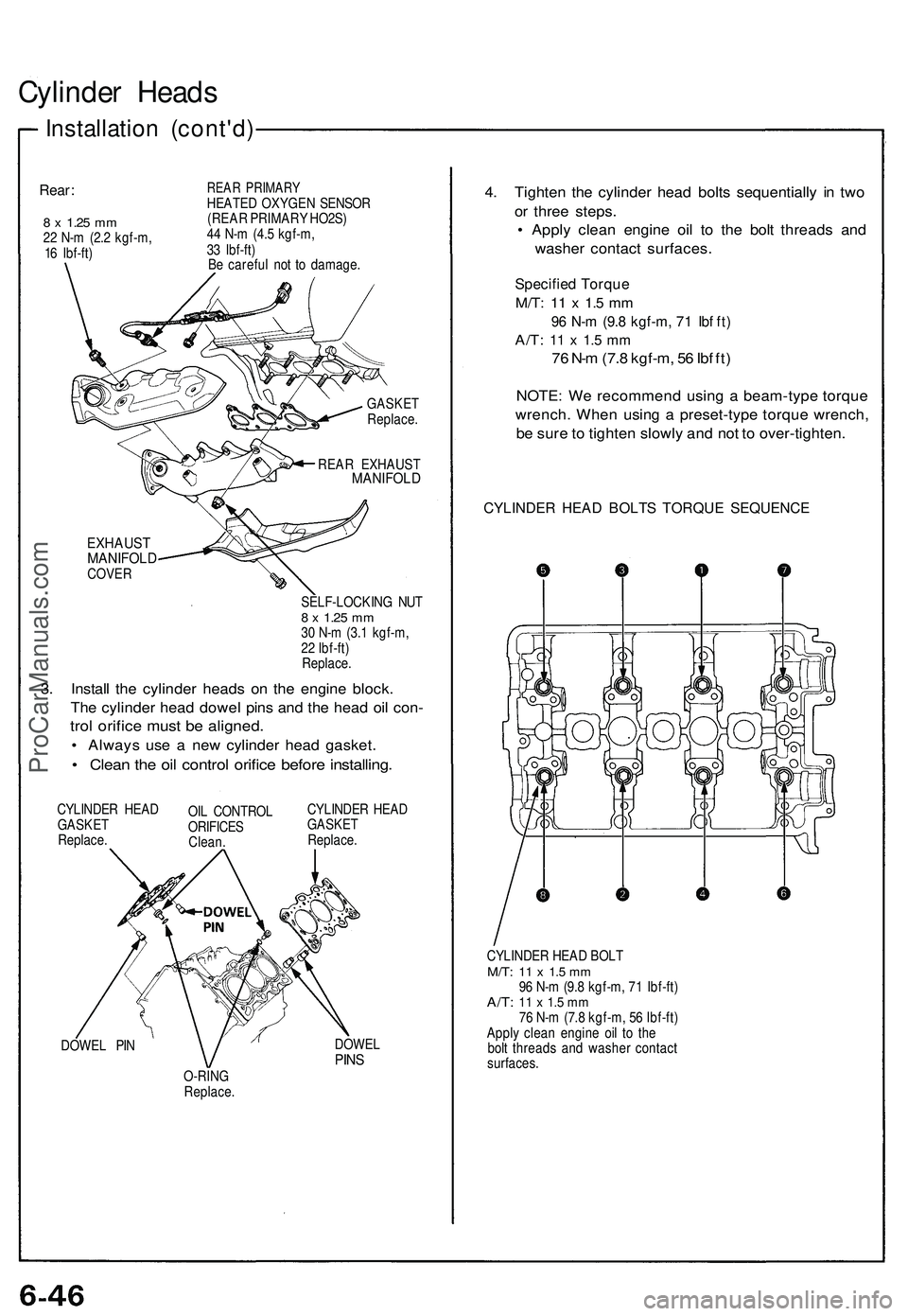
3. Install the cylinder heads on the engine block.
The cylinder head dowel pins and the head oil con-
trol orifice must be aligned.
• Always use a new cylinder head gasket.
• Clean the oil control orifice before installing.
CYLINDER HEAD
GASKET
Replace.
OIL CONTROL
ORIFICES
Clean.
CYLINDER HEAD
GASKET
Replace.
DOWEL PIN
DOWEL
PINS
O-RING
Replace.
4. Tighten the cylinder head bolts sequentially in two
or three steps.
• Apply clean engine oil to the bolt threads and
washer contact surfaces.
Specified Torque
M/T:
11 x 1.5 mm
96 N-m (9.8 kgf-m, 71 Ibf ft)
A/T:
11 x 1.5 mm
76 N-m (7.8 kgf-m, 56 Ibf ft)
NOTE: We recommend using a beam-type torque
wrench. When using a preset-type torque wrench,
be sure to tighten slowly and not to over-tighten.
CYLINDER HEAD BOLTS TORQUE SEQUENCE
CYLINDER HEAD BOLT
M/T:
11 x 1.5 mm
96 N-m (9.8 kgf-m, 71 Ibf-ft)
A/T:
11 x 1.5 mm
76 N-m (7.8 kgf-m, 56 Ibf-ft)
Apply clean engine oil to the
bolt threads and washer contact
surfaces.ProCarManuals.com
Page 516 of 1503
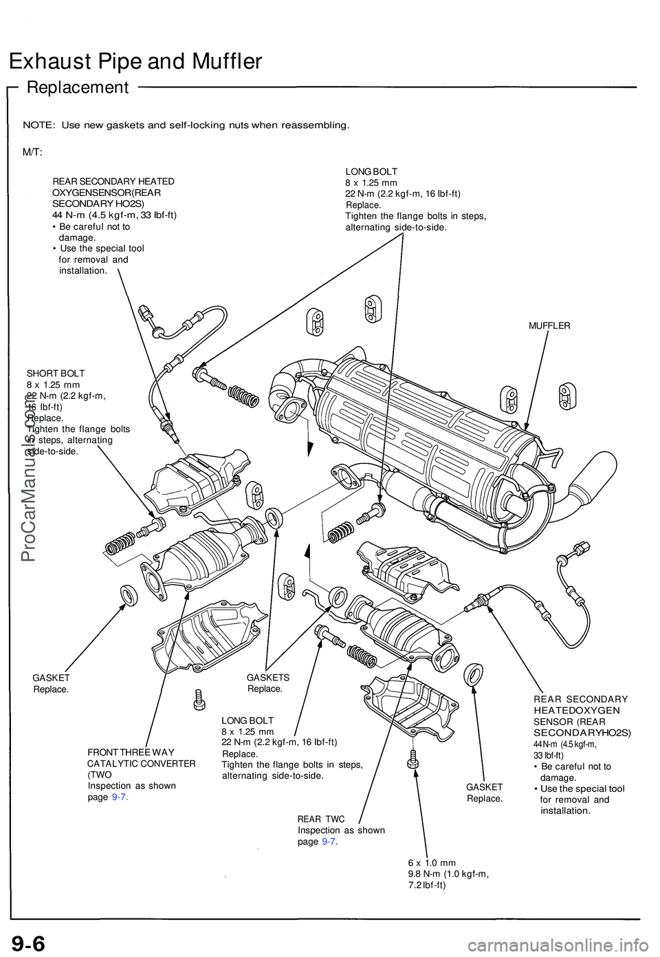
Exhaust Pip e an d Muffle r
Replacemen t
NOTE: Us e ne w gasket s an d self-lockin g nut s whe n reassembling .
M/T:
REAR SECONDARY HEATEDOXYGEN SENSOR (REARSECONDARY HO2S )
4 4 N- m (4.5 kgf-m , 3 3 Ibf-ft )
• B e carefu l no t t o
damage .
• Us e th e specia l too l
fo r remova l an d
installation . LON
G BOL T
8 x 1.2 5 mm22 N- m (2. 2 kgf-m , 1 6 Ibf-ft )Replace .Tighten th e flang e bolts in steps ,
alternatin g side-to-side .
MUFFLER
SHORT BOL T8 x 1.2 5 mm22 N- m (2. 2 kgf-m ,16 Ibf-ft )Replace .Tighten th e flang e bolt s
i n steps , alternatin g
side-to-side .
GASKETReplace .
FRON T THRE E WA Y
CATALYTI C CONVERTE R(TWOInspectio n a s show n
pag e 9-7.GASKE TReplace .
REAR TW CInspectio n a s show n
page 9-7. REA
R SECONDAR Y
HEATED OXYGE NSENSOR (REA RSECONDAR Y HO2S )44 N-m (4.5 kgf-m,33 Ibf-ft)• B e carefu l no t t o
damage .
• Us e th e specia l too lfor remova l an dinstallation .
6 x 1. 0 m m9.8 N- m (1. 0 kgf-m ,
7. 2 Ibf-ft )
GASKET SReplace.
LON G BOL T
8 x 1.2 5 mm22 N- m (2. 2 kgf-m , 1 6 Ibf-ft )Replace .Tighten th e flang e bolt s i n steps ,
alternatin g side-to-side .
ProCarManuals.com
Page 529 of 1503
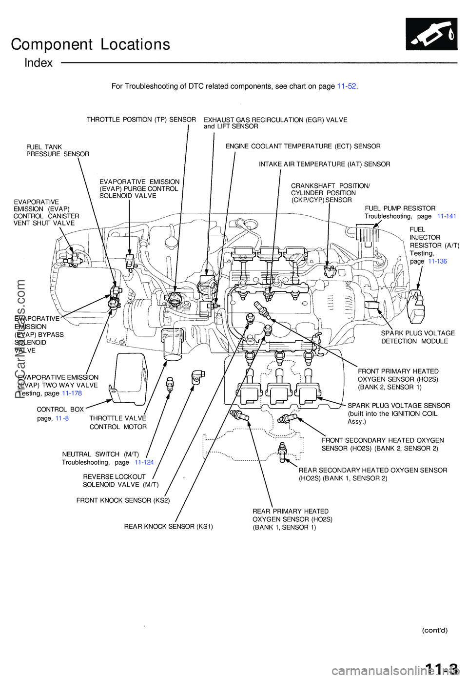
Component Location s
Index
THROTTL E POSITIO N (TP ) SENSO R
FUE L TAN K
PRESSUR E SENSO R
EVAPORATIV E
EMISSIO N (EVAP )
CONTRO L CANISTE R
VEN T SHU T VALV E EXHAUS
T GA S RECIRCULATIO N (EGR ) VALV E
an d LIF T SENSO R
ENGIN E COOLAN T TEMPERATUR E (ECT ) SENSO R
INTAK E AI R TEMPERATUR E (IAT ) SENSO R
CRANKSHAF T POSITION /
CYLINDE R POSITIO N
(CKP/CYP ) SENSO R
FUEL PUM P RESISTO R
Troubleshooting , pag e 11-14 1
FUE L
INJECTO R
RESISTO R (A/T )
Testing ,page 11-13 6
EVAPORATIV
E EMISSIO N
(EVAP ) PURG E CONTRO L
SOLENOI D VALV E
EVAPORATIV E
EMISSION(EVAP) BYPAS S
SOLENOI D
VALV E
EVAPORATIV E EMISSIO N(EVAP) TW O WA Y VALV ETesting , pag e 11-17 8
CONTRO L BO X
page , 1 1 -8 THROTTL E VALV E
CONTRO L MOTO R
NEUTRA L SWITC H (M/T )
Troubleshooting , pag e 11-12 4
REVERS E LOCKOU T
SOLENOI D VALV E (M/T )
FRON T KNOC K SENSO R (KS2 ) SPAR
K PLU G VOLTAG E
DETECTIO N MODUL E
FRON T PRIMAR Y HEATE D
OXYGEN SENSOR (HO2S )
(BAN K 2 , SENSO R 1 )
SPAR K PLU G VOLTAG E SENSO R(built int o th e IGNITIO N COI LAssy. )
FRONT SECONDAR Y HEATE D OXYGE N
SENSO R (HO2S ) (BAN K 2 , SENSO R 2 )
REAR SECONDARY HEATED OXYGEN SENSOR (HO2S) (BANK 1, SENSOR 2)
REA R KNOC K SENSO R (KS1 )
REAR PRIMAR Y HEATE DOXYGEN SENSO R (HO2S )
(BAN K 1 , SENSO R 1 )
(cont'd )
For Troubleshooting of DTC related components, see chart on page 11-52.
ProCarManuals.com
Page 535 of 1503
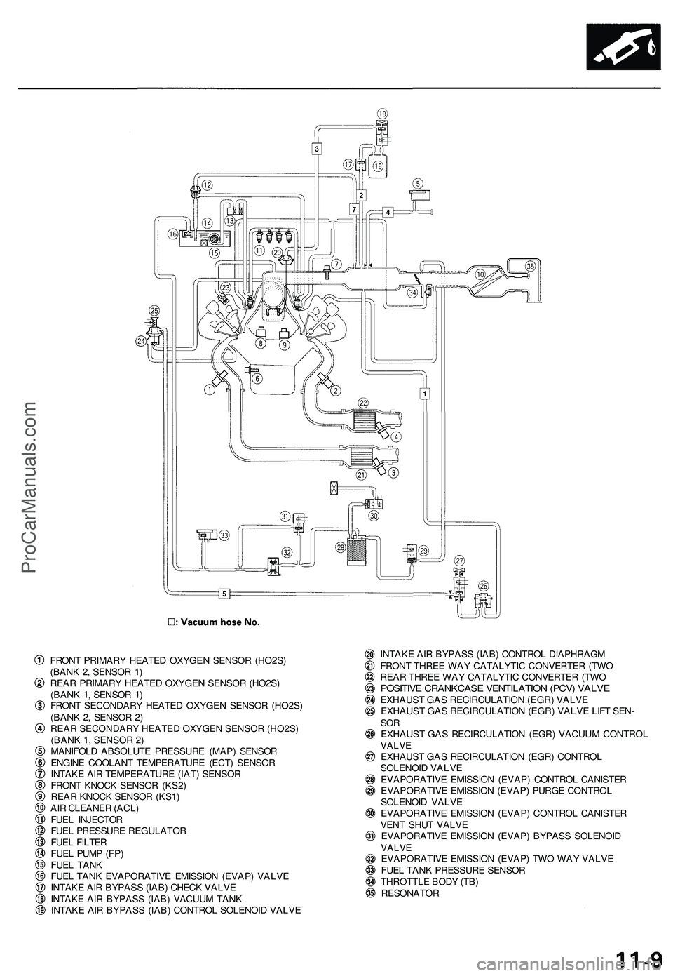
FRONT PRIMAR Y HEATE D OXYGE N SENSO R (HO2S )
(BAN K 2 , SENSO R 1 )
REA R PRIMAR Y HEATE D OXYGE N SENSO R (HO2S )
(BAN K 1 , SENSO R 1 )
FRON T SECONDAR Y HEATE D OXYGE N SENSO R (HO2S )
(BAN K 2 , SENSO R 2 )
REAR SECONDARY HEATED OXYGEN SENSOR (HO2S)
(BANK 1, SENSOR 2)
MANIFOL D ABSOLUT E PRESSUR E (MAP ) SENSO R
ENGIN E COOLAN T TEMPERATUR E (ECT ) SENSO R
INTAK E AI R TEMPERATUR E (IAT ) SENSO R
FRON T KNOC K SENSO R (KS2 )
REA R KNOC K SENSO R (KS1 )
AI R CLEANE R (ACL )
FUE L INJECTO R
FUE L PRESSUR E REGULATO R
FUE L FILTE R
FUE L PUM P (FP )
FUE L TAN K
FUE L TAN K EVAPORATIV E EMISSIO N (EVAP ) VALV E
INTAK E AI R BYPAS S (IAB ) CHEC K VALV E
INTAK E AI R BYPAS S (IAB ) VACUU M TAN K
INTAK E AI R BYPAS S (IAB ) CONTRO L SOLENOI D VALV E INTAK
E AI R BYPAS S (IAB ) CONTRO L DIAPHRAG M
FRON T THRE E WA Y CATALYTI C CONVERTE R (TW O
REA R THRE E WA Y CATALYTI C CONVERTE R (TW O
POSITIV E CRANKCAS E VENTILATIO N (PCV ) VALV EEXHAUS T GA S RECIRCULATIO N (EGR ) VALV E
EXHAUS T GA S RECIRCULATIO N (EGR ) VALV E LIF T SEN -
SOREXHAUS T GA S RECIRCULATIO N (EGR ) VACUU M CONTRO LVALVEEXHAUS T GA S RECIRCULATIO N (EGR ) CONTRO L
SOLENOI D VALV E
EVAPORATIV E EMISSIO N (EVAP ) CONTRO L CANISTE R
EVAPORATIV E EMISSIO N (EVAP ) PURG E CONTRO L
SOLENOI D VALV E
EVAPORATIV E EMISSIO N (EVAP ) CONTRO L CANISTE R
VEN T SHU T VALV E
EVAPORATIV E EMISSIO N (EVAP ) BYPAS S SOLENOI D
VALVEEVAPORATIV E EMISSIO N (EVAP ) TW O WA Y VALV E
FUE L TAN K PRESSUR E SENSO R
THROTTL E BOD Y (TB )
RESONATO R
ProCarManuals.com
Page 570 of 1503
Troubleshooting
Troubleshooting Procedures (cont'd)
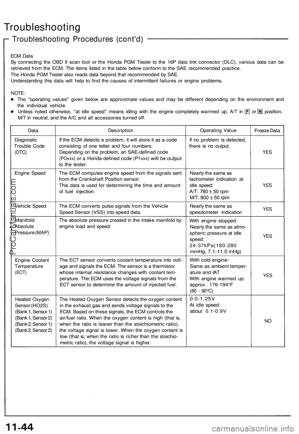
ECM Data
By connecting the OBD II scan tool or the Honda PGM Tester to the 16P data link connector (DLC), various data can be
retrieved from the ECM. The items listed in the table below conform to the SAE recommended practice.
The Honda PGM Tester also reads data beyond that recommended by SAE.
Understanding this data will help to find the causes of intermittent failures or engine problems.
NOTE:
The "operating values" given below are approximate values and may be different depending on the environment and
the individual vehicle.
Unless noted otherwise, "at idle speed" means idling with the engine completely warmed up, A/T in or position,
M/T in neutral, and the A/C and all accessories turned off.
Data
Description
Operating Value
Freeze Data
Diagnostic
Trouble Code
(DTC)
If the ECM detects a problem, it will store it as a code
consisting of one letter and four numbers.
Depending on the problem, an SAE-defined code
(POxxx)
or a
Honda-defined code
(P1xxx)
will
be
output
to the tester.
If no problem is detected,
there is no output.
YES
Engine Speed
The ECM computes engine speed from the signals sent
from the Crankshaft Position sensor.
This data is used for determining the time and amount
of fuel injection.
Nearly the same as
tachometer indication at
idle speed:
A/T:
780 ± 50 rpm
M/T:
800 ± 50 rpm
YES
Vehicle Speed
The ECM converts pulse signals from the Vehicle
Speed Sensor (VSS) into speed data.
Nearly the same as
speedometer indication
YES
Manifold
Absolute
Pressure (MAP)
The absolute pressure created in the intake manifold by
engine load and speed.
With engine stopped:
Nearly the same as atmo-
spheric pressure at idle
speed:
24-37kPa(180-280
mmHg, 7.1-11.0 inHg)
YES
Engine Coolant
Temperature
(ECT)
The ECT sensor converts coolant temperature into volt-
age and signals the ECM. The sensor is a thermistor
whose internal resistance changes with coolant tem-
perature. The ECM uses the voltage signals from the
ECT sensor to determine the amount of injected fuel.
With cold engine:
Same as ambient temper-
ature and IAT
With engine warmed up:
approx. 176-194°F
(80 - 90°C)
YES
Heated Oxygen
Sensor (HO2S)
(Bank 1, Sensor 1)
(Bank 1, Sensor 2)
(Bank 2, Sensor 1)
(Bank 2, Sensor 2)
The Heated Oxygen Sensor detects the oxygen content
in the exhaust gas and sends voltage signals to the
ECM. Based on these signals, the ECM controls the
air/fuel ratio. When the oxygen content is high (that is,
when the ratio is leaner than the stoichiometric ratio),
the voltage signal is lower. When the oxygen content is
low (that is, when the ratio is richer than the stoichio-
metric ratio), the voltage signal is higher.
0.0-1.25V
At idle speed:
about 0.1-0.9V
NOProCarManuals.com
Page 571 of 1503
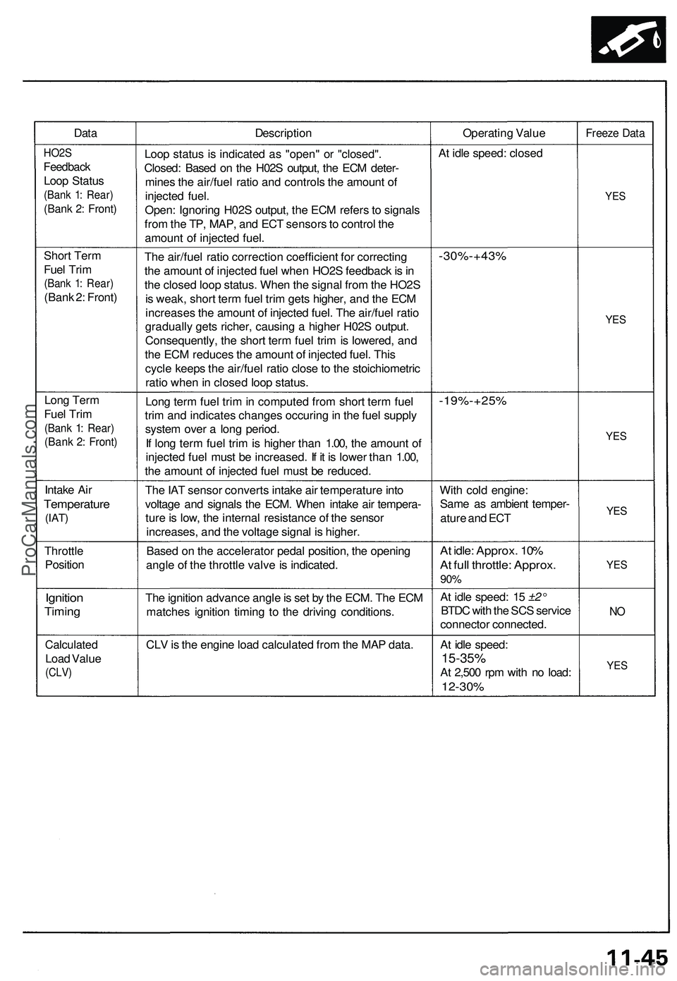
DataDescriptio nOperating Valu eFreez e Dat a
HO2 S
Feedbac k
Loop Statu s
(Bank 1 : Rear )
(Bank 2 : Front )
Loop statu s i s indicate d a s "open " o r "closed" .
Closed : Base d o n th e H02 S output , th e EC M deter -
mine s th e air/fue l rati o an d control s th e amoun t o f
injecte d fuel .
Open : Ignorin g H02 S output , th e EC M refer s t o signal s
fro m th e TP , MAP , an d EC T sensor s to contro l th e
amoun t o f injecte d fuel . A
t idl e speed : close d
YES
Shor t Ter m
Fue l Tri m
(Ban k 1 : Rear )
(Bank 2 : Front ) Th
e air/fue l rati o correctio n coefficien t fo r correctin g
th e amoun t o f injecte d fue l whe n HO2 S feedbac k is in
th e close d loo p status . Whe n th e signa l fro m th e HO2 S
i s weak , shor t ter m fue l tri m get s higher , an d th e EC M
increase s th e amoun t o f injecte d fuel . Th e air/fue l rati o
graduall y get s richer , causin g a highe r H02 S output .
Consequently , th e shor t ter m fue l tri m is lowered , an d
th e EC M reduce s th e amoun t o f injecte d fuel . Thi s
cycl e keep s th e air/fue l rati o clos e to th e stoichiometri c
rati o whe n in close d loo p status .
-30%-+43 %
YES
Lon g Ter m
Fue l Tri m
(Ban k 1 : Rear )
(Bank 2 : Front )
Long ter m fue l tri m in compute d fro m shor t ter m fue l
tri m an d indicate s change s occurin g in th e fue l suppl y
syste m ove r a lon g period .
I f lon g ter m fue l tri m is highe r tha n 1.00 , th e amoun t o f
injecte d fue l mus t b e increased . I f i t i s lowe r tha n 1.00 ,
th e amoun t o f injecte d fue l mus t b e reduced .-19%-+25 %
YES
Intak e Ai r
Temperatur e
(IAT)
The IA T senso r convert s intak e ai r temperatur e int o
voltag e an d signal s th e ECM . Whe n intak e ai r tempera -
tur e is low , th e interna l resistanc e o f th e senso r
increases , an d th e voltag e signa l i s higher . Wit
h col d engine :
Sam e a s ambien t temper -
atur e an d EC T
YES
Throttl e
Positio n Base
d o n th e accelerato r peda l position , th e openin g
angl e o f th e throttl e valv e is indicated .At idle : Approx . 10 %
At ful l throttle : Approx .
90%
YE S
Ignitio n
Timing
The ignitio n advanc e angl e is se t b y th e ECM . Th e EC M
matche s ignitio n timin g t o th e drivin g conditions .A
t idl e speed : 1 5 ±2°
BTD C wit h th e SC S servic e
connecto r connected .
NO
Calculate d
Load Valu e
(CLV )
CLV is th e engin e loa d calculate d fro m th e MA P data . At idl e speed :
15-35%
At 2,50 0 rp m wit h n o load :
12-30 %
YES
ProCarManuals.com
Page 572 of 1503
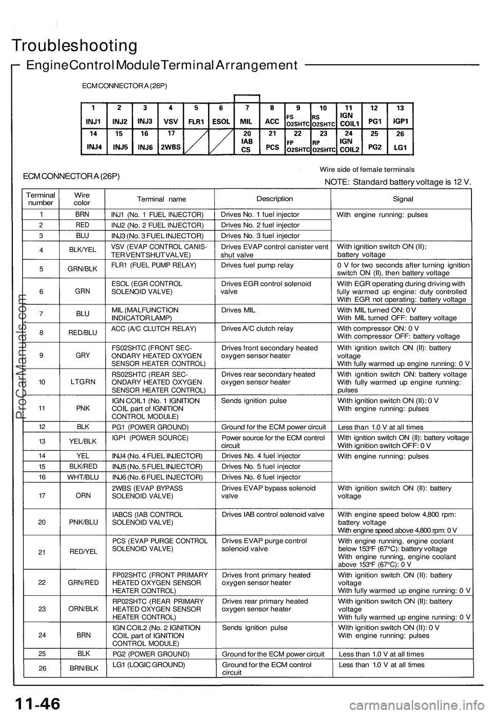
Troubleshooting
Engine Control Module Terminal Arrangement
ECM CONNECTOR A (26P)
ECM CONNECTOR A (26P)
Wire side of female terminals
NOTE: Standard battery voltage is 12 V.
Terminal
number
1
2
3
4
5
6
7
8
9
10
11
12
13
14
15
16
17
20
21
22
23
24
25
26
Wire
color
BRN
RED
BLU
BLK/YEL
GRN/BLK
GRN
BLU
RED/BLU
GRY
LTGRN
PNK
BLK
YEL/BLK
YEL
BLK/RED
WHT/BLU
ORN
PNK/BLU
RED/YEL
GRN/RED
ORN/BLK
BRN
BLK
BRN/BLK
Terminal name
INJ1 (No. 1 FUEL INJECTOR)
INJ2 (No. 2 FUEL INJECTOR)
INJ3 (No. 3 FUEL INJECTOR)
VSV (EVAP CONTROL CANIS-
TER VENT SHUT VALVE)
FLR1 (FUEL PUMP RELAY)
ESOL (EGR CONTROL
SOLENOID VALVE)
MIL (MALFUNCTION
INDICATOR LAMP)
ACC (A/C CLUTCH RELAY)
FS02SHTC (FRONT SEC-
ONDARY HEATED OXYGEN
SENSOR HEATER CONTROL)
RS02SHTC (REAR SEC-
ONDARY HEATED OXYGEN
SENSOR HEATER CONTROL)
IGN COIL1 (No. 1 IGNITION
COIL part of IGNITION
CONTROL MODULE)
PG1 (POWER GROUND)
IGP1 (POWER SOURCE)
INJ4 (No. 4 FUEL INJECTOR)
INJ5 (No. 5 FUEL INJECTOR)
INJ6 (No. 6 FUEL INJECTOR)
2WBS (EVAP BYPASS
SOLENOID VALVE)
IABCS (IAB CONTROL
SOLENOID VALVE)
PCS (EVAP PURGE CONTROL
SOLENOID VALVE)
FP02SHTC (FRONT PRIMARY
HEATED OXYGEN SENSOR
HEATER CONTROL)
RP02SHTC (REAR PRIMARY
HEATED OXYGEN SENSOR
HEATER CONTROL)
IGN COIL2 (No. 2 IGNITION
COIL part of IGNITION
CONTROL MODULE)
PG2 (POWER GROUND)
LG1 (LOGIC GROUND)
Description
Drives No. 1 fuel injector
Drives No. 2 fuel injector
Drives No. 3 fuel injector
Drives EVAP control canister vent
shut valve
Drives fuel pump relay
Drives EGR control solenoid
valve
Drives MIL
Drives A/C clutch relay
Drives front secondary heated
oxygen sensor heater
Drives rear secondary heated
oxygen sensor heater
Sends ignition pulse
Ground for the ECM power circuit
Power source for the ECM control
circuit
Drives No. 4 fuel injector
Drives No. 5 fuel injector
Drives No. 6 fuel injector
Drives EVAP bypass solenoid
valve
Drives IAB control solenoid valve
Drives EVAP purge control
solenoid valve
Drives front primary heated
oxygen sensor heater
Drives rear primary heated
oxygen sensor heater
Sends ignition pulse
Ground for the ECM power circuit
Ground for the ECM control
circuit
Signal
With engine running: pulses
With ignition switch ON (II):
battery voltage
0 V for two seconds after turning ignition
switch ON (II), then battery voltage
With EGR operating during driving with
fully warmed up engine: duty controlled
With EGR not operating: battery voltage
With MIL turned ON: 0V
With MIL turned OFF: battery voltage
With compressor ON: 0 V
With compressor OFF: battery voltage
With ignition switch ON (II): battery
voltage
With fully warmed up engine running: 0 V
With ignition switch ON: battery voltage
With fully warmed up engine running:
pulses
With ignition switch ON (II): 0 V
With engine running: pulses
Less than 1.0 V at all times
With ignition switch ON (II): battery voltage
With ignition switch OFF: 0 V
With engine running: pulses
With ignition switch ON (II): battery
voltage
With engine speed below 4,800 rpm:
battery voltage
With engine speed above 4,800 rpm: 0 V
With engine running, engine coolant
below 153°F (67°C): battery voltage
With engine running, engine coolant
above 153°F (67°C): 0 V
With ignition switch ON (II): battery
voltage
With fully warmed up engine running: 0 V
With ignition switch ON (II): battery
voltage
With fully warmed up engine running: 0 V
With ignition switch ON (II): 0 V
With engine running: pulses
Less than 1.0 V at all times
Less than 1.0 V at all timesProCarManuals.com