Page 1259 of 1503

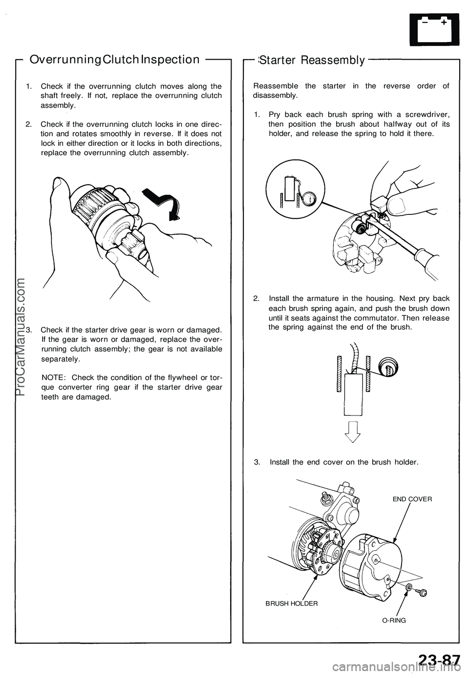
Overrunning Clutch Inspection
1. Check if the overrunning clutch moves along the
shaft freely. If not, replace the overrunning clutch
assembly.
2. Check if the overrunning clutch locks in one direc-
tion and rotates smoothly in reverse. If it does not
lock in either direction or it locks in both directions,
replace the overrunning clutch assembly.
3. Check if the starter drive gear is worn or damaged.
If the gear is worn or damaged, replace the over-
running clutch assembly; the gear is not available
separately.
NOTE: Check the condition of the flywheel or tor-
que converter ring gear if the starter drive gear
teeth are damaged.
Starter Reassembly
Reassemble the starter in the reverse order of
disassembly.
1. Pry back each brush spring with a screwdriver,
then position the brush about halfway out of its
holder, and release the spring to hold it there.
2. Install the armature in the housing. Next pry back
each brush spring again, and push the brush down
until it seats against the commutator. Then release
the spring against the end of the brush.
3. Install the end cover on the brush holder.
END COVER
BRUSH HOLDER
O-RINGProCarManuals.com
Page 1422 of 1503
Power Seats
Seat Switch Test
CAUTION: Be careful not to damage the seats, the
interior trim or the body.
1. Remove the two screws, then remove the power
seat switch from the power seat.
2. Disconnect the 5P connectors from each power seat
switch.
3. Check for continuity between the terminals, in each
switch position, according to the table.
RECLINE
SWITCH
SLIDE
SWITCH
SLIDE
RECLINE
Position
Terminal
FORWARD
NEUTRAL
BACKWARD
FORWARD
NEUTRAL
BACKWARDProCarManuals.com
Page 1423 of 1503

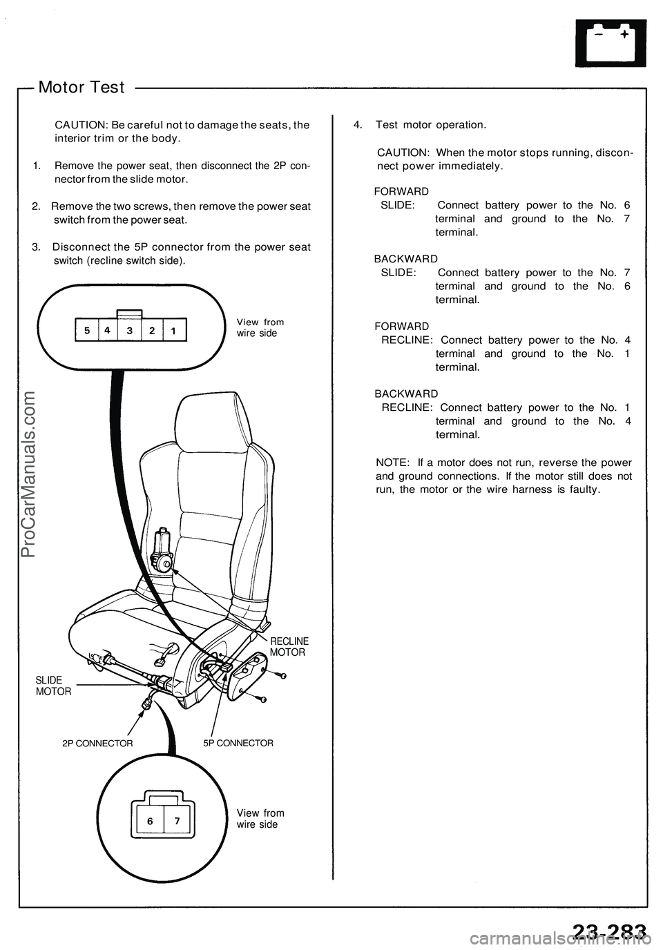
Motor Test
CAUTION: Be careful not to damage the seats, the
interior trim or the body.
1. Remove the power seat, then disconnect the 2P con-
nector from the slide motor.
2. Remove the two screws, then remove the power seat
switch from the power seat.
3. Disconnect the 5P connector from the power seat
switch (recline switch side).
View from
wire side
RECLINE
MOTOR
SLIDE
MOTOR
View from
wire side
4. Test motor operation.
CAUTION: When the motor stops running, discon-
nect power immediately.
FORWARD
SLIDE: Connect battery power to the No. 6
terminal and ground to the No. 7
terminal.
BACKWARD
SLIDE: Connect battery power to the No. 7
terminal and ground to the No. 6
terminal.
FORWARD
RECLINE: Connect battery power to the No. 4
terminal and ground to the No. 1
terminal.
BACKWARD
RECLINE: Connect battery power to the No. 1
terminal and ground to the No. 4
terminal.
NOTE: If a motor does not run, reverse the power
and ground connections. If the motor still does not
run, the motor or the wire harness is faulty.
2P CONNECTOR
5P CONNECTORProCarManuals.com
Page 1474 of 1503

Supplemental Restrain t Syste m (SRS )
Descriptio n
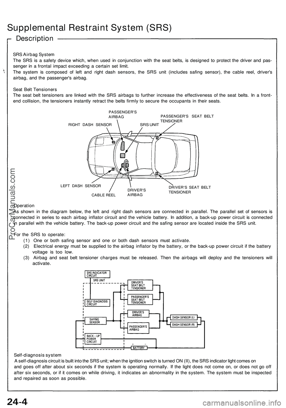
SRS Airba g Syste m
Th e SR S is a safet y devic e which , whe n use d i n conjunctio n wit h th e sea t belts , i s designe d t o protec t th e drive r an d pas -
senge r i n a fronta l impac t exceedin g a certai n se t limit .
Th e syste m is compose d o f lef t an d righ t das h sensors , th e SR S uni t (include s safin g sensor) , th e cabl e reel , driver' s
airbag , an d th e passenger' s airbag .
Sea t Bel t Tensioner s
Th e sea t bel t tensioner s ar e linke d wit h th e SR S airbag s t o furthe r increas e th e effectivenes s o f th e sea t belts . I n a front -
en d collision , th e tensioner s instantl y retrac t th e belt s firml y t o secur e th e occupant s i n thei r seats .
PASSENGER' S
AIRBA G
RIGH T DAS H SENSO R
SRS UNI T
PASSENGER' S SEA T BEL T
TENSIONE R
LEF T DAS H SENSO R
CABL E REE L DRIVER'
S
AIRBA G DRIVER'
S SEA T BEL T
TENSIONE R
Operation
A s show n i n th e diagra m below , th e lef t an d righ t das h sensor s ar e connecte d i n parallel . Th e paralle l se t o f sensor s i s
connecte d i n serie s t o eac h airba g inflato r circui t an d th e vehicl e battery . I n addition , a back-u p powe r circui t i s connecte d
i n paralle l wit h th e vehicl e battery . Th e back-u p powe r circui t an d th e safin g senso r ar e locate d insid e th e SR S unit .
Fo r th e SR S t o operate :
(1 ) On e o r bot h safin g senso r an d on e o r bot h das h sensor s mus t activate .
(2 ) Electrica l energ y mus t b e supplie d t o th e airba g inflato r b y th e battery , o r th e back-u p powe r circui t i f th e batter y
voltag e i s to o low .
(3 ) Airba g an d sea t bel t tensione r charge s mus t b e released . The n th e airbag s wil l deplo y an d th e tensioner s wil l
activate .
Self-diagnosi s syste m
A self-diagnosi s circui t i s buil t int o th e SR S unit ; whe n th e ignitio n switc h is turne d O N (II) , th e SR S indicato r ligh t come s o n
an d goe s of f afte r abou t si x second s i f th e syste m is operatin g normally . I f th e ligh t doe s no t com e on , o r doe s no t g o of f
afte r si x seconds , o r i f i t come s o n whil e driving , i t indicate s a n abnormalit y i n th e system . Th e syste m mus t b e inspecte d
an d repaire d a s soo n a s possible .
ProCarManuals.com