1997 ACURA NSX ECO mode
[x] Cancel search: ECO modePage 405 of 1503
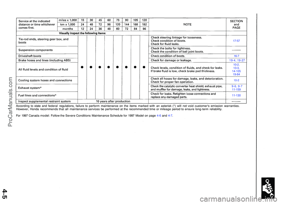
17-57
16-7
19-4, 19-2 7
10-2,
13-3 ,
14-10 519-84
10-2
9-6, 9- 711-159
11-130
Accordin g t o stat e an d federa l regulations , failur e t o perfor m maintenanc e o n th e item s marke d wit h a n asteris k (* ) wil l no t voi d customer' s emissio n warranties .
However , Hond a recommend s tha t al l maintenanc e service s b e performe d a t th e recommende d tim e o r mileag e perio d t o ensur e long-ter m reliability .
Fo r 199 7 Canad a model : Follo w th e Sever e Condition s Maintenanc e Schedule for 199 7 Mode l o n pag e 4-6 and 4-7 .
ProCarManuals.com
Page 407 of 1503
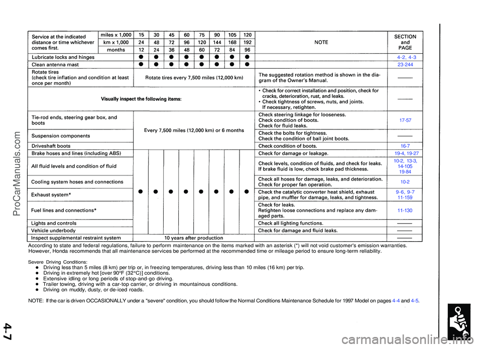
4-2, 4-3
23-244
17-57
16-7
19-4 , 19-2 7
10-2, 13-3 ,14-10 519-84
10-2
9-6, 9-711-15 9
11-130
Accordin g to stat e an d federa l regulations , failur e to perfor m maintenanc e o n th e item s marke d wit h a n asteris k (* ) wil l no t voi d customer' s emissio n warranties .
However , Hond a recommend s tha t al l maintenanc e service s b e performe d a t th e recommende d tim e o r mileag e perio d to ensur e long-ter m reliability .
Severe Drivin g Conditions :Driving les s tha n 5 mile s ( 8 km ) pe r tri p or , i n freezin g temperatures , drivin g les s tha n 1 0 mile s (1 6 km ) pe r trip .
Drivin g in extremel y ho t [ove r 90° F (32°C) ] conditions .
Extensiv e idlin g o r lon g period s o f stop-and-g o driving .
Traile r towing , drivin g wit h a car-to p carrier , o r drivin g in mountainou s conditions .
Drivin g o n muddy , dusty , o r de-ice d roads .
NOTE : I f th e ca r i s drive n OCCASIONALL Y unde r a "severe " condition , yo u shoul d follo w th e Norma l Condition s Maintenanc e Schedul e fo r 199 7 Mode l o n page s 4- 4 an d 4-5 .
ProCarManuals.com
Page 585 of 1503
PGM-FI Syste m
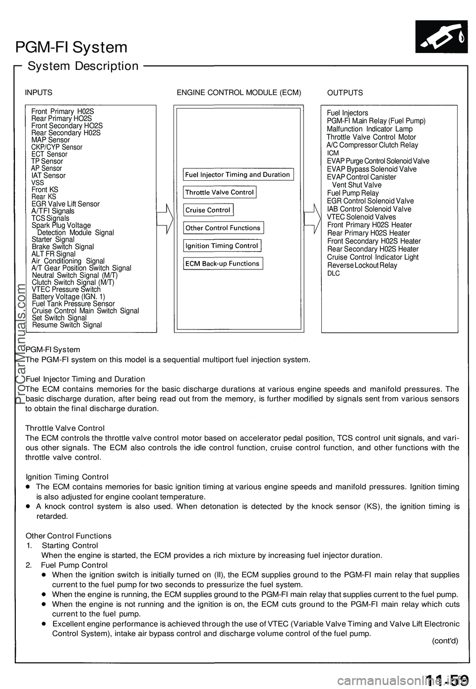
System Descriptio n
INPUTSENGIN E CONTRO L MODUL E (ECM )OUTPUT S
Front Primar y H02 S
Rea r Primar y HO2 S
Fron t Secondar y HO2 S
Rea r Secondar y H02 S
MA P Senso r
CKP/CY P Senso rECT Senso rTP Senso rAP Senso rIAT Senso rVSSFron t K SRea r K SEG R Valv e Lif t Senso rA/TFI Signal sTCS Signal s
Spar k Plu g Voltag e
Detectio n Modul e Signa l
Starte r Signa l
Brak e Switc h Signa l
AL T F R Signa l
Ai r Conditionin g Signa l
A/ T Gea r Positio n Switc h Signa l
Neutra l Switc h Signa l (M/T )
Clutc h Switc h Signa l (M/T )
VTE C Pressur e Switc h
Batter y Voltag e (IGN . 1 )
Fue l Tan k Pressur e Senso r
Cruis e Contro l Mai n Switc h Signa l
Se t Switc h Signa l
Resum e Switc h Signa l Fue
l Injector s
PGM-F I M.ai n Rela y (Fue l Pump )
Malfunctio n Indicato r Lam p
Throttl e Valv e Contro l Moto r
A/ C Compresso r Clutc h Rela y
ICMEVA P Purg e Contro l Solenoi d Valv e
EVA P Bypas s Solenoi d Valv e
EVA P Contro l Caniste r
Ven t Shu t Valv e
Fue l Pum p Rela y
EG R Contro l Solenoi d Valv e
IA B Contro l Solenoi d Valv e
VTE C Solenoi d Valve s
Fron t Primar y H02 S Heate r
Rea r Primar y H02 S Heate r
Fron t Secondar y H02 S Heate r
Rea r Secondar y H02 S Heate r
Cruis e Contro l Indicato r Ligh t
Revers e Lockou t Rela y
DLC
PGM-F I Syste m
Th e PGM-F I syste m o n thi s mode l i s a sequentia l multipor t fue l injectio n system .
Fue l Injecto r Timin g an d Duratio n
Th e EC M contain s memorie s fo r th e basi c discharg e duration s a t variou s engin e speed s an d manifol d pressures . Th e
basi c discharg e duration , afte r bein g rea d ou t fro m th e memory , i s furthe r modifie d b y signal s sen t fro m variou s sensor s
t o obtai n th e fina l discharg e duration .
Throttl e Valv e Contro l
Th e EC M control s th e throttl e valv e contro l moto r base d o n accelerato r peda l position , TC S contro l uni t signals , an d vari -
ou s othe r signals . Th e EC M als o control s th e idl e contro l function , cruis e contro l function , an d othe r function s wit h th e
throttl e valv e control .
Ignitio n Timin g Contro l
Th e EC M contain s memorie s fo r basi c ignitio n timin g a t variou s engin e speed s an d manifol d pressures . Ignitio n timin g
i s als o adjuste d fo r engin e coolan t temperature .
A knoc k contro l syste m is als o used . Whe n detonatio n i s detecte d b y th e knoc k senso r (KS) , th e ignitio n timin g i s
retarded .
Other Contro l Function s
1 . Startin g Contro l
Whe n th e engin e is started , th e EC M provide s a ric h mixtur e b y increasin g fue l injecto r duration .
2 . Fue l Pum p Contro l
Whe n th e ignitio n switc h i s initiall y turne d o n (II) , th e EC M supplie s groun d t o th e PGM-F I mai n rela y tha t supplie s
curren t t o th e fue l pum p fo r tw o second s t o pressuriz e th e fue l system .
Whe n th e engin e is running , th e EC M supplie s groun d to th e PGM-F I mai n rela y tha t supplie s curren t t o th e fue l pump .
Whe n th e engin e i s no t runnin g an d th e ignitio n i s on , th e EC M cut s groun d t o th e PGM-F I mai n rela y whic h cut s
curren t t o th e fue l pump .
Excellen t engin e performanc e is achieve d throug h th e us e o f VTE C (Variabl e Valv e Timin g an d Valv e Lif t Electroni c
Contro l System) , intak e ai r bypas s contro l an d discharg e volum e contro l o f th e fue l pump .
(cont'd )
ProCarManuals.com
Page 586 of 1503
PGM-FI System
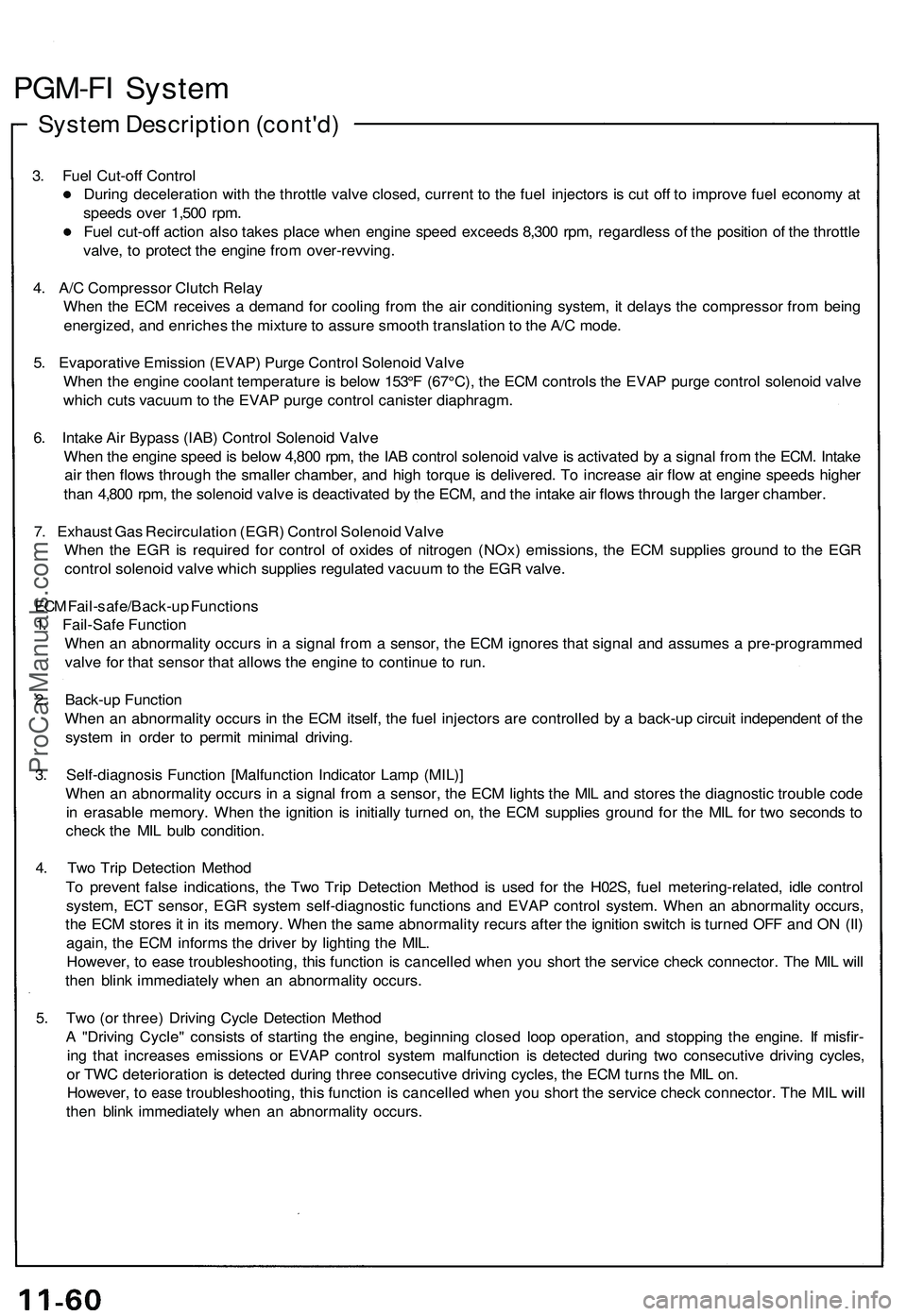
System Description (cont'd)
3. Fuel Cut-off Control
During deceleration with the throttle valve closed, current to the fuel injectors is cut off to improve fuel economy at
speeds over 1,500 rpm.
Fuel cut-off action also takes place when engine speed exceeds 8,300 rpm, regardless of the position of the throttle
valve, to protect the engine from over-revving.
4. A/C Compressor Clutch Relay
When the ECM receives a demand for cooling from the air conditioning system, it delays the compressor from being
energized, and enriches the mixture to assure smooth translation to the A/C mode.
5. Evaporative Emission (EVAP) Purge Control Solenoid Valve
When the engine coolant temperature is below 153°F (67°C), the ECM controls the EVAP purge control solenoid valve
which cuts vacuum to the EVAP purge control canister diaphragm.
6. Intake Air Bypass (IAB) Control Solenoid Valve
When the engine speed is below 4,800 rpm, the IAB control solenoid valve is activated by a signal from the ECM. Intake
air then flows through the smaller chamber, and high torque is delivered. To increase air flow at engine speeds higher
than 4,800 rpm, the solenoid valve is deactivated by the ECM, and the intake air flows through the larger chamber.
7. Exhaust Gas Recirculation (EGR) Control Solenoid Valve
When the EGR is required for control of oxides of nitrogen (NOx) emissions, the ECM supplies ground to the EGR
control solenoid valve which supplies regulated vacuum to the EGR valve.
ECM Fail-safe/Back-up Functions
1. Fail-Safe Function
When an abnormality occurs in a signal from a sensor, the ECM ignores that signal and assumes a pre-programmed
valve for that sensor that allows the engine to continue to run.
2. Back-up Function
When an abnormality occurs in the ECM itself, the fuel injectors are controlled by a back-up circuit independent of the
system in order to permit minimal driving.
3. Self-diagnosis Function [Malfunction Indicator Lamp (MIL)]
When an abnormality occurs in a signal from a sensor, the ECM lights the MIL and stores the diagnostic trouble code
in erasable memory. When the ignition is initially turned on, the ECM supplies ground for the MIL for two seconds to
check the MIL bulb condition.
4. Two Trip Detection Method
To prevent false indications, the Two Trip Detection Method is used for the H02S, fuel metering-related, idle control
system, ECT sensor, EGR system self-diagnostic functions and EVAP control system. When an abnormality occurs,
the ECM stores it in its memory. When the same abnormality recurs after the ignition switch is turned OFF and ON (II)
again, the ECM informs the driver by lighting the MIL.
However, to ease troubleshooting, this function is cancelled when you short the service check connector. The MIL will
then blink immediately when an abnormality occurs.
5. Two (or three) Driving Cycle Detection Method
A "Driving Cycle" consists of starting the engine, beginning closed loop operation, and stopping the engine. If misfir-
ing that increases emissions or EVAP control system malfunction is detected during two consecutive driving cycles,
or TWC deterioration is detected during three consecutive driving cycles, the ECM turns the MIL on.
However,
to
ease
troubleshooting,
this
function
is
cancelled when
you
short
the
service check connector.
The MIL
will
then blink immediately when an abnormality occurs.ProCarManuals.com
Page 1014 of 1503
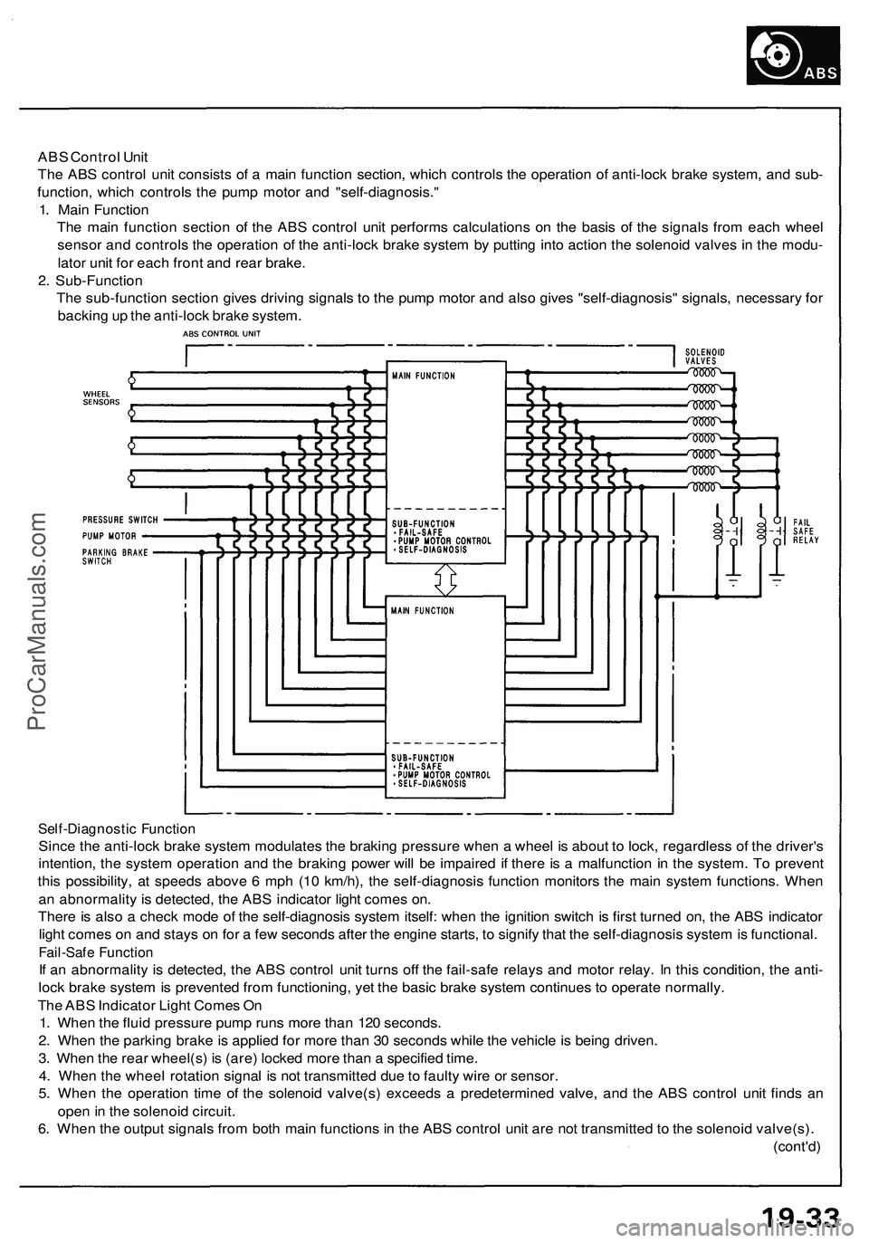
ABS Control Unit
The ABS control unit consists of a main function section, which controls the operation of anti-lock brake system, and sub-
function, which controls the pump motor and "self-diagnosis."
1. Main Function
The main function section of the ABS control unit performs calculations on the basis of the signals from each wheel
sensor and controls the operation of the anti-lock brake system by putting into action the solenoid valves in the modu-
lator unit for each front and rear brake.
2. Sub-Function
The sub-function section gives driving signals to the pump motor and also gives "self-diagnosis" signals, necessary for
backing up the anti-lock brake system.
Self-Diagnostic Function
Since the anti-lock brake system modulates the braking pressure when a wheel is about to lock, regardless of the driver's
intention, the system operation and the braking power will be impaired if there is a malfunction in the system. To prevent
this possibility, at speeds above 6 mph (10 km/h), the self-diagnosis function monitors the main system functions. When
an abnormality is detected, the ABS indicator light comes on.
There is also a check mode of the self-diagnosis system itself: when the ignition switch is first turned on, the ABS indicator
light comes on and stays on for a few seconds after the engine starts, to signify that the self-diagnosis system is functional.
Fail-Safe Function
If an abnormality is detected, the ABS control unit turns off the fail-safe relays and motor relay. In this condition, the anti-
lock brake system is prevented from functioning, yet the basic brake system continues to operate normally.
The ABS Indicator Light Comes On
1. When the fluid pressure pump runs more than 120 seconds.
2. When the parking brake is applied for more than 30 seconds while the vehicle is being driven.
3. When the rear wheel(s) is (are) locked more than a specified time.
4. When the wheel rotation signal is not transmitted due to faulty wire or sensor.
5. When the operation time of the solenoid valve(s) exceeds a predetermined valve, and the ABS control unit finds an
open in the solenoid circuit.
6. When the output signals from both main functions in the ABS control unit are not transmitted to the solenoid valve(s).
(cont'd)ProCarManuals.com
Page 1187 of 1503
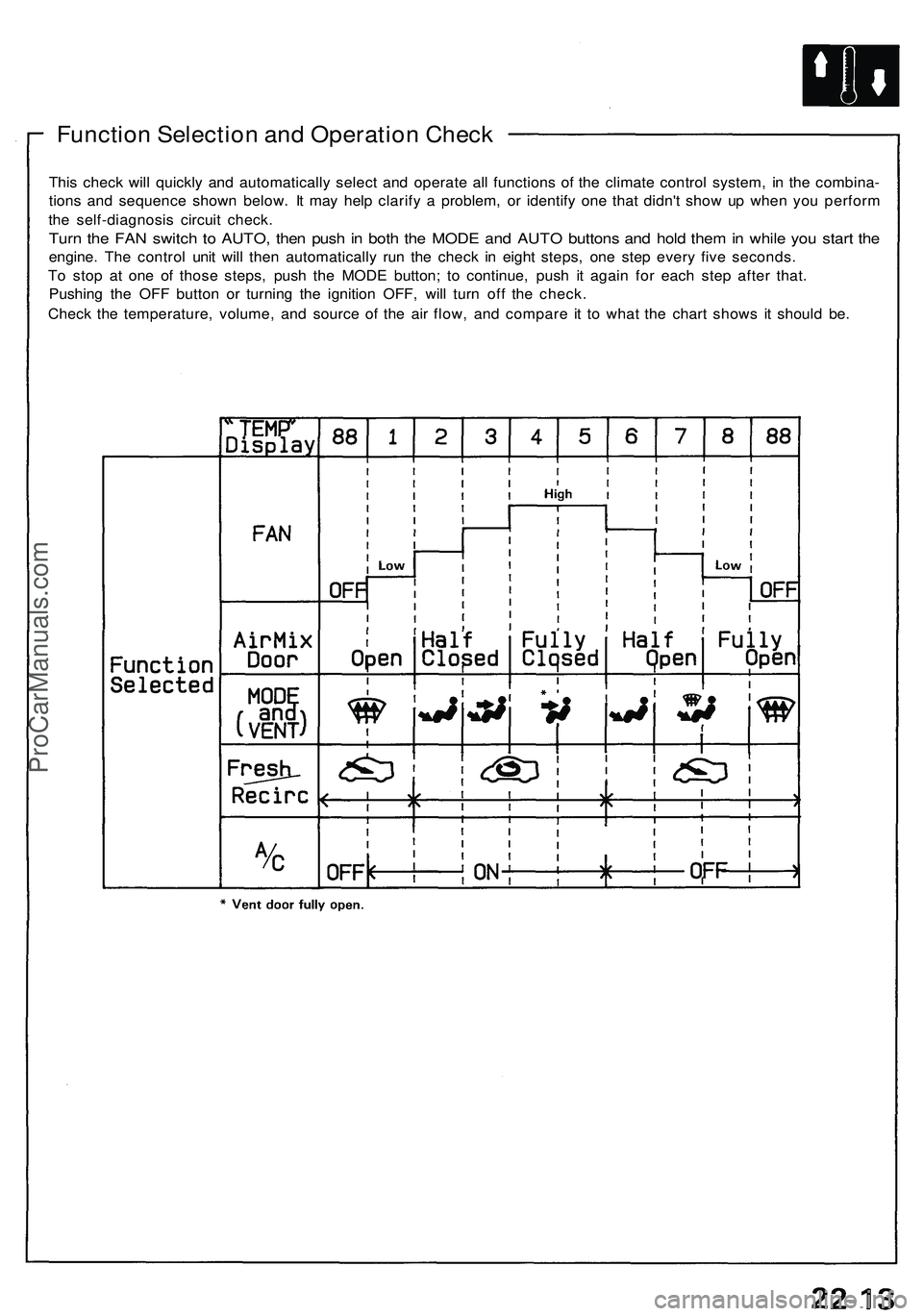
Function Selection and Operation Check
This check will quickly and automatically select and operate all functions of the climate control system, in the combina-
tions and sequence shown below. It may help clarify a problem, or identify one that didn't show up when you perform
the self-diagnosis circuit check.
Turn the FAN switch to AUTO, then push in both the MODE and AUTO buttons and hold them in while you start the
engine. The control unit will then automatically run the check in eight steps, one step every five seconds.
To stop at one of those steps, push the MODE button; to continue, push it again for each step after that.
Pushing the OFF button or turning the ignition OFF, will turn off the check.
Check the temperature, volume, and source of the air flow, and compare it to what the chart shows it should be.ProCarManuals.com
Page 1207 of 1503
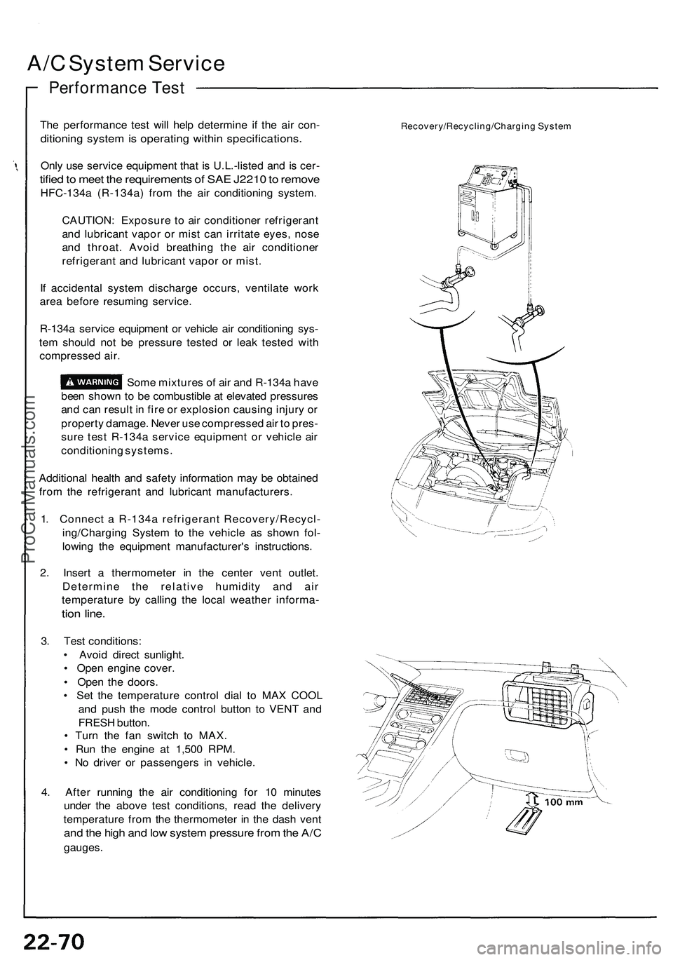
A/C System Service
Performance Test
The performance test will help determine if the air con-
ditioning system is operating within specifications.
Only use service equipment that is U.L.-listed and is cer-
tified to meet the requirements of SAE J2210 to remove
HFC-134a (R-134a) from the air conditioning system.
CAUTION: Exposure to air conditioner refrigerant
and lubricant vapor or mist can irritate eyes, nose
and throat. Avoid breathing the air conditioner
refrigerant and lubricant vapor or mist.
If accidental system discharge occurs, ventilate work
area before resuming service.
R-134a service equipment or vehicle air conditioning sys-
tem should not be pressure tested or leak tested with
compressed air.
Some mixtures of air and R-134a have
been shown to be combustible at elevated pressures
and can result in fire or explosion causing injury or
property damage. Never use compressed air to pres-
sure test R-134a service equipment or vehicle air
conditioning systems.
Additional health and safety information may be obtained
from the refrigerant and lubricant manufacturers.
1. Connect a R-134a refrigerant Recovery/Recycl-
ing/Charging System to the vehicle as shown fol-
lowing the equipment manufacturer's instructions.
2. Insert a thermometer in the center vent outlet.
Determine the relative humidity and air
temperature by calling the local weather informa-
tion line.
3. Test conditions:
• Avoid direct sunlight.
• Open engine cover.
• Open the doors.
• Set the temperature control dial to MAX COOL
and push the mode control button to VENT and
FRESH button.
• Turn the fan switch to MAX.
• Run the engine at 1,500 RPM.
• No driver or passengers in vehicle.
4. After running the air conditioning for 10 minutes
under the above test conditions, read the delivery
temperature from the thermometer in the dash vent
and the high and low system pressure from the A/C
gauges.
Recovery/Recycling/Charging SystemProCarManuals.com
Page 1483 of 1503
Troubleshooting
Self-diagnosis Functio n
The SR S uni t include s a self-diagnosi s function . I f ther e
i s a failur e in th e sensors , SR S unit , inflator , o r thei r cir -
cuits , th e SR S indicato r ligh t i n th e gaug e assembl y
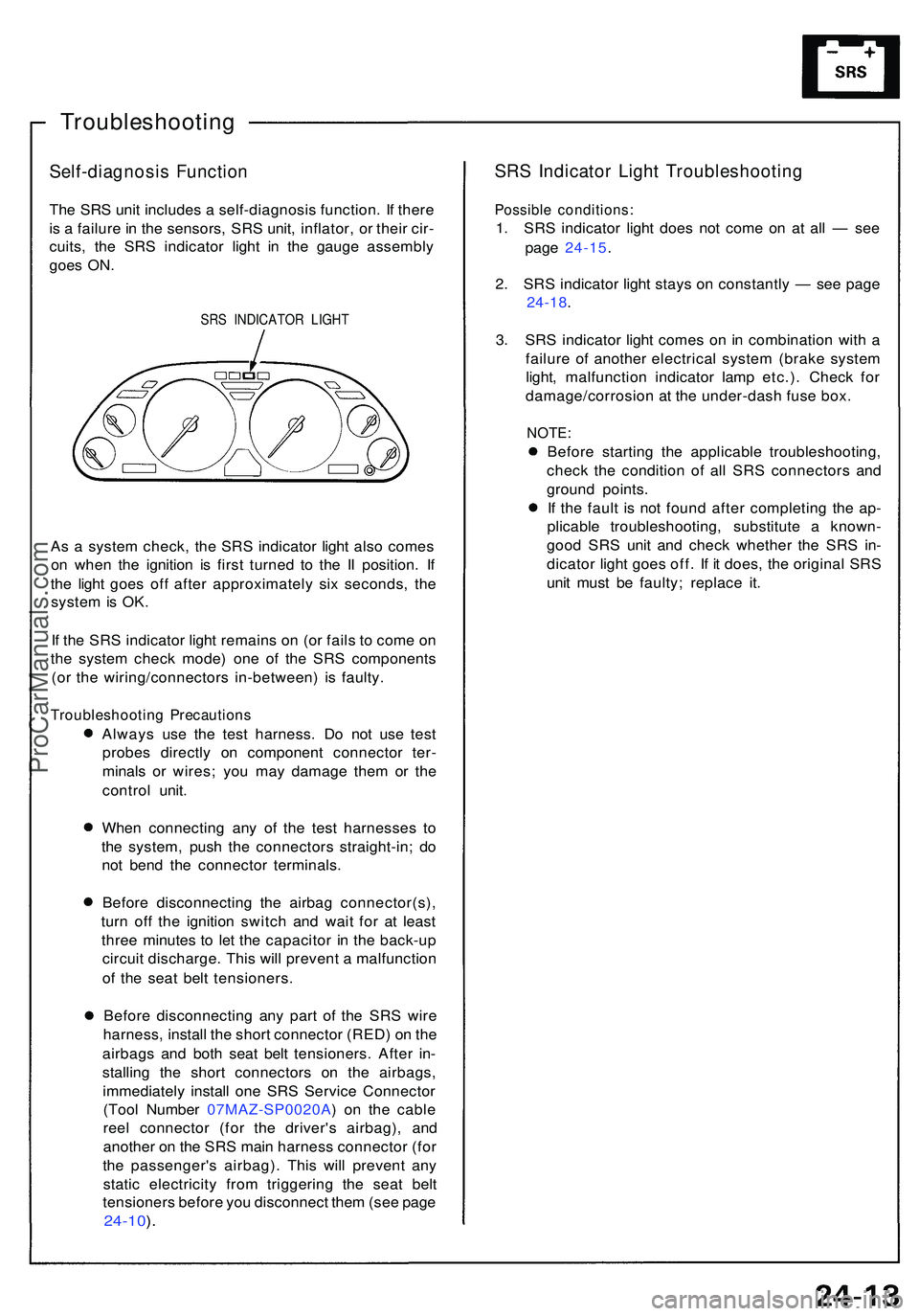
goe s ON .
SRS INDICATO R LIGH T
As a syste m check , th e SR S indicato r ligh t als o come s
o n whe n th e ignitio n i s firs t turne d t o th e I I position . I f
th e ligh t goe s of f afte r approximatel y si x seconds , th e
syste m is OK .
I f th e SR S indicato r ligh t remain s o n (o r fail s t o com e o n
th e syste m chec k mode ) on e o f th e SR S component s
(o r th e wiring/connector s in-between ) i s faulty .
Troubleshootin g Precaution s
Always us e th e tes t harness . D o no t us e tes t
probe s directl y o n componen t connecto r ter -
minal s o r wires ; yo u ma y damag e the m o r th e
contro l unit .
Whe n connectin g an y o f th e tes t harnesse s t o
th e system , pus h th e connector s straight-in ; d o
no t ben d th e connecto r terminals .
Befor e disconnectin g th e airba g connector(s) ,
tur n of f th e ignitio n switc h an d wai t fo r a t leas t
thre e minute s t o le t th e capacito r i n th e back-u p
circui t discharge . Thi s wil l preven t a malfunctio n
o f th e sea t bel t tensioners .
Befor e disconnectin g an y par t o f th e SR S wir e
harness , instal l th e shor t connecto r (RED ) o n th e
airbag s an d bot h sea t bel t tensioners . Afte r in -
stallin g th e shor t connector s o n th e airbags ,
immediatel y instal l on e SR S Servic e Connecto r
(Too l Numbe r 07MAZ-SP0020A ) o n th e cabl e
ree l connecto r (fo r th e driver' s airbag) , an d
anothe r o n th e SR S mai n harnes s connecto r (fo r
th e passenger' s airbag) . Thi s wil l preven t an y
stati c electricit y fro m triggerin g th e sea t bel t
tensioner s befor e yo u disconnec t the m (se e pag e
24-10 ).
SR S Indicato r Ligh t Troubleshootin g
Possible conditions :
1. SR S indicato r ligh t doe s no t com e o n a t al l — se e
pag e 24-15 .
2 . SR S indicato r ligh t stay s o n constantl y — se e pag e
24-18 .
3 . SR S indicato r ligh t come s o n in combinatio n wit h a
failur e o f anothe r electrica l syste m (brak e syste m
light , malfunctio n indicato r lam p etc.) . Chec k fo r
damage/corrosio n a t th e under-das h fus e box .
NOTE :
Before startin g th e applicabl e troubleshooting ,
chec k th e conditio n o f al l SR S connector s an d
groun d points .
I f th e faul t i s no t foun d afte r completin g th e ap -
plicabl e troubleshooting , substitut e a known -
goo d SR S uni t an d chec k whethe r th e SR S in -
dicato r ligh t goe s off . I f i t does , th e origina l SR S
uni t mus t b e faulty ; replac e it .
ProCarManuals.com