Page 188 of 1202
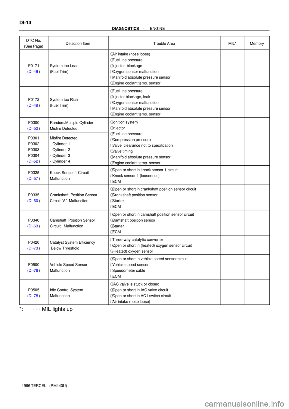
DI-14
- DIAGNOSTICSENGINE
1996 TERCEL (RM440U)DTC No.
(See Page)
Detection ItemTrouble AreaMIL*Memory
P0171
(DI-49)System too Lean
(Fuel Trim)
�Air intake (hose loose)
�Fuel line pressure
�Injector blockage
�Oxygen sensor malfunction
�Manifold absolute pressure sensor
�Engine coolant temp. sensor
��
P0172
(DI-49)System too Rich
(Fuel Trim)
�Fuel line pressure
�Injector blockage, leak
�Oxygen sensor malfunction
�Manifold absolute pressure sensor
�Engine coolant temp. sensor
��
P0300
(DI-52)Random/Multiple Cylinder
Misfire Detected�Ignition system
�Injector
FlliP0301
P0302
P0303
P0304
(DI-52)Misfire Detected
- Cylinder 1
- Cylinder 2
- Cylinder 3
- Cylinder 4�Fuel line pressure
�Compression pressure
�Valve clearance not to specification
�Valve timing
�Manifold absolute pressure sensor
�Engine coolant temp. sensor
��
P0325
(DI-57)Knock Sensor 1 Circuit
Malfunction�Open or short in knock sensor 1 circuit
�Knock sensor 1 (looseness)
�ECM
��
P0335
(DI-60)Crankshaft Position Sensor
Circuit ºAº Malfunction
�Open or short in crankshaft position sensor circuit
�Crankshaft position sensor
�Starter
�ECM
��
P0340
(DI-63)Camshaft Position Sensor
Circuit Malfunction
�Open or short in camshaft position sensor circuit
�Camshaft position sensor
�Starter
�ECM
��
P0420
(DI-73)Catalyst System Efficiency
Below Threshold�Three-way catalytic converter
�Open or short in (heated) oxygen sensor circuit
�(Heated) oxygen sensor
��
P0500
(DI-76)Vehicle Speed Sensor
Malfunction
�Open or short in vehicle speed sensor circuit
�Vehicle speed sensor
�Speedometer cable
�ECM
��
P0505
(DI-78)Idle Control System
Malfunction
�IAC valve is stuck or closed
�Open or short in IAC valve circuit
�Open or short in AC1 switch circuit
�Air intake (hose loose)
��
*: ���� MIL lights up
Page 247 of 1202

FI7081
Waveform of Oxygen Sensor
before CatalystNormal CatalystWaveform of Oxygen
Sensor after Catalyst
- DIAGNOSTICSENGINE
DI-73
1996 TERCEL (RM440U)
DTC P0420 Catalyst System Efficiency Below Threshold
CIRCUIT DESCRIPTION
The ECM compares the waveform of the oxygen sensor located before the catalyst with the waveform of
the oxygen sensor located after the catalyst to determine whether or not catalyst performance has deterio-
rated.
Air-fuel ratio feedback compensation keeps the waveform of the oxygen sensor before the catalyst repeat-
edly changing back and forth from rich to lean.
If the catalyst is functioning normally, the waveform of the oxygen sensor after the catalyst switches back
and forth between rich and lean much more slowly than the waveform of the oxygen sensor before the cata-
lyst.
But when both waveforms change at a similar rate, it indicates that catalyst performance has deteriorated.
DTC No.DTC Detection ConditionTrouble Area
P0420
After the engine and the catalyst are warmed up, and while
vehicle is driven within the set vehicle and engine speed
range, the waveforms of the oxygen sensor (bank 1 sensor 1)
and heated oxygen sensor (bank 1 sensor 2) have the same
amplitude (2 trip detection logic)
�Three-way catalytic converter
�Open or short in (heated) oxygen sensor circuit
�(Heated) oxygen sensor
DI1EE-18
Page 248 of 1202

FI7132
Engine Speed
2,500 - 3,000 rpm
Idling
IG SW OFF
Warmed up3 min. or soCheckTime (a)(c)
(d)
(b)
FI6514
OX Signal Waveform (Oscilloscope)
1.0 V
0 V
200 m sec. /Division
DI-74
- DIAGNOSTICSENGINE
1996 TERCEL (RM440U)
CONFIRMATION ENGINE RACING PATTERN
(a) Connect the TOYOTA hand-held tester to the DLC3, or connect the probe of the oscilloscope between
terminals OX1, OX2 and E1 of ECM.
(b) Start engine and warm it up with all accessories switched OFF until engine coolant temperature is
stable.
(c) Race the engine at 2,500 - 3,000 rpm for about 3 minutes.
(d) After confirming that the waveform of the oxygen sensor, bank 1 sensor 1 (OX1), oscillate around 0.5
V during feedback to the ECM, check the waveform of the heated oxygen sensor, bank 1 sensor 2
(OX2).
HINT:
If there is a malfunction in the system, the waveform of the
heated oxygen sensor, bank 1 sensor 2 (OX2), is almost the
same as that of the oxygen sensor, bank 1 sensor 1 (OX1), on
the left.
There are some cases where, even though a malfunction ex-
ists, the MIL may either light up or not light up.
INSPECTION PROCEDURE
1 Are there any other codes (besides DTC P0420) being output?
YES Go to relevant DTC chart.
NO
2 Check heated oxygen sensor (bank 1 sensor 2) (See page DI-44).
Page 685 of 1202
Z19162
Type A
Z14812
Type B
P04209
SST(A)
Turn SST(B)
P04210
SST (C)
CH-8
- CHARGINGGENERATOR
1996 TERCEL (RM440U)
3. Type A
REMOVE RECTIFIER HOLDER
(a) Remove the 4 screws and rectifier holder.
(b) Remove the 4 rubber insulators.
4. Type B:
REMOVE RECTIFIER HOLDER
(a) Remove the 4 screws.
(b) Using needle-nose pliers, straighten the stator lead wire.
(c) Remove the rectifier holder.
5. REMOVE PULLEY
(a) Hold SST (A) with a torque wrench, and tighten SST (B)
clockwise to the specified torque.
SST 09820-63010
Torque: 39 N´m (400 kgf´cm, 29 ft´lbf)
(b) Check that SST (A) is secured to the rotor shaft.
(c) Mount SST (C) in a vise.
(d) Insert SST (B) into SST (C), and attach the pulley nut to
SST (C).
Page 692 of 1202

CH0HC-01
P04218
P13695
29 mm
Socket
Wrench
P04209
SST (A)
Turn SST (B)
P04210
SST (C)
- CHARGINGGENERATOR
CH-15
1996 TERCEL (RM440U)
REASSEMBLY
1. PLACE RECTIFIER END FRAME ON PULLEY
2. INSTALL ROTOR TO DRIVE END FRAME
3. INSTALL RECTIFIER END FRAME
(a) Install the generator washer to the rectifier end frame.
NOTICE:
Be careful of the generator washer installation direction.
(b) Using a 29 mm socket wrench and press, slowly press in
the rectifier end frame.
(c) Type A
Install the 4 nuts.
Torque: 4.5 N´m (46 kgf´cm, 40 in.´lbf)
(d) Type B:
Install the 2 nuts and 2 bolts.
Torque: 4.5 N´m (46 kgf´cm, 40 in.´lbf)
4. INSTALL PULLEY
(a) Install the pulley to the rotor shaft by tightening the pulley
nut by hand.
(b) Hold SST (A) with a torque wrench, and tighten SST (B)
clockwise to the specified torque.
SST 09820-63010
Torque: 39 N´m (400 kgf´cm, 29 ft´lbf)
(c) Check that SST (A) is secured to the pulley shaft.
(d) Mount SST (C) in a vise.
(e) Insert SST (B) into SST (C), and attach the pulley nut to
SST (C).