Page 363 of 1202

AB0117 AB0118 AB0119
R12658H00032
LOCK
ACC
ON
or
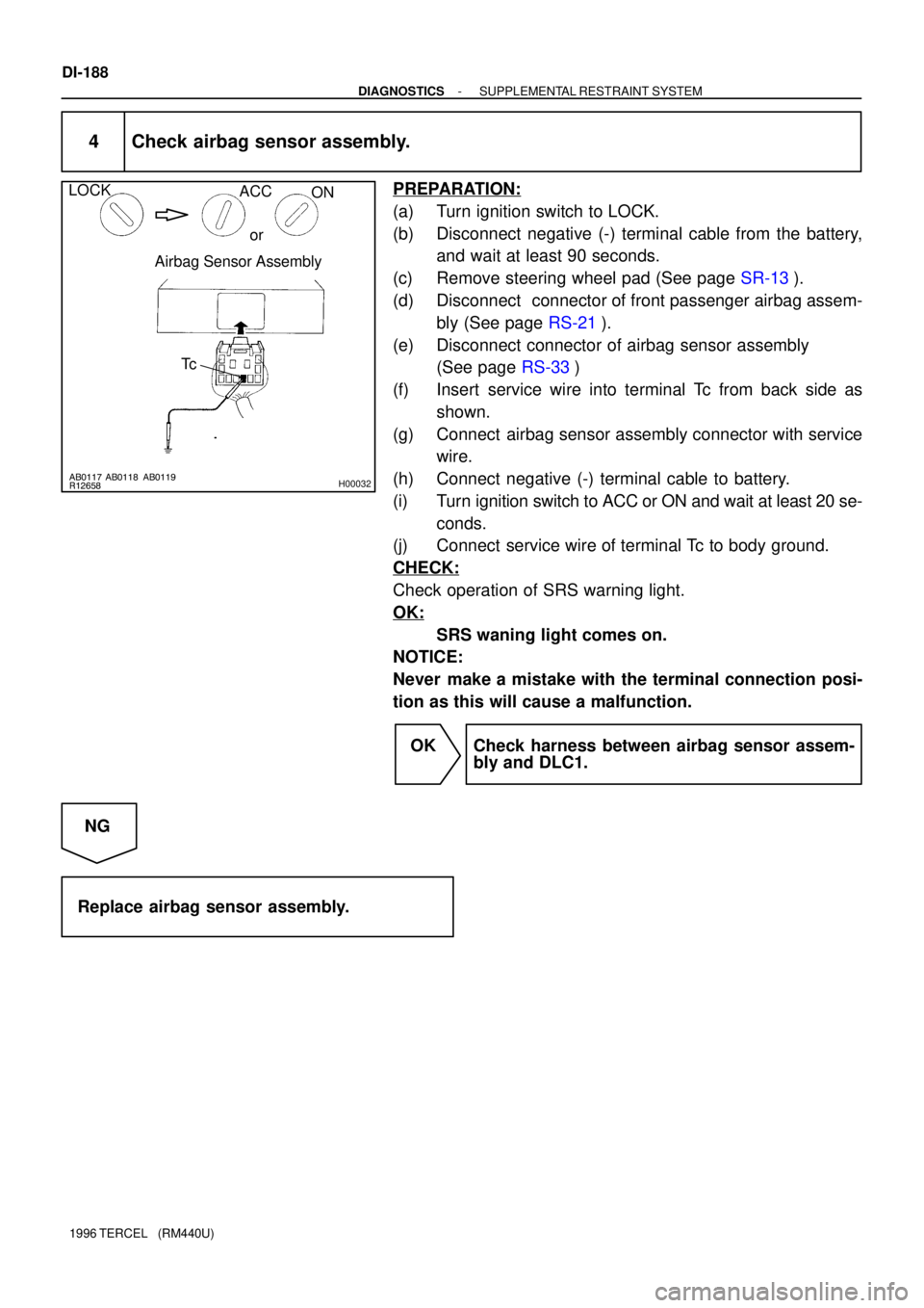
Airbag Sensor Assembly
Tc
DI-188
- DIAGNOSTICSSUPPLEMENTAL RESTRAINT SYSTEM
1996 TERCEL (RM440U)
4 Check airbag sensor assembly.
PREPARATION:
(a) Turn ignition switch to LOCK.
(b) Disconnect negative (-) terminal cable from the battery,
and wait at least 90 seconds.
(c) Remove steering wheel pad (See page SR-13).
(d) Disconnect connector of front passenger airbag assem-
bly (See page RS-21).
(e) Disconnect connector of airbag sensor assembly
(See page RS-33)
(f) Insert service wire into terminal Tc from back side as
shown.
(g) Connect airbag sensor assembly connector with service
wire.
(h) Connect negative (-) terminal cable to battery.
(i) Turn ignition switch to ACC or ON and wait at least 20 se-
conds.
(j) Connect service wire of terminal Tc to body ground.
CHECK:
Check operation of SRS warning light.
OK:
SRS waning light comes on.
NOTICE:
Never make a mistake with the terminal connection posi-
tion as this will cause a malfunction.
OK Check harness between airbag sensor assem-
bly and DLC1.
NG
Replace airbag sensor assembly.
Page 818 of 1202

SA10Z-04
- SUSPENSION AND AXLETROUBLESHOOTING
SA-1
817 Author�: Date�:
1996 TERCEL (RM440U)
TROUBLESHOOTING
PROBLEM SYMPTOMS TABLE
Use the table to help you find the cause of the problem. The numbers indicate the priority of the likely case
of the problem. Check each part in order. If necessary, replace these parts.
SymptomSuspect AreaSee page
Wander/pulls
1. Tire (Worn or improperly inflated)
2. Wheel alignment (Incorrect)
3. Steering linkage (Loosen or worn)
4. Hub bearings (Worn)
5. Steering gear (Out of adjustment or broken)
6. Suspension parts (Worn)SA-2
SA-4
SA-8
-
SA-10
SA-39
SR-34
SR-46
-
Bottoming
1. Vehicle (Overloaded)
2. Spring (Weak)
3. Shock absorber (Worn)-
SA-24
SA-44
SA-24
SA-44
Sways/pitches
1. Tire (Worn or improperly inflated)
2. Stabilizer bar (Rear axle beam)
3. Shock absorber (Worn)SA-2
SA-54
SA-24
SA-44
Front wheel shimmy
1. Tire (Worn or improperly inflated)
2. Wheels (Out of balance)
3. Shock absorber (Worn)
4. Wheel alignment (Incorrect)
5. Ball joint (Worn)
6. Hub bearing (Worn)
7. Steering linkage (Loosen or worn)
8. Steering gear (Out of adjustment or broken)SA-2
SA-2
SA-24
SA-4
SA-34
SA-10
-
SR-34
SR-46
Abnormal tire wear
1. Tire (Worn or improperly inflated)
2. Wheel alignment (Incorrect)
3. Suspension parts (Worn)
4. Shock absorber (Worn)SA-2
SA-4
SA-8
-
SA-24
SA-44
Page 820 of 1202
R11682
- SUSPENSION AND AXLETIRE AND WHEEL
SA-3
819 Author�: Date�:
1996 TERCEL (RM440U)
4. CHECK WHEEL BEARING LOOSENESS
(a) Check the backlash in bearing shaft direction.
Maximum: 0.05 mm (0.0020 in.)
(b) Check the axle hub deviation.
Maximum: 0.05 mm (0.0020 in.)
5. CHECK FRONT SUSPENSION FOR LOOSENESS
6. CHECK STEERING LINKAGE FOR LOOSENESS
7. CHECK BALL JOINT FOR LOOSENESS
8. CHECK SHOCK ABSORBER WORKS PROPERLY
�Check for oil leaks
�Check mounting bushings for wear
�Bounce front and rear of the vehicle
Page 821 of 1202

R11681R11753F02280
Front
RearSA23E-01
Z03382
SA3213
AB
C D
Front SA-4
- SUSPENSION AND AXLEFRONT WHEEL ALIGNMENT
820 Author�: Date�:
1996 TERCEL (RM440U)
FRONT WHEEL ALIGNMENT
INSPECTION
1. MEASURE VEHICLE HEIGHT
Tire sizeFrontRear
155SR13187.9 mm (7.40 in.)253.2 mm (9.97 in.)
Front measuring point:
Measure from the ground to the center of the lower suspension
arm front mounting bolt.
Rear measuring point:
Measure from the ground to the center of the axle beam mount-
ing bolt.
NOTICE:
Before inspecting the wheel alignment, adjust the vehicle
height to the specification.
If the vehicle height is not the specification, try to adjust it by
pushing down on or lifting the body.
2. INSTALL CAMBER-CASTER-KINGPIN GAUGE OR
ONTO WHEEL ALIGNMENT TESTER
Follow the specific instruction of the equipment manufacturer.
3. INSPECT CAMBER, CASTER AND STEERING AXIS
INCLINATION
Camber
Left-right error-0°20' ± 45'
45' (0.75°) or less
Caster
Left-right error1°20' ± 45
45' (0.75°) or less
Steering axis inclination
Left-right error12°10' ± 45'
45' (0.75°) or less
HINT:
If the caster and steering axis inclination are not within the spec-
ification, after the camber has been correctly adjusted, recheck
the suspension parts for damaged and/or worn out parts.
4. INSPECT TOE-IN
Toe-in
(total)A + B: 0.1° ± 0.2°
C - D: 1 ± 2 mm (0.04 ± 0.08 in.)
If the toe-in is not within the specification, adjust by the tie rod
end.
Page 824 of 1202
SA0028
A: Inside
B: Outside AB
Front BA
- SUSPENSION AND AXLEFRONT WHEEL ALIGNMENT
SA-7
823 Author�: Date�:
1996 TERCEL (RM440U)
7. INSPECT WHEEL ANGLE
Turn the steering wheel fully, and measure the turning angle.
Inside wheel35°55' ± 2°
Reference: Outside wheel32°10'
If the wheel angles differ from the standard specifications, in-
spect the toe-in.
Page 827 of 1202

SA114-03
R11682
F03986
F03987
SA-10
- SUSPENSION AND AXLEFRONT AXLE HUB
1996 TERCEL (RM440U)
REMOVAL
1. REMOVE FRONT WHEEL
Torque: 103 N´m (1,050 kgf´cm, 76 ft´lbf)
2. w/ ABS
REMOVE BOLT AND ABS SPEED SENSOR
Torque: 7.8 N´m (80 kgf´cm, 69 in.´lbf)
3. REMOVE FRONT BRAKE CALIPER AND DISC
(a) Remove the 2 bolts and brake caliper from the steering
knuckle.
Torque: 88 N´m (900 kgf´cm, 65 in.´lbf)
(b) Support the brake caliper securely.
(c) Remove the disc.
4. CHECK BACKLASH IN BEARING SHAFT DIRECTION
Using a dial indicator, check the backlash near the center of the
axle hub, and check the backlash in the bearing shaft direction.
Maximum: 0.05 mm (0.0020 in.)
If the backlash exceeds the maximum, replace the bearing.
5. CHECK AXLE HUB DEVIATION
Using a dial indicator, check the deviation at the surface of the
axle hub outside the hub bolt.
Maximum: 0.05 mm (0.0020 in.)
If the deviation exceeds the maximum, replace the axle hub.
6. REMOVE DRIVE SHAFT LOCK NUT
(a) Install the brake disc and caliper.
(b) Remove the cotter pin and lock cap.
(c) With applying the brakes, remove the nut.
Torque: 216 N´m (2,200 kgf´cm, 159 ft´lbf)
(d) Remove the brake caliper and disc.
7. LOOSEN 2 NUTS ON LOWER SIDE OF SHOCK AB-
SORBER
Torque: 245 N´m (2,500 kgf´cm, 181 ft´lbf)
HINT:
�Do not remove the 2 bolts.
�Coat the nut's thread with engine oil.
Page 835 of 1202

SA128-02
FA1535
SST
F03986
SA-18
- SUSPENSION AND AXLEFRONT DRIVE SHAFT
1996 TERCEL (RM440U)
REMOVAL
NOTICE:
�The hub bearing could be damaged if it is subjected
to the vehicle weight, such as when moving the ve-
hicle with the drive shaft removed. Therefore, if it is
absolutely necessary to place the vehicle weight on
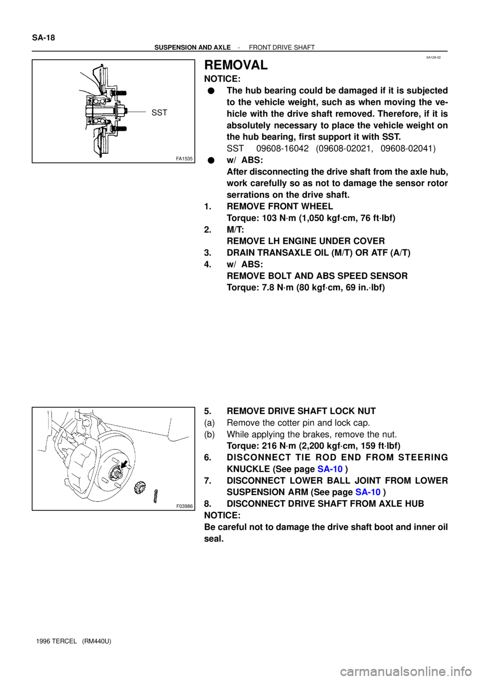
the hub bearing, first support it with SST.
SST 09608-16042 (09608-02021, 09608-02041)
�w/ ABS:
After disconnecting the drive shaft from the axle hub,
work carefully so as not to damage the sensor rotor
serrations on the drive shaft.
1. REMOVE FRONT WHEEL
Torque: 103 N´m (1,050 kgf´cm, 76 ft´lbf)
2. M/T:
REMOVE LH ENGINE UNDER COVER
3. DRAIN TRANSAXLE OIL (M/T) OR ATF (A/T)
4. w/ ABS:
REMOVE BOLT AND ABS SPEED SENSOR
Torque: 7.8 N´m (80 kgf´cm, 69 in.´lbf)
5. REMOVE DRIVE SHAFT LOCK NUT
(a) Remove the cotter pin and lock cap.
(b) While applying the brakes, remove the nut.
Torque: 216 N´m (2,200 kgf´cm, 159 ft´lbf)
6. DISCONNECT TIE ROD END FROM STEERING
KNUCKLE (See page SA-10)
7. DISCONNECT LOWER BALL JOINT FROM LOWER
SUSPENSION ARM (See page SA-10)
8. DISCONNECT DRIVE SHAFT FROM AXLE HUB
NOTICE:
Be careful not to damage the drive shaft boot and inner oil
seal.
Page 842 of 1202
SA1W8-02
- SUSPENSION AND AXLEFRONT SHOCK ABSORBER
SA-25
1996 TERCEL (RM440U)
REMOVAL
1. REMOVE FRONT WHEEL
Torque: 103 N´m (1,050 kgf´cm, 76 ft´lbf)
2. REMOVE FLEXIBLE HOSE
Remove the bolt and disconnect the flexible hose from the shock absorber.
Torque: 29 N´m (300 kgf´cm, 22 ft´lbf)
3. w/ ABS:
DISCONNECT ABS SPEED SENSOR WIRE HARNESS
Remove the bolt and disconnect the ABS speed sensor wire harness from the shock absorber.
Torque: 5.4 N´m (55 kgf´cm, 48 in.´lbf)
4. DISCONNECT SHOCK ABSORBER FROM STEERING KNUCKLE
Remove the 2 nuts and bolts and disconnect the shock absorber from steering knuckle,
Torque: 245 N´m (2,500 kgf´cm, 181 ft´lbf)
HINT:
Coat the nut's threads with engine oil.
5. REMOVE SHOCK ABSORBER AND COIL SPRING
(a) Remove the 3/4 nuts on the upper side of the shock absorber.
Torque: 39 N´m (400 kgf´cm, 29 ft´lbf)
(b) Remove the shock absorber with the coil spring.