Page 1008 of 1202

- BODY ELECTRICALBODY ELECTRICAL SYSTEM
BE-7
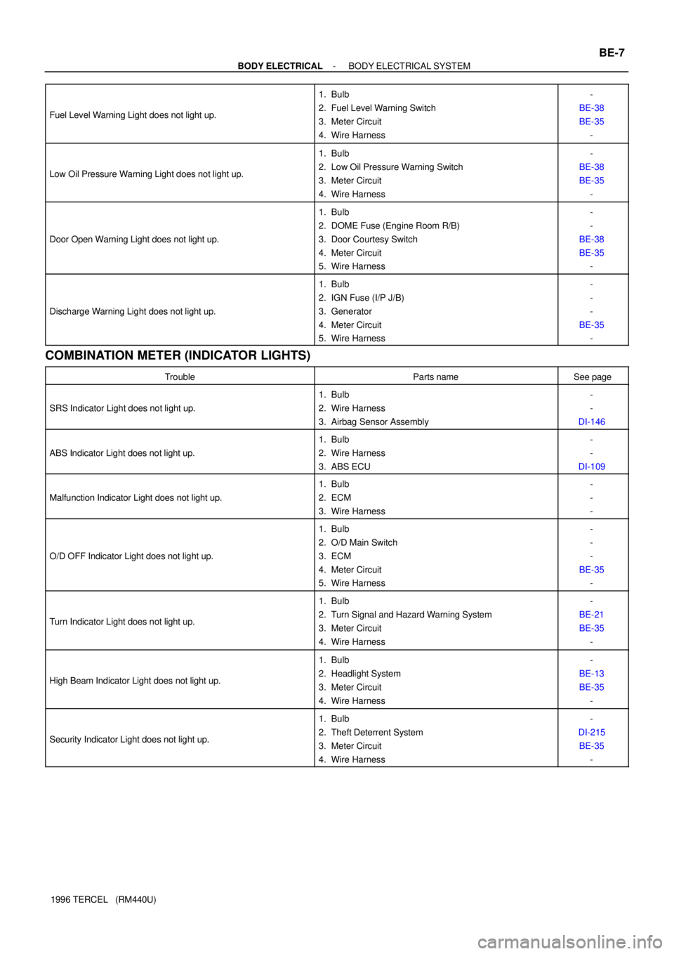
1996 TERCEL (RM440U) Fuel Level Warning Light does not light up.
1. Bulb
2. Fuel Level Warning Switch
3. Meter Circuit
4. Wire Harness-
BE-38
BE-35
-
Low Oil Pressure Warning Light does not light up.
1. Bulb
2. Low Oil Pressure Warning Switch
3. Meter Circuit
4. Wire Harness-
BE-38
BE-35
-
Door Open Warning Light does not light up.
1. Bulb
2. DOME Fuse (Engine Room R/B)
3. Door Courtesy Switch
4. Meter Circuit
5. Wire Harness-
-
BE-38
BE-35
-
Discharge Warning Light does not light up.
1. Bulb
2. IGN Fuse (I/P J/B)
3. Generator
4. Meter Circuit
5. Wire Harness-
-
-
BE-35
-
COMBINATION METER (INDICATOR LIGHTS)
TroubleParts nameSee page
SRS Indicator Light does not light up.
1. Bulb
2. Wire Harness
3. Airbag Sensor Assembly-
-
DI-146
ABS Indicator Light does not light up.
1. Bulb
2. Wire Harness
3. ABS ECU-
-
DI-109
Malfunction Indicator Light does not light up.
1. Bulb
2. ECM
3. Wire Harness-
-
-
O/D OFF Indicator Light does not light up.
1. Bulb
2. O/D Main Switch
3. ECM
4. Meter Circuit
5. Wire Harness-
-
-
BE-35
-
Turn Indicator Light does not light up.
1. Bulb
2. Turn Signal and Hazard Warning System
3. Meter Circuit
4. Wire Harness-
BE-21
BE-35
-
High Beam Indicator Light does not light up.
1. Bulb
2. Headlight System
3. Meter Circuit
4. Wire Harness-
BE-13
BE-35
-
Security Indicator Light does not light up.
1. Bulb
2. Theft Deterrent System
3. Meter Circuit
4. Wire Harness-
DI-215
BE-35
-
Page 1010 of 1202
BE0QR-01
I05952
Engine Room R/B
R/B No.5 (CANADA models)
I/P J/BR/B No.7
- BODY ELECTRICALPOWER SOURCE
BE-9
1031 Author�: Date�:
1996 TERCEL (RM440U)
POWER SOURCE
LOCATION
Page 1014 of 1202
BE0QU-01
I05914
D.R.L. : Daytime Running Light
* : CANADA Models OnlyEngine Room R/B
� Headlight Control Relay
� HEAD LH Fuse
� HEAD RH Fuse
� DOME Fuse
� DIM M-Fuse
� DRL Fuse
R/B No.5
� D.R.L No.4 Relay
� Headlight Dimmer Relay
� HEAD LH-UPR Fuse
� HEAD RH-UPR Fuse
� HEAD LH-LWR Fuse
� HEAD RH-LWR Fuse *
*
Combination Switch
� Lignt Control Switch
� Headlight Dimmer Switch*
* D.R.L. Main Relay
Door Courtesy Switch
Taillights I/P J/B
� Integration Relay
� Taillight Control Relay
� TAIL Fuse
� ECU-IG FuseHeadlights
- BODY ELECTRICALHEADLIGHT AND TAILLIGHT SYSTEM
BE-13
1035 Author�: Date�:
1996 TERCEL (RM440U)
HEADLIGHT AND TAILLIGHT SYSTEM
LOCATION
Page 1018 of 1202

Z08448
Wire Harness Side
- BODY ELECTRICALHEADLIGHT AND TAILLIGHT SYSTEM
BE-17
1996 TERCEL (RM440U)
6. INSPECT D.R.L. MAIN RELAY CIRCUIT
(a) Disconnect the connector from relay and inspect the con-
nector on wire harness side, as shown.
Tester connectionConditionSpecified condition
7 - GroundHeadlight dimmer switch Low beam or High
beam No continuity
7 - GroundHeadlight dimmer switch Flash Continuity
8 - GroundParking brake switch OFF
(Switch pin pushed in)No continuity
8 - GroundParking brake switch ON
(Switch pin released)Continuity
12 - GroundConstantContinuity
13 - GroundConstantContinuity
16 - GroundHeadlight dimmer switch Low beam No continuity
16 - GroundHeadlight dimmer switch High beam or Flash Continuity
2 - Ground
18 - GroundIgnition switch LOCK or ACCNo voltage
2 - Ground
18 - GroundIgnition switch ONBattery positive voltage
4 - GroundConstantBattery positive voltage
6 - GroundConstantBattery positive voltage
10 - GroundConstantBattery positive voltage
11 - GroundEngine StopNo voltage
11 - GroundEngine RunningBattery positive voltage
15 - GroundConstantBattery positive voltage
If circuit is as specified, try replacing the relay with a new one.
If the circuit is not as specified, inspect the circuit connected to
other parts.
Page 1022 of 1202
BE0R0-01
I05915
Engine Room R/B
� HAZ-HORN Fuse
Hazard Warning Switch
Turn Signal and Hazard Warning Lights
Turn Signal Flasher
Turn Signal Switch
Ignition Switch
Turn Signal and Hazard Warning Lights I/P J/B
� TURN Fuse
- BODY ELECTRICALTURN SIGNAL AND HAZARD WARNING SYSTEM
BE-21
1043 Author�: Date�:
1996 TERCEL (RM440U)
TURN SIGNAL AND HAZARD WARNING SYSTEM
LOCATION
Page 1024 of 1202
BE0R2-01
I05916
Door Courtesy SwitchesRoom Light SwitchR/B No.5 Engine Room R/B
� DOME Fuse
Door Courtesy Switches
- BODY ELECTRICALINTERIOR LIGHT SYSTEM
BE-23
1045 Author�: Date�:
1996 TERCEL (RM440U)
INTERIOR LIGHT SYSTEM
LOCATION
Page 1033 of 1202

BE26P-01
BE-32
- BODY ELECTRICALCOMBINATION METER
1054 Author�: Date�:
1996 TERCEL (RM440U)
COMBINATION METER
ON-VEHICLE INSPECTION
1. INSPECT SPEEDOMETER ON-VEHICLE
Using a speedometer tester, inspect the speedometer for allowable indication error and check the operation
of the odometer.
HINT:
Tire wear and tire over or under inflation will increase the indication error.
If error is excessive, replace the speedometer.
USA (mph)CANADA (km/h)
Standard indication Allowable rangeStandard indication Allowable range
20 18 - 24 20 16 - 26
40 38 - 45 40 38 - 48
60 59 - 67 60 56 - 69
80 79 - 88 80 76 - 90
100 100 - 110 100 96 - 110
120 114 - 131
140 134 - 152
160 152 - 174
2. INSPECT TACHOMETER
(a) Connect a tune-up test tachometer, and start the engine.
NOTICE:
Reversing the connection of the tachometer will damage the transistors and diodes inside. When re-
moving or installing the tachometer, be careful not to drop or subject it to heavy shocks.
(b) Compare the tester and tachometer indications.
DC 13.5 V 25°C (68°F)
Standard indication (rpm)Allowable range (rpm)
700610 - 750
3,0002,850 - 3,150
5,0004,850 - 5,150
7,0006,790 - 7,210
If error is excessive, replace the tachometer.
Page 1034 of 1202
BE0RA-02
I05953
Combination Meter
� Meter CircuitDoor Lock Control Relay or Theft Deterrent ECU
ECM
Ignition Switch Rheostat Light Control Volume
ABS ECUBrake Fluid Level Warning Switch
Engine Room R/B
� DOME Fuse
I/P J/B
� Integration Relay
� GAUGE Fuse
� IGN Fuse
� TURN Fuse
� TAIL FuseAirbag Sensor Assembly
Parking Brake Switch
- BODY ELECTRICALCOMBINATION METER
BE-33
1996 TERCEL (RM440U)
LOCATION