Page 416 of 1202
N12895
BG BH
W-B W-B 1Luggage Compartment
Door Key Lock and Unlock SwitchL4
2
LIE29
LT49
LUG Theft Deterrent ECU
- DIAGNOSTICSTHEFT DETERRENT SYSTEM
DI-241
1996 TERCEL (RM440U)
Luggage Compartment Door Key Lock and Unlock Switch
Circuit
CIRCUIT DESCRIPTION
The luggage compartment door key lock and unlock switch goes on when the luggage compartment door
key cylinder is turned to the unlock side with the key.
WIRING DIAGRAM
DI4NC-01
Page 417 of 1202

(-)
1
Connect
I05899BE4061
I09783
21
Disconnect
DI-242
- DIAGNOSTICSTHEFT DETERRENT SYSTEM
1996 TERCEL (RM440U)
INSPECTION PROCEDURE
1 Check voltage between terminal 1 of l")
BE4061I05898I09782
ON
(+)
(-)
1
Connect
I05899BE4061
I09783
21
Disconnect
DI-242
- DIAGNOSTICSTHEFT DETERRENT SYSTEM
1996 TERCEL (RM440U)
INSPECTION PROCEDURE
1 Check voltage between terminal 1 of luggage compartment door key lock and
unlock switch connector and body ground.
PREPARATION:
(a) Remove luggage compartment door trim.
(b) Turn ignition switch ON.
CHECK:
Measure voltage between terminal 1 of luggage compartment
door key lock and unlock switch connector and body ground,
when the key is turned to the unlock side and not turned.
OK:
Key operationVoltage
Turned to the unlock side0 V
Not turnedBattery positive voltage
OK Check and replace theft deterrent ECU.*1
NG
2 Check luggage compartment door key lock and unlock switch.
PREPARATION:
Disconnect luggage compartment door key lock and unlock
switch connector.
CHECK:
Check continuity between terminals 1 and 2, when the key is
turned to the unlock side and not turned.
OK:
Key operationTester connectionSpecified condition
Turned to unlock side1 - 2Continuity
Not turned-No continuity
NG Repair or replace luggage compartment door
key lock and unlock switch.
OK
Page 439 of 1202

INSTALLATION
1. INSTALL CRANKSHAFT TIMING PULLEY
(a) Align")
EM1OE-01
P20743
P20742
P20744
P20390SST
P20915
Timing Mark
SST
Installation
Mark
- ENGINE MECHANICALTIMING BELT
EM-17
1996 TERCEL (RM440U)
INSTALLATION
1. INSTALL CRANKSHAFT TIMING PULLEY
(a) Align the pulley set key with the key groove of the pulley.
(b) Slide on the timing pulley, facing the rotor side of the
crankshaft position sensor inward.
2. TEMPORARILY INSTALL NO.1 IDLER PULLEY AND
TENSION SPRING
(a) Install the tension spring to the idler pulley.
(b) Align the bracket pin hole with the pivot pin.
(c) Install the idler pulley with the bolt. Do not tighten the bolt
yet.
(d) Pry the idler pulley toward the left as far as it will go and
temporarily tighten the bolt.
(e) Check that the idler pulley moves smoothly.
3. INSTALL NO.2 IDLER PULLEY
(a) Install the idler pulley with the bolt.
Torque: 28 N´m (280 kgf´cm, 20 ft´lbf)
(b) Check that the idler pulley moves smoothly.
4. INSTALL CAMSHAFT TIMING PULLEY
(a) Align the camshaft knock pin with the knock pin groove on
the pulley side with the 5E mark, and slide on the timing
pulley.
(b) Using SST, install the pulley bolt.
SST 09960-10010 (09962-01000, 09963-01000)
Torque: 51 N´m (510 kgf´cm, 37 ft´lbf)
5. SET NO.1 CYLINDER TO TDC/COMPRESSION
(a) Using SST, align the hole of the camshaft timing pulley on
the side with the 5E mark with the timing mark of the bear-
ing cap.
SST 09960-10010 (09962-01000, 09963-01000)
Page 441 of 1202
P21439
2 Revolutions
P20537
Timing Mark
P20552
P20745
P20157
SST
- ENGINE MECHANICALTIMING BELT
EM-19
1996 TERCEL (RM440U)
(b) Slowly turn the crankshaft pulley 2 revolutions from TDC
to TDC.
NOTICE:
Always turn the crankshaft clockwise.
(c) Check that each pulley aligns with the timing marks as
shown in the illustration.
If the timing marks do not align, remove the timing belt and rein-
stall it.
(d) Tighten the No.1 idler pulley bolt.
Torque: 18.5 N´m (185 kgf´cm, 13 ft´lbf)
(e) Remove the crankshaft pulley bolt.
8. INSTALL TIMING BELT GUIDE
Install the guide, facing the cup side outward.
9. INSTALL NO.1 TIMING BELT COVER
(a) Install the gasket to the belt cover.
(b) Install the belt cover with the 3 bolts.
10. INSTALL NO.3 TIMING BELT COVER
11. INSTALL CRANKSHAFT PULLEY
(a) Align the pulley set key with the key groove of the pulley,
and slide on the pulley.
(b) Using SST, install the pulley bolt.
SST 09213-14010, 09330-00021
Torque: 155 N´m (1,550 kgf´cm, 112 ft´lbf)
Page 715 of 1202
MX07D-03
MX-2
- MANUAL TRANSAXLETROUBLESHOOTING
714 Author�: Date�:
1996 TERCEL (RM440U)
TROUBLESHOOTING
PROBLEM SYMPTOMS TABLE
Use the table below to help you find the cause of the problem. The numbers indicate the priority of the likely
cause of the problem. Check each part in order. If necessary, replace these parts.
SymptomSuspect AreaSee page
Noise
15.Oil (Level low)
16.Oil (Wrong)
17.Gear (Worn or damaged)
18.Bearing (Worn or damaged)MX-4
MX-4
MX-7
MX-7
Oil leakage
1. Oil (Level too high)
2. Gasket (Damaged)
3. Oil seal (Worn or damaged)
4. O-Ring (Worn or damaged)MX-4
MX-7
MX-7
MX-7
Hard to shift or will not shift
1. Control cable (Faulty)
2. Synchronizer ring (Worn or damaged)
3. Shift key spring (Damaged)MX-40
MX-20
MX-27
MX-20
MX-27
Jumps out of gear
1. Locking ball spring (Damaged)
2. Shift fork (Worn)
3. Gear (Worn or damaged)
4. Bearing (Worn or damaged)MX-7
MX-7
MX-7
MX-7
Page 722 of 1202
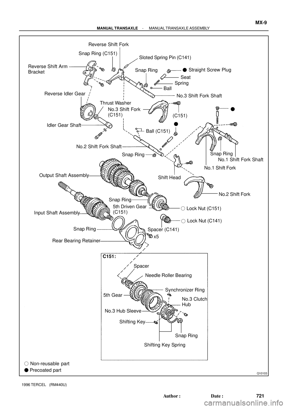
Q10103
Reverse Shift Arm
BracketReverse Shift Fork
Snap RingSnap Ring
Thrust Washer Reverse Idler Gear
Idler Gear Shaft
Ball (C151)Straight Screw Plug
�
BallSpringSeat
�
No.3 Shift Fork
(C151)�
No.2 Shift Fork Shaft
Output Shaft Assembly
Shift HeadNo.1 Shift Fork Shaft
No.1 Shift Fork
No.2 Shift Fork
Lock Nut (C141)
�
5th Driven Gear
(C151)
x5
Spacer Snap Ring
Rear Bearing Retainer
Needle Roller Bearing
5th GearSynchronizer Ring
No.3 Hub Sleeve
Shifting Key
� Non-reusable part
� Precoated partNo.3 Clutch
Hub
Snap Ring
Shifting Key SpringLock Nut (C151) �
Input Shaft AssemblySnap Ring
Spacer (C141)
No.3 Shift Fork Shaft Snap Ring (C151)
Snap RingSloted Spring Pin (C141)
(C151)
C151:
- MANUAL TRANSAXLEMANUAL TRANSAXLE ASSEMBLY
MX-9
721 Author�: Date�:
1996 TERCEL (RM440U)
Page 725 of 1202

HINT:
�Install the No.3 clutch hub and shifting keys t")
Q06532
SST
Engine Side
Q06533
SST
Socket Wrench
N00174
SST
SST
Q06514
x5 MX-12
- MANUAL TRANSAXLEMANUAL TRANSAXLE ASSEMBLY
1996 TERCEL (RM440U)
HINT:
�Install the No.3 clutch hub and shifting keys to the hub
sleeve.
�Install the shifting key springs under the shifting keys.
NOTICE:
At the time of reassembly, position the key springs so that
their end gaps are not in line.
�Support the tip of the input shaft with a spacer or such
to raise the transaxle assembly.
�Using SST and a hammer, drive in the No.3 hub sleeve
assembly with the No.3 shift fork.
SST 09612-2201 1
NOTICE:
At the time of reassembly, align the synchronizer ring slots
with the shifting keys.
13. C151:
REMOVE 5TH DRIVEN GEAR
Using SST and a socket wrench, remove the 5th driven gear.
SST 09950-40010
HINT:
At the time of reassembly, please refer to the following item.
Using SST, install the 5th driven gear.
SST 09309-12020
14. REMOVE REAR BEARING RETAINER
Remove the 5 bolts and retainer.
Torque: 27 N´m (280 kgf´cm, 20 ft´lbf)
15. REMOVE BEARING SNAP RING
Using a snap ring expander, remove the 2 snap rings.
HINT:
If it is difficult to remove and install the snap rings, pull up the
shafts.
Page 728 of 1202
N00047
CM0141
- MANUAL TRANSAXLEMANUAL TRANSAXLE ASSEMBLY
MX-15
1996 TERCEL (RM440U)
(e) C151:
Using a magnetic finger, remove the 2 balls from the re-
verse shift fork.
(f) Remove the No.3 shift fork shaft and reverse shift fork.
(g) Pull out the No.1 shift fork shaft.
(h) Remove the No.1 and No.2 shift forks.
24. REMOVE INPUT AND OUTPUT SHAFTS TOGETHER
FROM TRANSAXLE CASE
25. REMOVE DIFFERENTIAL CASE ASSEMBLY
HINT:
Before reassembly, inspect the differential side bearing pre-
load.
26. REMOVE MAGNET FROM TRANSAXLE CASE
27. REMOVE NO.3 HUB SLEEVE, SHIFTING KEY AND
SPRING FROM NO.3 CLUTCH HUB
Using a screwdriver, remove the 3 shifting keys and 2 springs
from the No.3 clutch hub.

Luggage Compartment")

(b) Slowly turn the crankshaft pulley 2 revolutions from TDC
to TDC.
NOTICE")


(e) C151:
Using a magnetic finger, remove the 2 balls from the re-
verse shift fork.
(f) Remove the No.3 shift fo")