Page 432 of 1202
EM18V-02
EM-10
- ENGINE MECHANICALIDLE SPEED
431 Author�: Date�:
1996 TERCEL (RM440U)
IDLE SPEED
INSPECTION
1. INITIAL CONDITIONS
(a) Engine coolant at normal operating temperature.
(b) Air cleaner installed.
(c) All pipes and hoses of air induction system connected.
(d) All accessories switched OFF.
(e) All vacuum lines properly connected.
HINT:
All vacuum hoses for EGR system, etc. should be properly connected.
(f) SFI system wiring connectors fully plugged.
(g) Ignition timing set correctly.
(h) Transmission in neutral position.
2. CONNECT TOYOTA HAND-HELD TESTER OR OBDII SCAN TOOL (See page EM-9)
3. INSPECT IDLE SPEED
(a) Race the engine speed at 2,500 rpm for approx. 90 seconds.
(b) Check the idle speed.
Idle speed:
750 ± 50 rpm
(w/ Cooling fan OFF and transmission in neutral position)
If the idle speed is not as specified, check the IAC valve and air intake system.
4. DISCONNECT TOYOTA HAND-HELD TESTER OR OBDII SCAN TOOL
Page 541 of 1202
SF0X0-03
MF-16
- MFIINJECTOR
540 Author�: Date�:
1996 TERCEL (RM440U)
INJECTOR
ON-VEHICLE INSPECTION
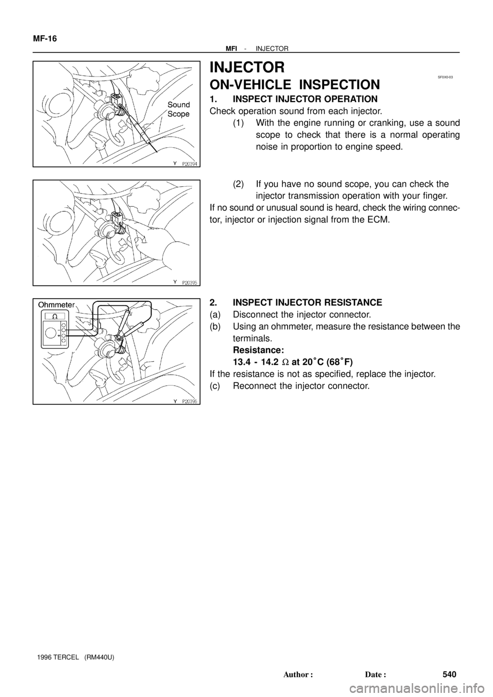
1. INSPECT INJECTOR OPERATION
Check operation sound from each injector.
(1) With the engine running or cranking, use a sound
scope to check that there is a normal operating
noise in proportion to engine speed.
(2) If you have no sound scope, you can check the
injector transmission operation with your finger.
If no sound or unusual sound is heard, check the wiring connec-
tor, injector or injection signal from the ECM.
2. INSPECT INJECTOR RESISTANCE
(a) Disconnect the injector connector.
(b) Using an ohmmeter, measure the resistance between the
terminals.
Resistance:
13.4 - 14.2 W at 20°C (68°F)
If the resistance is not as specified, replace the injector.
(c) Reconnect the injector connector.
Page 558 of 1202
SF199-02
- MFIIDLE AIR CONTROL (IAC) VALVE
MF-33
557 Author�: Date�:
1996 TERCEL (RM440U)
IDLE AIR CONTROL (IAC) VALVE
ON-VEHICLE INSPECTION
1. INSPECT IAC VALVE OPERATION
(a) Initial conditions:
�Engine at normal operating temperature
�Idle speed set correctly
�Transmission in neutral position
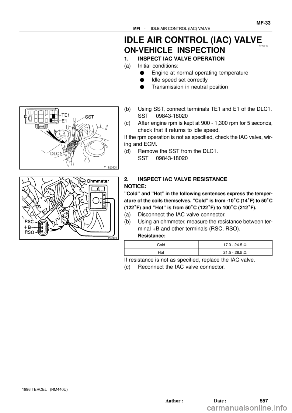
(b) Using SST, connect terminals TE1 and E1 of the DLC1.
SST 09843-18020
(c) After engine rpm is kept at 900 - 1,300 rpm for 5 seconds,
check that it returns to idle speed.
If the rpm operation is not as specified, check the IAC valve, wir-
ing and ECM.
(d) Remove the SST from the DLC1.
SST 09843-18020
2. INSPECT IAC VALVE RESISTANCE
NOTICE:
ºColdº and ºHotº in the following sentences express the temper-
ature of the coils themselves. ºColdº is from -10°C (14°F) to 50°C
(122°F) and ºHotº is from 50°C (122°F) to 100°C (212°F).
(a) Disconnect the IAC valve connector.
(b) Using an ohmmeter, measure the resistance between ter-
minal +B and other terminals (RSC, RSO).
Resistance:
Cold17.0 - 24.5 W
Hot21.5 - 28.5 W
If resistance is not as specified, replace the IAC valve.
(c) Reconnect the IAC valve connector.
Page 718 of 1202
Q06552
Q08461
AB
C
CC
A
Q06446
Q08159
- MANUAL TRANSAXLEMANUAL TRANSAXLE UNIT
MX-5
1996 TERCEL (RM440U)
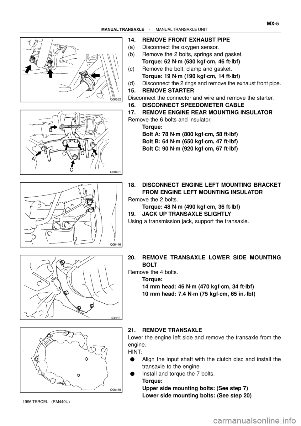
14. REMOVE FRONT EXHAUST PIPE
(a) Disconnect the oxygen sensor.
(b) Remove the 2 bolts, springs and gasket.
Torque: 62 N´m (630 kgf´cm, 46 ft´lbf)
(c) Remove the bolt, clamp and gasket.
Torque: 19 N´m (190 kgf´cm, 14 ft´lbf)
(d) Disconnect the 2 rings and remove the exhaust front pipe.
15. REMOVE STARTER
Disconnect the connector and wire and remove the starter.
16. DISCONNECT SPEEDOMETER CABLE
17. REMOVE ENGINE REAR MOUNTING INSULATOR
Remove the 6 bolts and insulator.
Torque:
Bolt A: 78 N´m (800 kgf´cm, 58 ft´lbf)
Bolt B: 64 N´m (650 kgf´cm, 47 ft´lbf)
Bolt C: 90 N´m (920 kgf´cm, 67 ft´lbf)
18. DISCONNECT ENGINE LEFT MOUNTING BRACKET
FROM ENGINE LEFT MOUNTING INSULATOR
Remove the 2 bolts.
Torque: 48 N´m (490 kgf´cm, 36 ft´lbf)
19. JACK UP TRANSAXLE SLIGHTLY
Using a transmission jack, support the transaxle.
20. REMOVE TRANSAXLE LOWER SIDE MOUNTING
BOLT
Remove the 4 bolts.
Torque:
14 mm head: 46 N´m (470 kgf´cm, 34 ft´lbf)
10 mm head: 7.4 N´m (75 kgf´cm, 65 in.´lbf)
21. REMOVE TRANSAXLE
Lower the engine left side and remove the transaxle from the
engine.
HINT:
�Align the input shaft with the clutch disc and install the
transaxle to the engine.
�Install and torque the 7 bolts.
Torque:
Upper side mounting bolts: (See step 7)
Lower side mounting bolts: (See step 20)
Page 721 of 1202
Z18912
Oil Receiver Pipe
Straight Screw Plug (C141)
�
Slotted Spring Pin (C151)
�Outer Race
Plate Washer Reverse Restrict Pin (C151)
Oil Receiver Pipe
x13 Transmission Case
� Lock Ball Assembly (C151)
�
Back-Up Light Switch
Lock Bolt
Breather Plug
Shift and Select Lever
Shaft Assembly
Selecting Bellcrank Assembly
�Oil Seal
x9
Transmission Case
Cover (C141) Drain Plug
� Non-reusable part
� Precoated partTransmission Case
Cover (C151)
x9
Gasket �Gasket
Filler Plug� �
Straight Screw Plug �Straight Screw Plug (C141)
�Gasket MX-8
- MANUAL TRANSAXLEMANUAL TRANSAXLE ASSEMBLY
720 Author�: Date�:
1996 TERCEL (RM440U)
Page 723 of 1202
MX0B1-02
Q07828
FIPG
N00038
N00039
MX-10
- MANUAL TRANSAXLEMANUAL TRANSAXLE ASSEMBLY
1996 TERCEL (RM440U)
DISASSEMBLY
1. REMOVE RELEASE FORK AND BEARING
HINT:
Apply molybdenum disulphide lithium base grease
(See page CL-17).
2. REMOVE SPEEDOMETER DRIVEN GEAR
Remove the driven gear lock plate set bolt and driven gear.
Torque: 11 N´m (115 kgf´cm, 8 ft´lbf)
3. REMOVE BACK-UP LIGHT SWITCH
Torque: 40 N´m (410 kgf´cm, 30 ft´lbf)
4. REMOVE CONTROL LEVER HOUSING SUPPORT
BRACKET
Remove the 3 bolts and bracket.
Torque: 11 N´m (115 kgf´cm, 8 ft´lbf)
5. REMOVE SELECTING BELLCRANK ASSEMBLY
Remove the 2 bolts and selecting bellcrank assembly.
Torque: 25 N´m (250 kgf´cm, 18 ft´lbf)
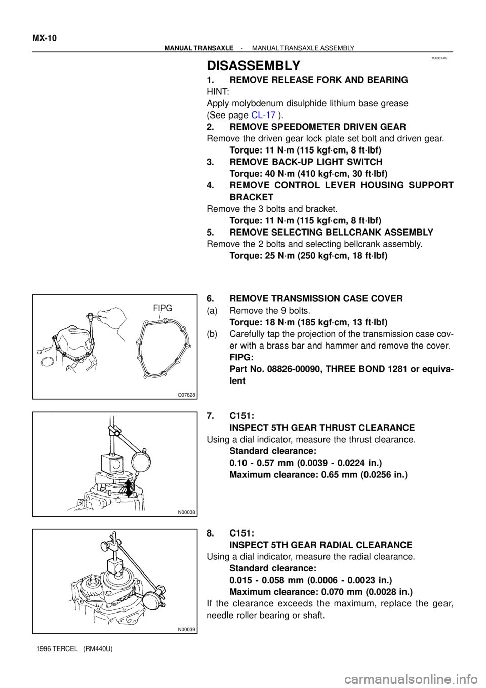
6. REMOVE TRANSMISSION CASE COVER
(a) Remove the 9 bolts.
Torque: 18 N´m (185 kgf´cm, 13 ft´lbf)
(b) Carefully tap the projection of the transmission case cov-
er with a brass bar and hammer and remove the cover.
FIPG:
Part No. 08826-00090, THREE BOND 1281 or equiva-
lent
7. C151:
INSPECT 5TH GEAR THRUST CLEARANCE
Using a dial indicator, measure the thrust clearance.
Standard clearance:
0.10 - 0.57 mm (0.0039 - 0.0224 in.)
Maximum clearance: 0.65 mm (0.0256 in.)
8. C151:
INSPECT 5TH GEAR RADIAL CLEARANCE
Using a dial indicator, measure the radial clearance.
Standard clearance:
0.015 - 0.058 mm (0.0006 - 0.0023 in.)
Maximum clearance: 0.070 mm (0.0028 in.)
If the clearance exceeds the maximum, replace the gear,
needle roller bearing or shaft.
Page 726 of 1202
MT0057
Q06516
C141 Only
Q06524
Z00668
- MANUAL TRANSAXLEMANUAL TRANSAXLE ASSEMBLY
MX-13
1996 TERCEL (RM440U)
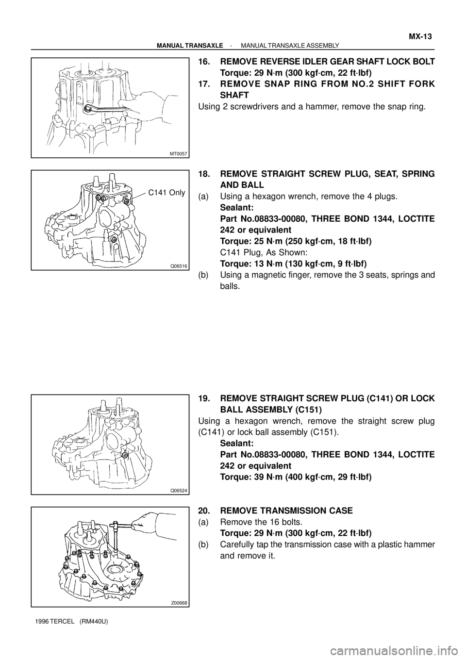
16. REMOVE REVERSE IDLER GEAR SHAFT LOCK BOLT
Torque: 29 N´m (300 kgf´cm, 22 ft´lbf)
17. REMOVE SNAP RING FROM NO.2 SHIFT FORK
SHAFT
Using 2 screwdrivers and a hammer, remove the snap ring.
18. REMOVE STRAIGHT SCREW PLUG, SEAT, SPRING
AND BALL
(a) Using a hexagon wrench, remove the 4 plugs.
Sealant:
Part No.08833-00080, THREE BOND 1344, LOCTITE
242 or equivalent
Torque: 25 N´m (250 kgf´cm, 18 ft´lbf)
C141 Plug, As Shown:
Torque: 13 N´m (130 kgf´cm, 9 ft´lbf)
(b) Using a magnetic finger, remove the 3 seats, springs and
balls.
19. REMOVE STRAIGHT SCREW PLUG (C141) OR LOCK
BALL ASSEMBLY (C151)
Using a hexagon wrench, remove the straight screw plug
(C141) or lock ball assembly (C151).
Sealant:
Part No.08833-00080, THREE BOND 1344, LOCTITE
242 or equivalent
Torque: 39 N´m (400 kgf´cm, 29 ft´lbf)
20. REMOVE TRANSMISSION CASE
(a) Remove the 16 bolts.
Torque: 29 N´m (300 kgf´cm, 22 ft´lbf)
(b) Carefully tap the transmission case with a plastic hammer
and remove it.
Page 749 of 1202
MX07V-03
Z16129
SST
MT0081
Matchmarks
MT0083
MT0084
N00098
SST MX-36
- MANUAL TRANSAXLEDIFFERENTIAL CASE
1996 TERCEL (RM440U)
DISASSEMBLY
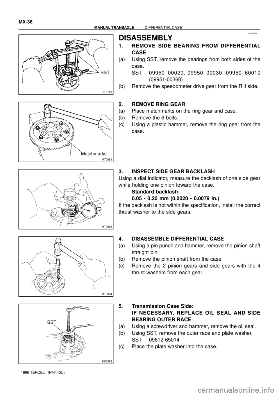
1. REMOVE SIDE BEARING FROM DIFFERENTIAL
CASE
(a) Using SST, remove the bearings from both sides of the
case.
SST 09950- 00020, 09950- 00030, 09950- 60010
(09951-00360)
(b) Remove the speedometer drive gear from the RH side.
2. REMOVE RING GEAR
(a) Place matchmarks on the ring gear and case.
(b) Remove the 6 bolts.
(c) Using a plastic hammer, remove the ring gear from the
case.
3. INSPECT SIDE GEAR BACKLASH
Using a dial indicator, measure the backlash of one side gear
while holding one pinion toward the case.
Standard backlash:
0.05 - 0.20 mm (0.0020 - 0.0079 in.)
If the backlash is not within the specification, install the correct
thrust washer to the side gears.
4. DISASSEMBLE DIFFERENTIAL CASE
(a) Using a pin punch and hammer, remove the pinion shaft
straight pin.
(b) Remove the pinion shaft from the case.
(c) Remove the 2 pinion gears and side gears with the 4
thrust washers from each gear.
5. Transmission Case Side:
IF NECESSARY, REPLACE OIL SEAL AND SIDE
BEARING OUTER RACE
(a) Using a screwdriver and hammer, remove the oil seal.
(b) Using SST, remove the outer race and plate washer.
SST 09612-65014
(c) Place the plate washer into the case.