Page 278 of 1202
A15739
- DIAGNOSTICSENGINE
DI-103
1996 TERCEL (RM440U)
5 Check fuel pump (See page MF-1).
NG Repair or replace fuel pump.
OK
6 Check for open in harness and connector between circuit opening relay and fuel
pump, fuel pump and body ground (See page IN-26).
NG Repair or replace harness or connector.
OK
Check and replace ECM (See page IN-26).
OBD II scan tool (excluding TOYOTA hand-held tester):
1 Check fuel pump operation.
PREPARATION:
(a) Remove the lower finish panel.
(b) Turn the ignition switch ON.
CHECK:
(a) Connect terminal FC of the ECM and the body ground to-
gether.
(b) Check for fuel pressure in the fuel inlet hose when it is
pinched off.
OK:
There is pressure in the inlet hose
HINT:
At this time, you will hear a fuel flowing noise.
OK Check for starter signal circuit.
Page 288 of 1202

R13006
DLC1
E
1
TcTs
BR3904
0.13 sec. 0.13 sec.
ON
OFF
BR3893
Malfunction Code (Example Code 72, 76)
72 67
ON
OFF
0.5 sec. 0.5 sec. 0.5 sec. 0.5 sec.1.5 sec.
2.5 sec.4 sec.
Repeat
- DIAGNOSTICSANTI-LOCK BRAKE SYSTEM
DI-1 13
1996 TERCEL (RM440U)
2. SPEED SENSOR SIGNAL CHECK
(a) Check the speed sensor signal.
(1) Turn the ignition switch OFF.
(2) Using SST, connect terminals Ts and E
1 of the
DLC1.
SST 09843-18020
(3) Start the engine.
(4) Check that the ABS warning light blinks.
HINT:
If the ABS warning light does not blink, inspect the ABS warning
light circuit (See page DI-138).
(5) Drive the vehicle faster than 45 km/h (28 mph) for
several seconds.
(6) Stop the vehicle.
(7) Using SST, connect terminals Tc and E
1 of the
DLC1.
SST 09843-18020
(8) Read the number of blinks of the ABS warning light.
HINT:
See the list of DTCs shown on the next page.
�If every sensor is normal, a normal code is output (A cycle
of 0.25 sec. ON and 0.25 sec. OFF is repeated).
�If 2 or more malfunctions are indicated at the same time,
the lowest numbered code will be displayed 1st.
(9) After doing the check, disconnect terminals Ts and
E
1, and Tc and E1 of the DLC1, and turn ignition
switch OFF.
Page 290 of 1202

DI4LQ-02
- DIAGNOSTICSANTI-LOCK BRAKE SYSTEM
DI-1 15
1996 TERCEL (RM440U)
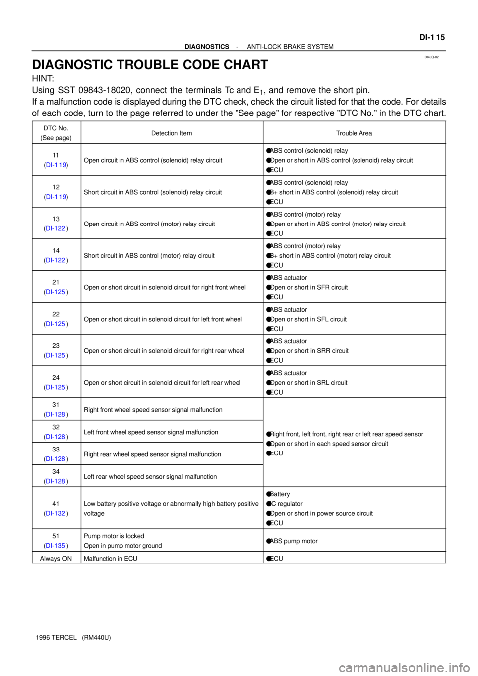
DIAGNOSTIC TROUBLE CODE CHART
HINT:
Using SST 09843-18020, connect the terminals Tc and E
1, and remove the short pin.
If a malfunction code is displayed during the DTC check, check the circuit listed for that the code. For details
of each code, turn to the page referred to under the ºSee pageº for respective ºDTC No.º in the DTC chart.
DTC No.
(See page)Detection ItemTrouble Area
11
(DI-1 19)Open circuit in ABS control (solenoid) relay circuit
�ABS control (solenoid) relay
�Open or short in ABS control (solenoid) relay circuit
�ECU
12
(DI-1 19)Short circuit in ABS control (solenoid) relay circuit
�ABS control (solenoid) relay
�B+ short in ABS control (solenoid) relay circuit
�ECU
13
(DI-122)Open circuit in ABS control (motor) relay circuit
�ABS control (motor) relay
�Open or short in ABS control (motor) relay circuit
�ECU
14
(DI-122)Short circuit in ABS control (motor) relay circuit
�ABS control (motor) relay
�B+ short in ABS control (motor) relay circuit
�ECU
21
(DI-125)Open or short circuit in solenoid circuit for right front wheel
�ABS actuator
�Open or short in SFR circuit
�ECU
22
(DI-125)Open or short circuit in solenoid circuit for left front wheel
�ABS actuator
�Open or short in SFL circuit
�ECU
23
(DI-125)Open or short circuit in solenoid circuit for right rear wheel
�ABS actuator
�Open or short in SRR circuit
�ECU
24
(DI-125)Open or short circuit in solenoid circuit for left rear wheel
�ABS actuator
�Open or short in SRL circuit
�ECU
31
(DI-128)Right front wheel speed sensor signal malfunction
32
(DI-128)Left front wheel speed sensor signal malfunction�Right front, left front, right rear or left rear speed sensor
O htihd iit33
(DI-128)Right rear wheel speed sensor signal malfunction
�Open or short in each speed sensor circuit
�ECU
34
(DI-128)Left rear wheel speed sensor signal malfunction
41
(DI-132)Low battery positive voltage or abnormally high battery positive
voltage
�Battery
�IC regulator
�Open or short in power source circuit
�ECU
51
(DI-135)Pump motor is locked
Open in pump motor ground�ABS pump motor
Always ONMalfunction in ECU�ECU
Page 311 of 1202
W03008
Battery MAIN FL
Fuse BlockALT Driver Side J/B
B 1 1
F6 F7 B-R EA2 2B-R1 1
1J 1CSTOP
G-W
BH
12ABS ECU IF12
G-R
21 Stop Light Switch
R-W
IE11
G-W
1E 1
1
1L
1K 5
G-W G-W
Stop Light
W-BA12STP Driver Side J/B
DI-136
- DIAGNOSTICSANTI-LOCK BRAKE SYSTEM
1996 TERCEL (RM440U)
Stop Light Switch Circuit
CIRCUIT DESCRIPTION
This stop light switch senses whether the brake pedal is depressed or released, and sends the signal to the
ECU.
WIRING DIAGRAM
INSPECTION PROCEDURE
1 Check operation of stop light.
CHECK:
Check that stop light lights up when brake pedal is depressed and turns off when brake pedal is released.
NG Repair stop light circuit (See page BE-28)
OK
DI4LY-02
Page 318 of 1202
F00414
24ABS ECU
AA123DLC1
Ts
16
EC
E1TsL
B-RAEA13
B-RL12 V
J/C
J1
R13006
E1
DLC1
Tc
- DIAGNOSTICSANTI-LOCK BRAKE SYSTEM
DI-143
1996 TERCEL (RM440U)
Ts Terminal Circuit
CIRCUIT DESCRIPTION
The sensor check circuit detects abnormalities in the speed sensor signal which cannot be detected with
the DTC check.
Connecting terminals Ts and E
1 of the DLC1 in the engine compartment starts the check.
WIRING DIAGRAM
INSPECTION PROCEDURE
1 Check voltage between terminals Ts and E1 of DLC1.
CHECK:
(a) Turn the ignition switch ON.
(b) Measure the voltage between terminals Ts and E
1 of the
DLC1.
OK:
Voltage: 10 - 14 V
OK If ABS warning light does not blink even after Ts
and E
1 are connected, ECU may be defective.
NG
DI4M1-02
Page 347 of 1202

R14285 AB0119H00021
Airbag Sensor Assembly ON
IG2 ACC
(+) (-)
DI-172
- DIAGNOSTICSSUPPLEMENTAL RESTRAINT SYSTEM
1996 TERCEL (RM440U)
DTC 31 Airbag Sensor Assembly Malfunction
CIRCUIT DESCRIPTION
The airbag sensor assembly consists of a airbag sensor, safing sensor, drive circuit, diagnosis circuit and
ignition control, etc.
It receives signals from the airbag sensor, judges whether or not the SRS must be activated, and diagnostic
system malfunction.
DTC 31 is recorded when occurrence of a malfunction in the airbag sensor assembly is detected.
DTC No.DTC Detection ConditionTrouble Area
31�Airbag sensor assembly malfunction�Airbag sensor assembly
INSPECTION PROCEDURE
HINT:
When a malfunction code other than code 31 is displayed at the same time, first repair the malfunction indi-
cated by the malfunction code other than code 31.
1 Preparation (See step 1 on page DI-177)
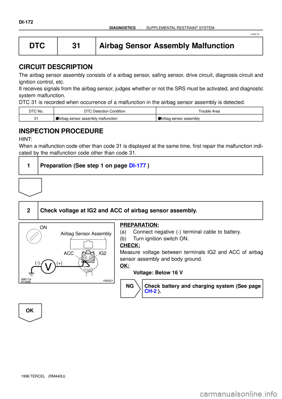
2 Check voltage at IG2 and ACC of airbag sensor assembly.
PREPARATION:
(a) Connect negative (-) terminal cable to battery.
(b) Turn ignition switch ON.
CHECK:
Measure voltage between terminals IG2 and ACC of airbag
sensor assembly and body ground.
OK:
Voltage: Below 16 V
NG Check battery and charging system (See page
CH-2).
OK
DI4MF-02
Page 633 of 1202

IG08E-06
CHECK POWER SUPPLY TO IGNITION COIL
AND IGNITER
SPARK TEST
Replace the camshaft position sensor.
CHECK RESISTANCE OF HIGH-TENSION
CORD (See step 2)
Maximum resistance: 25 kW per cord
CHECK RESISTANCE OF IGNITION COIL
(See step 4) 1. Turn ignition switch to ON.
2. Check that there is battery voltage at
ignition coil positive (+) terminal.
CHECK CONNECTION OF IGNITION COIL IGNITER
Resistance: Cold Hot
Secondary
9.3 - 16.0 kW
11.7 - 18.8 kW
CHECK RESISTANCE OF CAMSHAFT POSITION SENSOR
(See step 5)
Resistance:Cold Hot
985 - 1,600 W1,265 - 1,890 W
CHECK IGT SIGNAL FROM ECM
(See page
DI-84)
CHECK RESISTANCE OF CRANKSHAFT POSITION SENSOR
(See step 6)
Resistance:Cold
Hot
TRY ANOTHER IGNITERReplace the crankshaft position sensor. Replace the ignition coil. Connect securely.
Replace the cord(s).
Check wiring between ignition switch
to ignition coil and igniter.
Check wiring between ECM, distributor
and igniter, and then try another ECM.
NO
OK OK
OK
OK
OK
OKBAD
BAD
BAD
BAD
BAD
BAD
BAD
Primary
0.67 - 1.05 kW0.85 - 1.23 kW
985 - 1,600 W1,265 - 1,890 W
- IGNITIONIGNITION SYSTEM
IG-1
632 Author�: Date�:
1996 TERCEL (RM440U)
IGNITION SYSTEM
ON-VEHICLE INSPECTION
NOTICE:
ºColdº and ºHotº in following sentences express the tem-
perature of the coils themselves. ºColdº is from -10°C
(14°F) to 50°C (122°F) and ºHotº is from 50°C (122°F) to
100°C (212°F).
1. INSPECT SPARK TEST
Check that the spark occurs.
(1) Disconnect the high-tension cord from the spark
plug.
(2) Remove the spark plugs.
(3) Install the spark plugs to the high-tension cord.
(4) Ground the spark plug.
(5) See if spark occurs while engine is being cranked.
NOTICE:
To prevent gasoline from being injected from injectors dur-
ing this test, crank the engine for no more than 5 - 10 se-
conds at time. If the spark done not occur, do the test as fol-
lows:
Page 964 of 1202

RS0Q8-02
N12248
R09725
Spiral Cable
H05490
N12151
RS-2
- SUPPLEMENTAL RESTRAINT SYSTEMSRS AIRBAG
1996 TERCEL (RM440U)
OPERATION
1. STEERING WHEEL PAD (with AIRBAG)
The inflater and bag of the SRS are stored in the steering wheel
pad and cannot be disassembled. The inflater contains a squib,
igniter charge, gas generant, etc., and inflates the bag when
instructed by the airbag sensor assembly.
2. SPIRAL CABLE (in COMBINATION SWITCH)
A spiral cable is used as an electrical joint from the vehicle body
side to the steering wheel.
3. FRONT PASSENGER AIRBAG ASSEMBLY
The inflater and bag of the SRS are stored in the front passen-
ger airbag assembly and cannot be disassembled. The inflater
contains a squib, igniter charge and gas generant, etc., and in-
flates the bag when instructed by the airbag sensor assembly.
4. SRS WARNING LIGHT
The SRS warning light is located on the cluster finish panel. It
goes on to alert the driver of trouble in the system when a mal-
function is detected in the airbag sensor assembly. In normal
operating conditions when the ignition switch is turned to the
ACC or ON position, the light goes on for about 6 seconds and
then goes off.
5. AIRBAG SENSOR ASSEMBLY
The airbag sensor assembly is mounted on the floor inside the
console box. The airbag sensor assembly consists of airbag
sensor, safing sensor, diagnosis circuit, ignition control and
drive circuit, etc. It receives signals from the airbag sensor and
judges whether the SRS must be activated or not.