Page 597 of 1202
CO0Y2-02
(b)
(a)
P20609
(c)(d)
P20754
Plug
(e)
P20755
A/T
(A)
P20610
Radiator Lower Hose
Radiator Lower Support CO-16
- COOLINGRADIATOR
1996 TERCEL (RM440U)
REMOVAL
1. REMOVE ENGINE UNDER COVERS
2. DRAIN ENGINE COOLANT
3. REMOVE RADIATOR RESERVOIR TANK ASSEMBLY
4. REMOVE RADIATOR ASSEMBLY
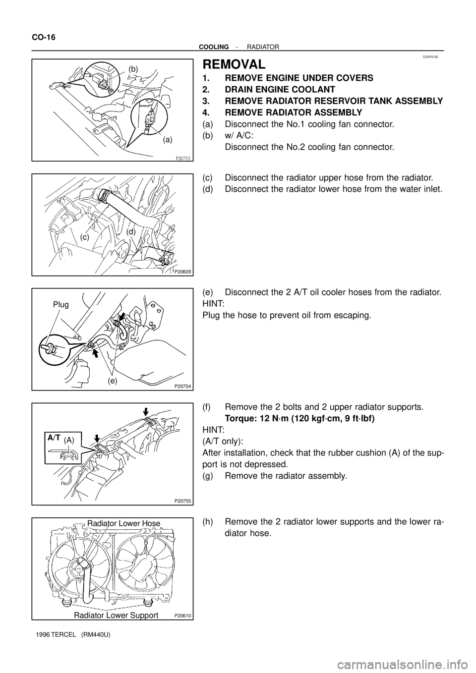
(a) Disconnect the No.1 cooling fan connector.
(b) w/ A/C:
Disconnect the No.2 cooling fan connector.
(c) Disconnect the radiator upper hose from the radiator.
(d) Disconnect the radiator lower hose from the water inlet.
(e) Disconnect the 2 A/T oil cooler hoses from the radiator.
HINT:
Plug the hose to prevent oil from escaping.
(f) Remove the 2 bolts and 2 upper radiator supports.
Torque: 12 N´m (120 kgf´cm, 9 ft´lbf)
HINT:
(A/T only):
After installation, check that the rubber cushion (A) of the sup-
port is not depressed.
(g) Remove the radiator assembly.
(h) Remove the 2 radiator lower supports and the lower ra-
diator hose.
Page 598 of 1202
P20756
w/ A/C
P20757
- COOLINGRADIATOR
CO-17
1996 TERCEL (RM440U)
5. w/ A/C:
REMOVE NO.2 COOLING FAN FROM RADIATOR
Remove the 3 bolts and cooling fan.
6. REMOVE NO.1 COOLING FAN FROM RADIATOR
Remove the 2 bolts and cooling fan.
Page 599 of 1202
CO18B-01
CO1205
Dimension B
Stopper Bolt
Overhaul HandlePart A
ClawSST
P21090
Lock
Plate
Stopper BoltTank
P21091
CO-18
- COOLINGRADIATOR
1996 TERCEL (RM440U)
DISASSEMBLY
1. ASSEMBLE SST
SST 09230-01010
(a) Install the claw to the overhaul handle, inserting it in the
hole in part A as shown in the diagram.
(b) While gripping the handle, adjust the stopper bolt so that
dimension B is as shown in the diagram is 0.2 - 0.5 mm
(0.008 - 0.020 in.).
NOTICE:
If this adjustment is not performed, the claw may be dam-
aged.
2. UNCAULK LOCK PLATES
Using SST to release the caulking, squeeze the handle until
stopped by the stopper bolt.
SST 09230-01010
3. REMOVE TANKS AND O-RINGS
Lightly tap the radiator hose inlet (or outlet) with a soft-faced
hammer, and remove the tank.
Remove the O-ring.
4. A/T:
REMOVE OIL COOLER FROM LOWER TANK
(a) Remove the 2 nuts, spring washers, plate washers and oil
cooler.
(b) Remove the O-ring from the oil cooler.
Page 600 of 1202
CO0Y3-02
P21092
A
B
C
CO1267
Lock PlateLock Plate
Core
N00305
CORRECTWRONG
WRONG
P21093
CORRECT
WRONGTank
Lock
Plate
- COOLINGRADIATOR
CO-19
1996 TERCEL (RM440U)
REASSEMBLY
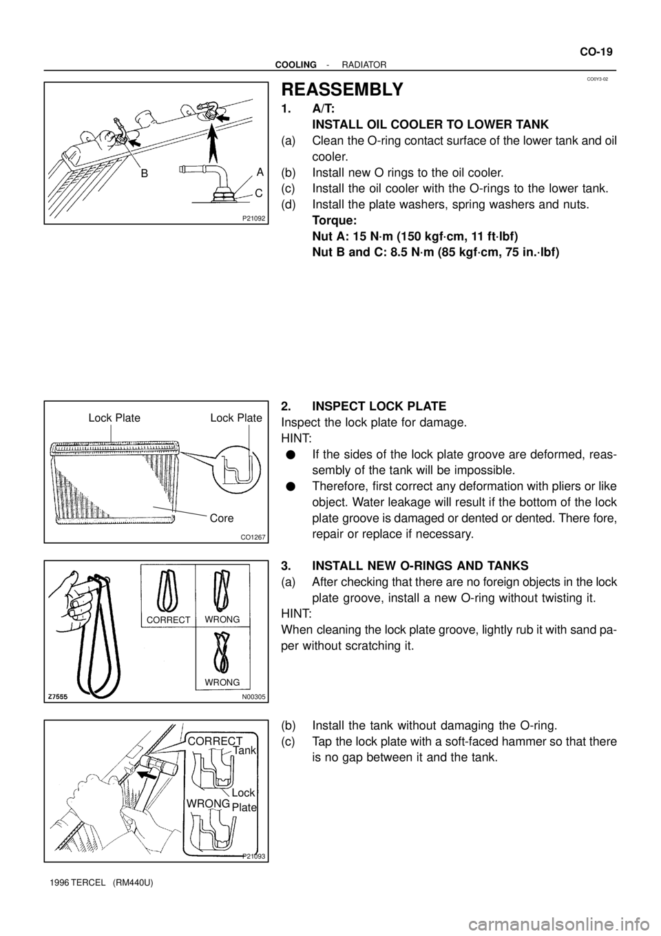
1. A/T:
INSTALL OIL COOLER TO LOWER TANK
(a) Clean the O-ring contact surface of the lower tank and oil
cooler.
(b) Install new O rings to the oil cooler.
(c) Install the oil cooler with the O-rings to the lower tank.
(d) Install the plate washers, spring washers and nuts.
Torque:
Nut A: 15 N´m (150 kgf´cm, 11 ft´lbf)
Nut B and C: 8.5 N´m (85 kgf´cm, 75 in.´lbf)
2. INSPECT LOCK PLATE
Inspect the lock plate for damage.
HINT:
�If the sides of the lock plate groove are deformed, reas-
sembly of the tank will be impossible.
�Therefore, first correct any deformation with pliers or like
object. Water leakage will result if the bottom of the lock
plate groove is damaged or dented or dented. There fore,
repair or replace if necessary.
3. INSTALL NEW O-RINGS AND TANKS
(a) After checking that there are no foreign objects in the lock
plate groove, install a new O-ring without twisting it.
HINT:
When cleaning the lock plate groove, lightly rub it with sand pa-
per without scratching it.
(b) Install the tank without damaging the O-ring.
(c) Tap the lock plate with a soft-faced hammer so that there
is no gap between it and the tank.
Page 601 of 1202
CO1206
Dimension B
Punch Assembly
Overhaul HandleStopper BoltPartSST
P21094
8 7
65
43
2
1
P21095
Stopper
BoltSSTTank
Lock
Plate
P21096
RibBracket
Claw
Z15037
CO-20
- COOLINGRADIATOR
1996 TERCEL (RM440U)
4. ASSEMBLE SST
SST 09230-01010
(a) Install the punch assembly to the overhaul handle, insert-
ing it in the hole in part A as shown in the illustration.
(b) While gripping the handle, adjust the stopper bolt so that
dimension B shown in the diagram is 7.7 mm (0.30 in.)
5. CAULK LOCK PLATE
(a) Lightly press SST against the lock plate in the order
shown in the illustration. After repeating this a few times,
fully caulk the lock plate by squeezing the handle until
stopped by the stopper plate.
SST 09230-01010
HINT:
�Do not stake the areas protruding around the ports,brack-
et or tank ribs.
�The oil cooler (A/T only) and the points attowed in the il-
lustlation cannot be staked with the SST. Use a plier or like
object and be careful not to damage the core plates.
Page 602 of 1202
P21775
H
P21097
SST
CO0766
Clearance
Lock
Plate
O-Ring
- COOLINGRADIATOR
CO-21
1996 TERCEL (RM440U)
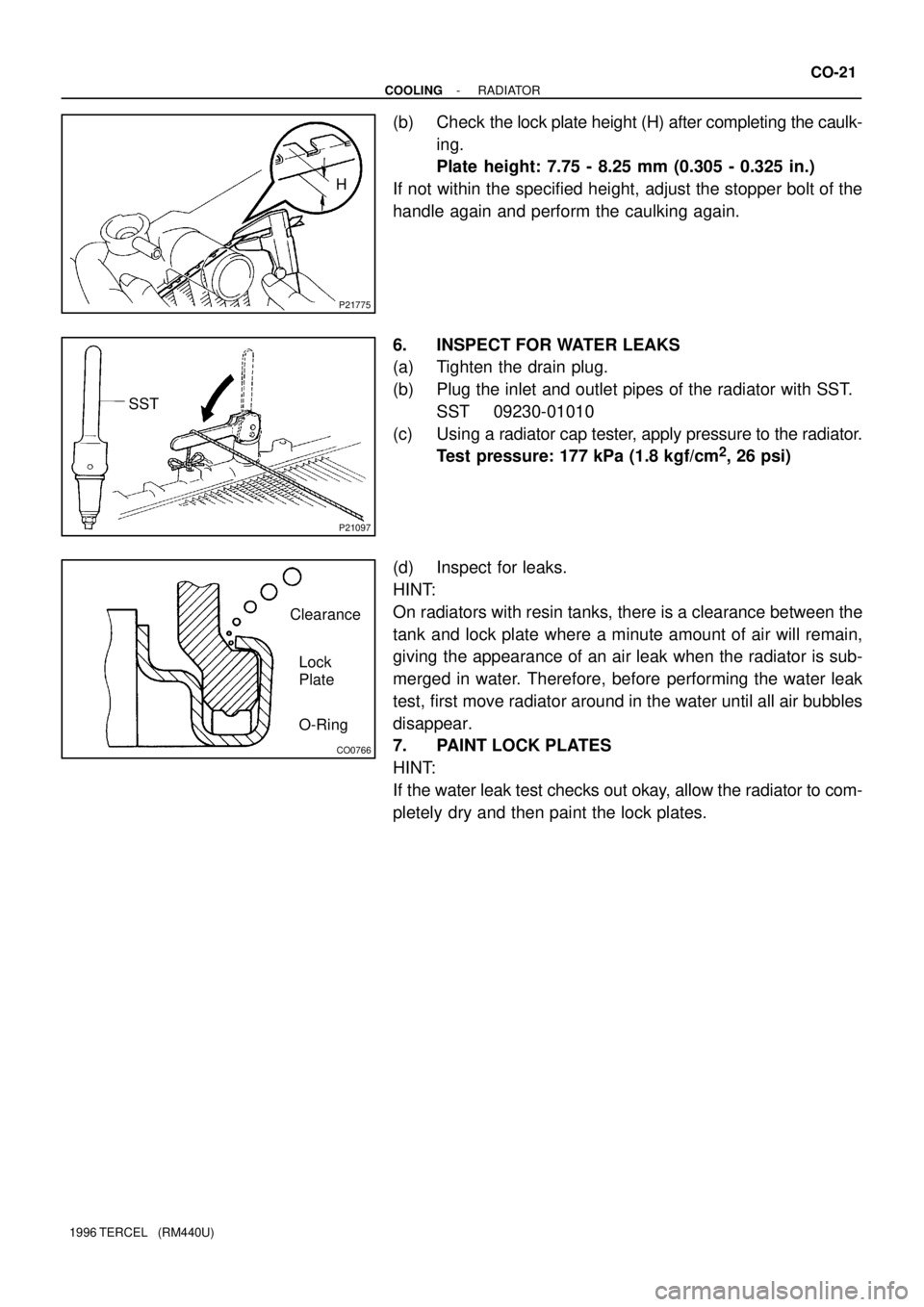
(b) Check the lock plate height (H) after completing the caulk-
ing.
Plate height: 7.75 - 8.25 mm (0.305 - 0.325 in.)
If not within the specified height, adjust the stopper bolt of the
handle again and perform the caulking again.
6. INSPECT FOR WATER LEAKS
(a) Tighten the drain plug.
(b) Plug the inlet and outlet pipes of the radiator with SST.
SST 09230-01010
(c) Using a radiator cap tester, apply pressure to the radiator.
Test pressure: 177 kPa (1.8 kgf/cm
2, 26 psi)
(d) Inspect for leaks.
HINT:
On radiators with resin tanks, there is a clearance between the
tank and lock plate where a minute amount of air will remain,
giving the appearance of an air leak when the radiator is sub-
merged in water. Therefore, before performing the water leak
test, first move radiator around in the water until all air bubbles
disappear.
7. PAINT LOCK PLATES
HINT:
If the water leak test checks out okay, allow the radiator to com-
pletely dry and then paint the lock plates.
Page 603 of 1202
CO0Y4-02
CO-22
- COOLINGRADIATOR
1996 TERCEL (RM440U)
INSTALLATION
Installation is in the reverse order of removal (See page CO-16).
Page 605 of 1202
CO0I8-04
P20876
Air Cleaner Inlet
RH Engine Under
CoverRadiator Tank
Assmbly
No.1 Cooling
Fan Connector
Radiator Upper Hose No.1 Cooling Fan
No.1 Cooling Fan
LH Engine Under Cover CO-24
- COOLINGELECTRIC COOLING FAN
1996 TERCEL (RM440U)
COMPONENTS