Page 318 of 1202
F00414
24ABS ECU
AA123DLC1
Ts
16
EC
E1TsL
B-RAEA13
B-RL12 V
J/C
J1
R13006
E1
DLC1
Tc
- DIAGNOSTICSANTI-LOCK BRAKE SYSTEM
DI-143
1996 TERCEL (RM440U)
Ts Terminal Circuit
CIRCUIT DESCRIPTION
The sensor check circuit detects abnormalities in the speed sensor signal which cannot be detected with
the DTC check.
Connecting terminals Ts and E
1 of the DLC1 in the engine compartment starts the check.
WIRING DIAGRAM
INSPECTION PROCEDURE
1 Check voltage between terminals Ts and E1 of DLC1.
CHECK:
(a) Turn the ignition switch ON.
(b) Measure the voltage between terminals Ts and E
1 of the
DLC1.
OK:
Voltage: 10 - 14 V
OK If ABS warning light does not blink even after Ts
and E
1 are connected, ECU may be defective.
NG
DI4M1-02
Page 447 of 1202

P20496
P20406
- ENGINE MECHANICALCYLINDER HEAD
EM-25
1996 TERCEL (RM440U)
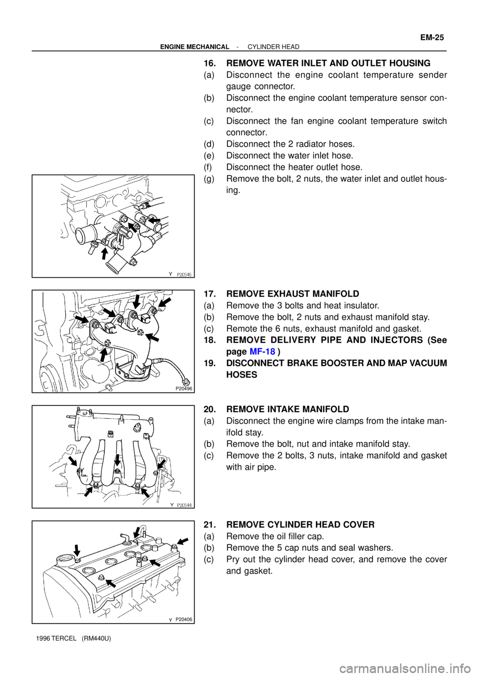
16. REMOVE WATER INLET AND OUTLET HOUSING
(a) Disconnect the engine coolant temperature sender
gauge connector.
(b) Disconnect the engine coolant temperature sensor con-
nector.
(c) Disconnect the fan engine coolant temperature switch
connector.
(d) Disconnect the 2 radiator hoses.
(e) Disconnect the water inlet hose.
(f) Disconnect the heater outlet hose.
(g) Remove the bolt, 2 nuts, the water inlet and outlet hous-
ing.
17. REMOVE EXHAUST MANIFOLD
(a) Remove the 3 bolts and heat insulator.
(b) Remove the bolt, 2 nuts and exhaust manifold stay.
(c) Remote the 6 nuts, exhaust manifold and gasket.
18. REMOVE DELIVERY PIPE AND INJECTORS (See
page MF-18)
19. DISCONNECT BRAKE BOOSTER AND MAP VACUUM
HOSES
20. REMOVE INTAKE MANIFOLD
(a) Disconnect the engine wire clamps from the intake man-
ifold stay.
(b) Remove the bolt, nut and intake manifold stay.
(c) Remove the 2 bolts, 3 nuts, intake manifold and gasket
with air pipe.
21. REMOVE CYLINDER HEAD COVER
(a) Remove the oil filler cap.
(b) Remove the 5 cap nuts and seal washers.
(c) Pry out the cylinder head cover, and remove the cover
and gasket.
Page 479 of 1202
EM1OH-01
- ENGINE MECHANICALENGINE UNIT
EM-57
1996 TERCEL (RM440U)
REMOVAL
1. REMOVE BATTERY
2. REMOVE HOOD
3. REMOVE ENGINE UNDER COVERS
4. DRAIN ENGINE COOLANT
5. DRAIN TRANSAXLE OIL (FLUID)
6. REMOVE AIR CLEANER ASSEMBLY WITH AIR IN-
TAKE CONNECTOR
7. REMOVE RADIATOR (See page CO-16)
8. DISCONNECT ACCELERATOR CABLE
9. DISCONNECT FUEL HOSE
Remove the union bolt and gaskets, and disconnect the fuel in-
let hose.
NOTICE:
Catch leaking fuel in a container.
10. REMOVE CHARCOAL CANISTER
(a) Disconnect the canister hoses.
(b) Remove the charcoal canister.
11. DISCONNECT HOSES
(a) Disconnect the brake booster vacuum hose.
(b) Disconnect the MAP sensor hose.
(c) Disconnect the heater hoses.
12. DISCONNECT SPEEDOMETER CABLE FROM
TRANSAXLE
13. w/ PS:
DISCONNECT IDLE-UP AIR HOSES FROM AIR CON-
TROL VALVE
14. DISCONNECT ENGINE WIRE HARNESS
Disconnect these connectors and wires:
�Main heated oxygen sensor connector
�Oil pressure switch connector
Page 488 of 1202

EM-66
- ENGINE MECHANICALENGINE UNIT
1996 TERCEL (RM440U)
15. CONNECT ENGINE WIRE HARNESS
Connect these connectors and wires:
�Main heated oxygen sensor connector
�Oil pressure switch connector
�Engine coolant temperature sender gauge
connector
�Engine coolant temperature sensor connector
�Camshaft position sensor connector
�EGR VSV
�Fan engine coolant temperature switch connector
�A/T only:
Lock-up solenoid connector
�A/T only:
Park/Neutral position switch connector
�M/T only:
Backup light switch connector
�A/T only:
No.2 vehicle speed sensor connector
�Ground strap
�Throttle position sensor connector
�IAC valve connector
�Injector connectors
�Crankshaft position sensor connector
�Knock sensor connector
�Starter connector and wire
�Generator connector and wire
16. w/ PS:
CONNECT IDLE-UP AIR HOSES TO AIR CONTROL
VA LV E
17. CONNECT SPEEDOMETER CABLE
18. CONNECT HOSES
(a) Connect the brake booster vacuum hose.
(b) Connect the MAP sensor hose.
(c) Connect the heater hoses.
Page 827 of 1202

SA114-03
R11682
F03986
F03987
SA-10
- SUSPENSION AND AXLEFRONT AXLE HUB
1996 TERCEL (RM440U)
REMOVAL
1. REMOVE FRONT WHEEL
Torque: 103 N´m (1,050 kgf´cm, 76 ft´lbf)
2. w/ ABS
REMOVE BOLT AND ABS SPEED SENSOR
Torque: 7.8 N´m (80 kgf´cm, 69 in.´lbf)
3. REMOVE FRONT BRAKE CALIPER AND DISC
(a) Remove the 2 bolts and brake caliper from the steering
knuckle.
Torque: 88 N´m (900 kgf´cm, 65 in.´lbf)
(b) Support the brake caliper securely.
(c) Remove the disc.
4. CHECK BACKLASH IN BEARING SHAFT DIRECTION
Using a dial indicator, check the backlash near the center of the
axle hub, and check the backlash in the bearing shaft direction.
Maximum: 0.05 mm (0.0020 in.)
If the backlash exceeds the maximum, replace the bearing.
5. CHECK AXLE HUB DEVIATION
Using a dial indicator, check the deviation at the surface of the
axle hub outside the hub bolt.
Maximum: 0.05 mm (0.0020 in.)
If the deviation exceeds the maximum, replace the axle hub.
6. REMOVE DRIVE SHAFT LOCK NUT
(a) Install the brake disc and caliper.
(b) Remove the cotter pin and lock cap.
(c) With applying the brakes, remove the nut.
Torque: 216 N´m (2,200 kgf´cm, 159 ft´lbf)
(d) Remove the brake caliper and disc.
7. LOOSEN 2 NUTS ON LOWER SIDE OF SHOCK AB-
SORBER
Torque: 245 N´m (2,500 kgf´cm, 181 ft´lbf)
HINT:
�Do not remove the 2 bolts.
�Coat the nut's thread with engine oil.
Page 835 of 1202

SA128-02
FA1535
SST
F03986
SA-18
- SUSPENSION AND AXLEFRONT DRIVE SHAFT
1996 TERCEL (RM440U)
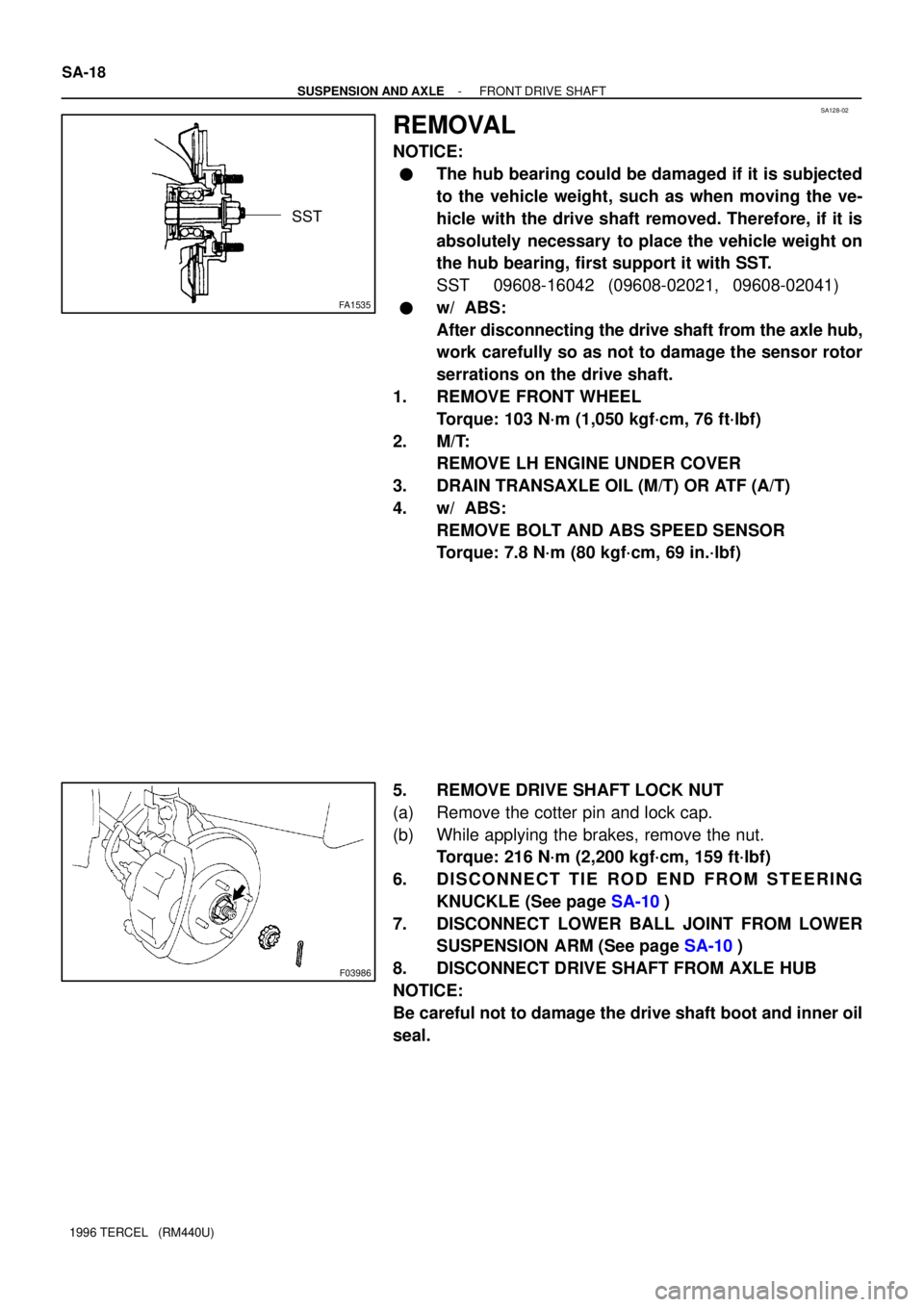
REMOVAL
NOTICE:
�The hub bearing could be damaged if it is subjected
to the vehicle weight, such as when moving the ve-
hicle with the drive shaft removed. Therefore, if it is
absolutely necessary to place the vehicle weight on
the hub bearing, first support it with SST.
SST 09608-16042 (09608-02021, 09608-02041)
�w/ ABS:
After disconnecting the drive shaft from the axle hub,
work carefully so as not to damage the sensor rotor
serrations on the drive shaft.
1. REMOVE FRONT WHEEL
Torque: 103 N´m (1,050 kgf´cm, 76 ft´lbf)
2. M/T:
REMOVE LH ENGINE UNDER COVER
3. DRAIN TRANSAXLE OIL (M/T) OR ATF (A/T)
4. w/ ABS:
REMOVE BOLT AND ABS SPEED SENSOR
Torque: 7.8 N´m (80 kgf´cm, 69 in.´lbf)
5. REMOVE DRIVE SHAFT LOCK NUT
(a) Remove the cotter pin and lock cap.
(b) While applying the brakes, remove the nut.
Torque: 216 N´m (2,200 kgf´cm, 159 ft´lbf)
6. DISCONNECT TIE ROD END FROM STEERING
KNUCKLE (See page SA-10)
7. DISCONNECT LOWER BALL JOINT FROM LOWER
SUSPENSION ARM (See page SA-10)
8. DISCONNECT DRIVE SHAFT FROM AXLE HUB
NOTICE:
Be careful not to damage the drive shaft boot and inner oil
seal.
Page 894 of 1202
BR0S4-05
R15521
Fender Liner
Front Speed
Sensor
Sensor Rotor
- BRAKEFRONT SPEED SENSOR
BR-41
915 Author�: Date�:
1996 TERCEL (RM440U)
FRONT SPEED SENSOR
COMPONENTS
Page 895 of 1202
BR0S5-06
R04569
R04570
BR-42
- BRAKEFRONT SPEED SENSOR
1996 TERCEL (RM440U)
REMOVAL
1. DISCONNECT SPEED SENSOR CONNECTOR
(a) Remove the fender liner.
(b) Disconnect the speed sensor connector.
2. REMOVE SPEED SENSOR
(a) Remove the 2 clamp bolts and a clip holding the sensor
harness to the body and shock absorber.
Torque: 5.0 N´m (51 kgf´cm, 44 in.´lbf)
(b) Remove the bolt and speed sensor from the steering
knuckle.
Torque: 8.0 N´m (82 kgf´cm, 71 in.´lbf)