Page 438 of 1202
P20528
38.4 mm EM-16
- ENGINE MECHANICALTIMING BELT
1996 TERCEL (RM440U)
3. INSPECT TENSION SPRING
(a) Measure the free length of tension spring.
Free length:
38.4 mm (1.512 in.)
If the free length is not as specified, replace the tension spring.
(b) Measure the tension of the tension spring at the specified
installed length.
Installed tension (at 47.4 mm (1.866 in.)):
32 N (3.3 kgf, 7.3 lbf)
If the installed tension is not as specified, replace the tension
spring.
Page 449 of 1202
P20412
Service Bolt Hole
P20409
P20415
Main Gear
Sub-Gear Service
Bolt
- ENGINE MECHANICALCYLINDER HEAD
EM-27
1996 TERCEL (RM440U)
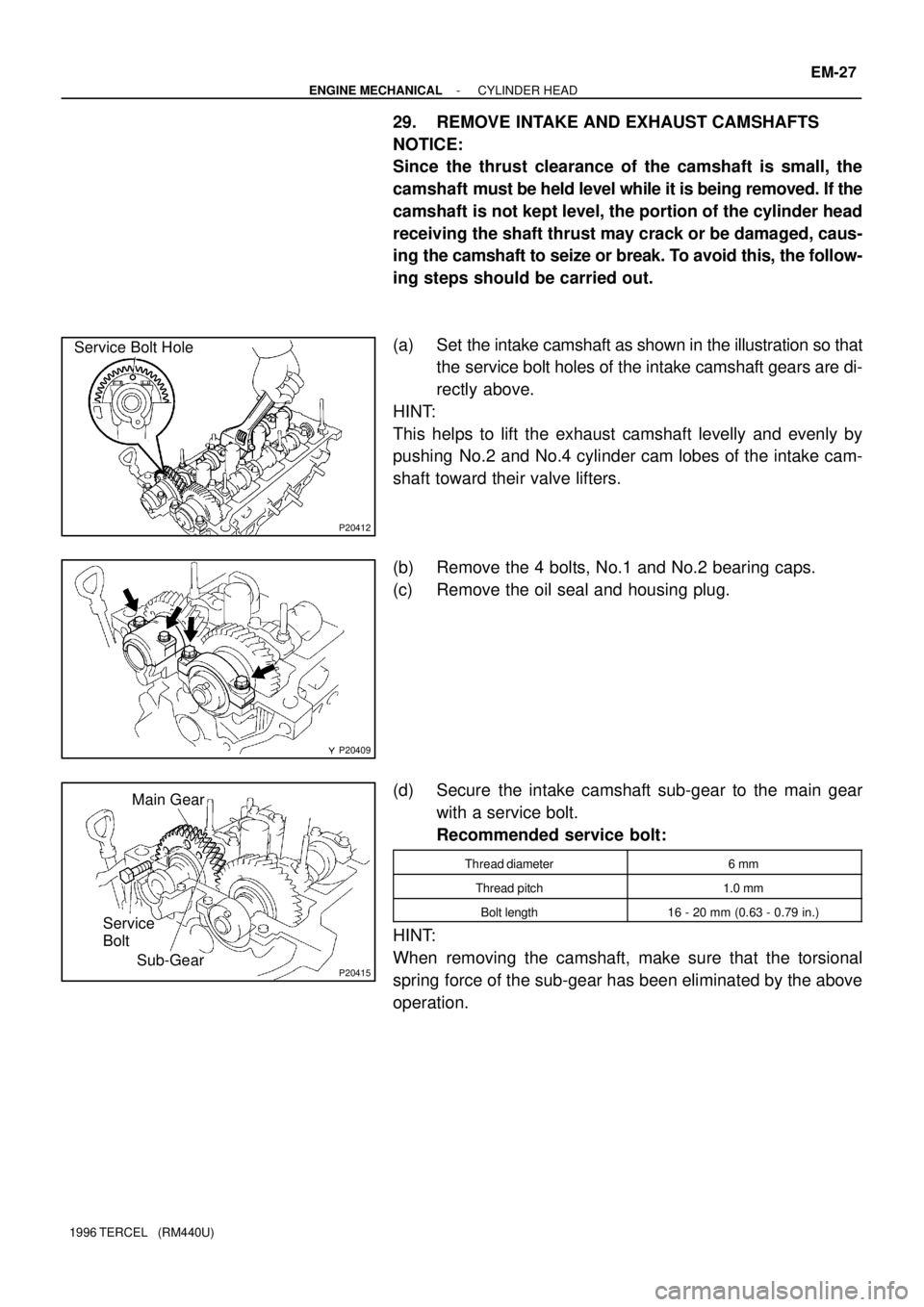
29. REMOVE INTAKE AND EXHAUST CAMSHAFTS
NOTICE:
Since the thrust clearance of the camshaft is small, the
camshaft must be held level while it is being removed. If the
camshaft is not kept level, the portion of the cylinder head
receiving the shaft thrust may crack or be damaged, caus-
ing the camshaft to seize or break. To avoid this, the follow-
ing steps should be carried out.
(a) Set the intake camshaft as shown in the illustration so that
the service bolt holes of the intake camshaft gears are di-
rectly above.
HINT:
This helps to lift the exhaust camshaft levelly and evenly by
pushing No.2 and No.4 cylinder cam lobes of the intake cam-
shaft toward their valve lifters.
(b) Remove the 4 bolts, No.1 and No.2 bearing caps.
(c) Remove the oil seal and housing plug.
(d) Secure the intake camshaft sub-gear to the main gear
with a service bolt.
Recommended service bolt:
Thread diameter6 mm
Thread pitch1.0 mm
Bolt length16 - 20 mm (0.63 - 0.79 in.)
HINT:
When removing the camshaft, make sure that the torsional
spring force of the sub-gear has been eliminated by the above
operation.
Page 456 of 1202
P03849
Overall Length
EM0255
P20367
45° Carbide Cutter
Z07819
Width
Z08336
45°
1.0 - 1.4 mm30° EM-34
- ENGINE MECHANICALCYLINDER HEAD
1996 TERCEL (RM440U)
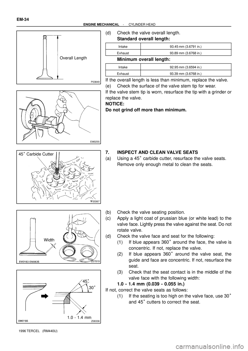
(d) Check the valve overall length.
Standard overall length:
Intake93.45 mm (3.6791 in.)
Exhaust93.89 mm (3.6768 in.)
Minimum overall length:
Intake92.95 mm (3.6594 in.)
Exhaust93.39 mm (3.6768 in.)
If the overall length is less than minimum, replace the valve.
(e) Check the surface of the valve stem tip for wear.
If the valve stem tip is worn, resurface the tip with a grinder or
replace the valve.
NOTICE:
Do not grind off more than minimum.
7. INSPECT AND CLEAN VALVE SEATS
(a) Using a 45° carbide cutter, resurface the valve seats.
Remove only enough metal to clean the seats.
(b) Check the valve seating position.
(c) Apply a light coat of prussian blue (or white lead) to the
valve face. Lightly press the valve against the seat. Do not
rotate valve.
(d) Check the valve face and seat for the following:
(1) If blue appears 360° around the face, the valve is
concentric. If not, replace the valve.
(2) If blue appears 360° around the valve seat, the
guide and face are concentric. If not, resurface the
seat.
(3) Check that the seat contact is in the middle of the
valve face with the following width:
1.0 - 1.4 mm (0.039 - 0.055 in.)
If not, correct the valve seats as follows:
(1) If the seating is too high on the valve face, use 30°
and 45° cutters to correct the seat.
Page 457 of 1202
Z07818
75
60° (IN only)
45°
1.0 - 1.4 mm
P20352
EM0988
Deviation
EM0801
EM0281
- ENGINE MECHANICALCYLINDER HEAD
EM-35
1996 TERCEL (RM440U)
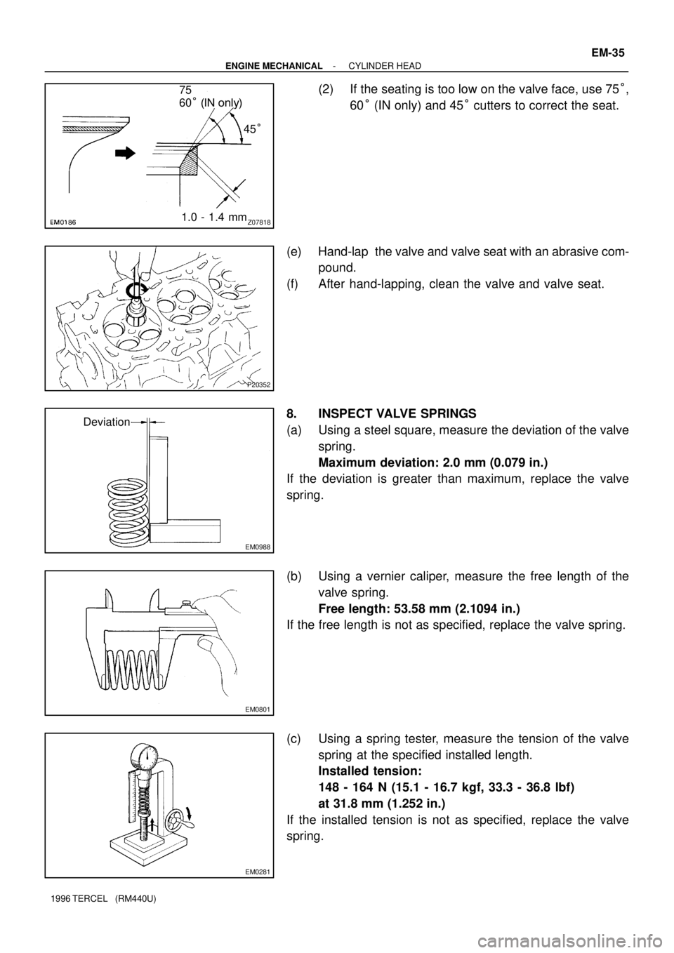
(2) If the seating is too low on the valve face, use 75°,
60° (IN only) and 45° cutters to correct the seat.
(e) Hand-lap the valve and valve seat with an abrasive com-
pound.
(f) After hand-lapping, clean the valve and valve seat.
8. INSPECT VALVE SPRINGS
(a) Using a steel square, measure the deviation of the valve
spring.
Maximum deviation: 2.0 mm (0.079 in.)
If the deviation is greater than maximum, replace the valve
spring.
(b) Using a vernier caliper, measure the free length of the
valve spring.
Free length: 53.58 mm (2.1094 in.)
If the free length is not as specified, replace the valve spring.
(c) Using a spring tester, measure the tension of the valve
spring at the specified installed length.
Installed tension:
148 - 164 N (15.1 - 16.7 kgf, 33.3 - 36.8 lbf)
at 31.8 mm (1.252 in.)
If the installed tension is not as specified, replace the valve
spring.
Page 466 of 1202
P20389
Gasket
EM1OG-01
P20419
EX
(A)
Bi-Hexagon Wrench
(B)IN
(B)
(A)(B)
(B)(B)
(B)
8
61 3
9
10 4 257
(A) (A) (A)(A) IN
EX
P20413
Painted Mark
90°
P20174
(b)(c)
(d)(e)
EM-44
- ENGINE MECHANICALCYLINDER HEAD
1996 TERCEL (RM440U)
INSTALLATION
1. PLACE CYLINDER HEAD ON CYLINDER BLOCK
(a) Place a new cylinder head gasket in position on the cylin-
der block.
NOTICE:
Be careful of the installation direction.
(b) Place the cylinder head in position on the cylinder head
gasket.
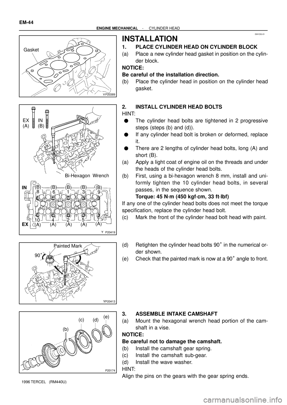
2. INSTALL CYLINDER HEAD BOLTS
HINT:
�The cylinder head bolts are tightened in 2 progressive
steps (steps (b) and (d)).
�If any cylinder head bolt is broken or deformed, replace
it.
�There are 2 lengths of cylinder head bolts, long (A) and
short (B).
(a) Apply a light coat of engine oil on the threads and under
the heads of the cylinder head bolts.
(b) First, using a bi-hexagon wrench 8 mm, install and uni-
formly tighten the 10 cylinder head bolts, in several
passes, in the sequence shown.
Torque: 45 N´m (450 kgf´cm, 33 ft´lbf)
If any one of the cylinder head bolts does not meet the torque
specification, replace the cylinder head bolt.
(c) Mark the front of the cylinder head bolt head with paint.
(d) Retighten the cylinder head bolts 90° in the numerical or-
der shown.
(e) Check that the painted mark is now at a 90° angle to front.
3. ASSEMBLE INTAKE CAMSHAFT
(a) Mount the hexagonal wrench head portion of the cam-
shaft in a vise.
NOTICE:
Be careful not to damage the camshaft.
(b) Install the camshaft gear spring.
(c) Install the camshaft sub-gear.
(d) Install the wave washer.
HINT:
Align the pins on the gears with the gear spring ends.
Page 528 of 1202
P20175
New
Gasket
FI1654
Fulcrum Length
SST
30 cm
FI4295
CORRECT
WRONG
WRONG Delivery Pipe O-Ring
Grommet
Injector
FI4296
Delivery
Pipe
O-Ring
Grommet
InjectorCylinder Head
- MFIMFI SYSTEM
MF-3
527 Author�: Date�:
1996 TERCEL (RM440U)
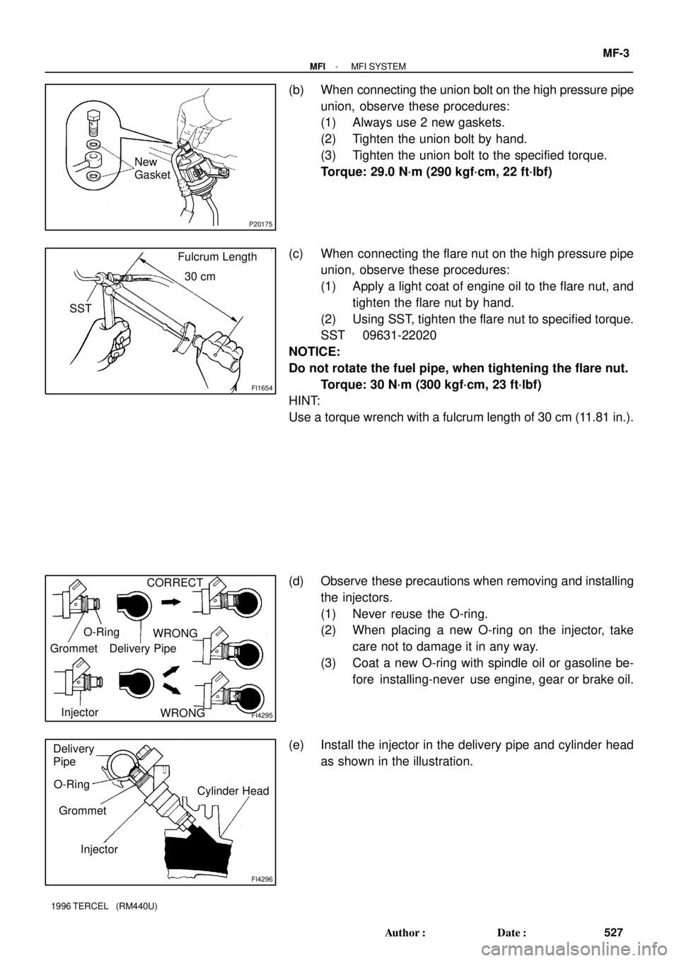
(b) When connecting the union bolt on the high pressure pipe
union, observe these procedures:
(1) Always use 2 new gaskets.
(2) Tighten the union bolt by hand.
(3) Tighten the union bolt to the specified torque.
Torque: 29.0 N´m (290 kgf´cm, 22 ft´lbf)
(c) When connecting the flare nut on the high pressure pipe
union, observe these procedures:
(1) Apply a light coat of engine oil to the flare nut, and
tighten the flare nut by hand.
(2) Using SST, tighten the flare nut to specified torque.
SST 09631-22020
NOTICE:
Do not rotate the fuel pipe, when tightening the flare nut.
Torque: 30 N´m (300 kgf´cm, 23 ft´lbf)
HINT:
Use a torque wrench with a fulcrum length of 30 cm (11.81 in.).
(d) Observe these precautions when removing and installing
the injectors.
(1) Never reuse the O-ring.
(2) When placing a new O-ring on the injector, take
care not to damage it in any way.
(3) Coat a new O-ring with spindle oil or gasoline be-
fore installing-never use engine, gear or brake oil.
(e) Install the injector in the delivery pipe and cylinder head
as shown in the illustration.
Page 550 of 1202
SF0X7-03
BO0919
CrackLeakage
Defomation
Z00085
Fulcrum
Length
30 cm
(11.81 in.) Use SST
30 N´m
(310 kgf´cm, 22 ft´lbf)
SST: 09631-22020SST
FU0041
2 - 7 mm (0.08 - 0.28 in.)
Pipe Hose
0 - 3 mm (0 - 0.12 in.)
FI6138
Fuel Inlet Hose
2.5 mm (0.1 in.) or less
- MFIFUEL TANK AND LINE
MF-25
1996 TERCEL (RM440U)
INSPECTION
INSPECT FUEL TANK AND LINE
(a) Check the fuel lines for cracks or leakage, and all connec-
tions for deformation.
(b) Check the fuel tank vapor vent system hoses and connec-
tions for looseness, sharp bends or damage.
(c) Check the fuel tank for deformation, cracks, fuel leakage
or tank band looseness.
(d) Check the filler neck for damage or fuel leakage.
(e) Hose and the tube connections are as shown in the il-
lustration.
(f) Make sure the hose clamps do not interfere with the tank,
tubes, hoses and other parts.
If a problem is found, repair or replace the parts as necessary.
Page 619 of 1202
LU08B-04
P20919
SST
LU0490
SST
- LUBRICATIONOIL AND FILTER
LU-3
1996 TERCEL (RM440U)
REPLACEMENT
CAUTION:
�Prolonged and repeated contact with mineral oil will
result in the removal of natural fats from the skin,
leading to dryness, irritation and dermatitis. In addi-
tion, used engine oil contains potentially harmful
contaminants which may cause skin cancer. Ade-
quate means of skin protection and washing facilities
should be provided.
�Care should be taken, therefore, when changing en-
gine oil, to minimize the frequency and length of time
your skin is exposed to used engine oil. Protective
clothing and gloves, that cannot be penetrated by oil,
should be worn. Wash your skin throughly with soap
and water, or use waterless hand cleaner, to remove
any used engine oil. Do not use gasoline, thinners, or
solvents.
�In order to preserve the environment, used oil must
be disposed of only at designated disposal sites.
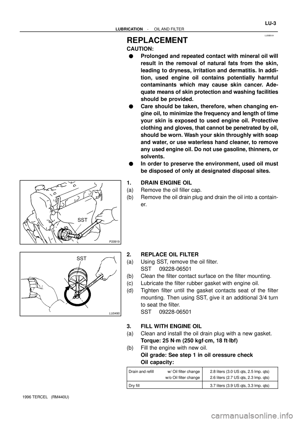
1. DRAIN ENGINE OIL
(a) Remove the oil filler cap.
(b) Remove the oil drain plug and drain the oil into a contain-
er.
2. REPLACE OIL FILTER
(a) Using SST, remove the oil filter.
SST 09228-06501
(b) Clean the filter contact surface on the filter mounting.
(c) Lubricate the filter rubber gasket with engine oil.
(d) Tighten filter until the gasket contacts seat of the filter
mounting. Then using SST, give it an additional 3/4 turn
to seat the filter.
SST 09228-06501
3. FILL WITH ENGINE OIL
(a) Clean and install the oil drain plug with a new gasket.
Torque: 25 N´m (250 kgf´cm, 18 ft´lbf)
(b) Fill the engine with new oil.
Oil grade: See step 1 in oil oressure check
Oil capacity:
Drain and refill w/ Oil filter change
w/o Oil filter change2.8 liters (3.0 US qts, 2.5 lmp. qts)
2.6 liters (2.7 US qts, 2.3 lmp. qts)
Dry fill3.7 liters (3.9 US qts, 3.3 lmp. qts)