Page 187 of 1202

DI4LF-02
- DIAGNOSTICSENGINE
DI-13
1996 TERCEL (RM440U)
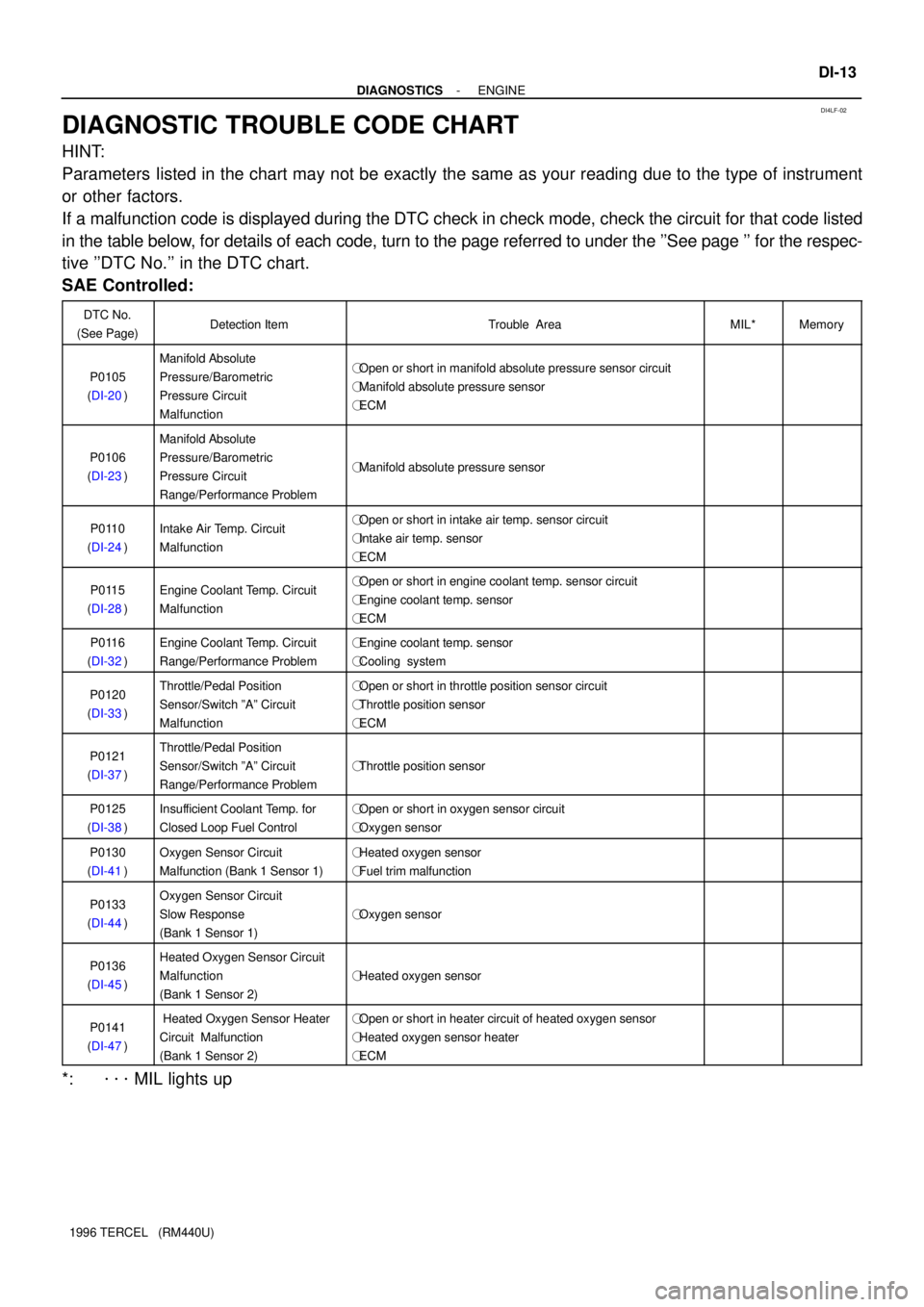
DIAGNOSTIC TROUBLE CODE CHART
HINT:
Parameters listed in the chart may not be exactly the same as your reading due to the type of instrument
or other factors.
If a malfunction code is displayed during the DTC check in check mode, check the circuit for that code listed
in the table below, for details of each code, turn to the page referred to under the ''See page '' for the respec-
tive ''DTC No.'' in the DTC chart.
SAE Controlled:
DTC No.
(See Page)Detection ItemTrouble AreaMIL*Memory
P0105
(DI-20)
Manifold Absolute
Pressure/Barometric
Pressure Circuit
Malfunction�Open or short in manifold absolute pressure sensor circuit
�Manifold absolute pressure sensor
�ECM
��
P0106
(DI-23)
Manifold Absolute
Pressure/Barometric
Pressure Circuit
Range/Performance Problem
�Manifold absolute pressure sensor��
P0110
(DI-24)Intake Air Temp. Circuit
Malfunction�Open or short in intake air temp. sensor circuit
�Intake air temp. sensor
�ECM
��
P0115
(DI-28)Engine Coolant Temp. Circuit
Malfunction�Open or short in engine coolant temp. sensor circuit
�Engine coolant temp. sensor
�ECM
��
P0116
(DI-32)Engine Coolant Temp. Circuit
Range/Performance Problem�Engine coolant temp. sensor
�Cooling system��
P0120
(DI-33)Throttle/Pedal Position
Sensor/Switch ºAº Circuit
Malfunction�Open or short in throttle position sensor circuit
�Throttle position sensor
�ECM
��
P0121
(DI-37)Throttle/Pedal Position
Sensor/Switch ºAº Circuit
Range/Performance Problem
�Throttle position sensor��
P0125
(DI-38)Insufficient Coolant Temp. for
Closed Loop Fuel Control�Open or short in oxygen sensor circuit
�Oxygen sensor��
P0130
(DI-41)Oxygen Sensor Circuit
Malfunction (Bank 1 Sensor 1)�Heated oxygen sensor
�Fuel trim malfunction��
P0133
(DI-44)Oxygen Sensor Circuit
Slow Response
(Bank 1 Sensor 1)
�Oxygen sensor��
P0136
(DI-45)Heated Oxygen Sensor Circuit
Malfunction
(Bank 1 Sensor 2)
�Heated oxygen sensor��
P0141
(DI-47) Heated Oxygen Sensor Heater
Circuit Malfunction
(Bank 1 Sensor 2)�Open or short in heater circuit of heated oxygen sensor
�Heated oxygen sensor heater
�ECM
��
*: ����� MIL lights up
Page 221 of 1202

A15695
- DIAGNOSTICSENGINE
DI-47
1996 TERCEL (RM440U)
DTC P0135 Heated Oxygen Sensor Heated Circuit
Malfunction (Bank 1 Sensor 1)
DTC P0141 Heated Oxygen Sensor Heated Circuit
Malfunction (Bank 1 Sensor 2)
CIRCUIT DESCRIPTION
Refer to DTC P0125 on page DI-38.
DTC No.DTC Detection ConditionTrouble Area
P0135
When the heater operates, heater current exceeds 2 A
(2 trip detection logic)�Open or short in heater circuit of heated oxygen sensor
Htd htP0135
P0141Heater current of 0.25 A or less when the heater
operates (2 trip detection logic)�Heated oxygen sensor heater
�ECM
WIRING DIAGRAM
Refer to page DI-38.
INSPECTION PROCEDURE
1 Check voltage between terminal HT1, HT2 of ECM connector and body ground.
PREPARATION:
(a) Remove the lower finish panel.
(b) Turn the ignition switch ON.
CHECK:
Measure the voltage between terminal HT1, HT2 of the ECM
connector and the body ground.
OK:
Voltage: 9 - 14 V
OK Check and replace ECM (See page IN-26).
NG
2 Check resistance of heated oxygen sensor heater (See page MF-53).
NG Replace heated oxygen sensor.
OK
DI1ED-1 1
Page 353 of 1202

R05894 AB0117
H00001
Airbag Sensor
Assembly LOCK
Spiral
Cable D SquibP Squib
R14285 AB0119H00021
ON
Airbag Sensor Assembly
ACC
IG2
(+) (-)
DI-178
- DIAGNOSTICSSUPPLEMENTAL RESTRAINT SYSTEM
1996 TERCEL (RM440U)
INSPECTION PROCEDURE
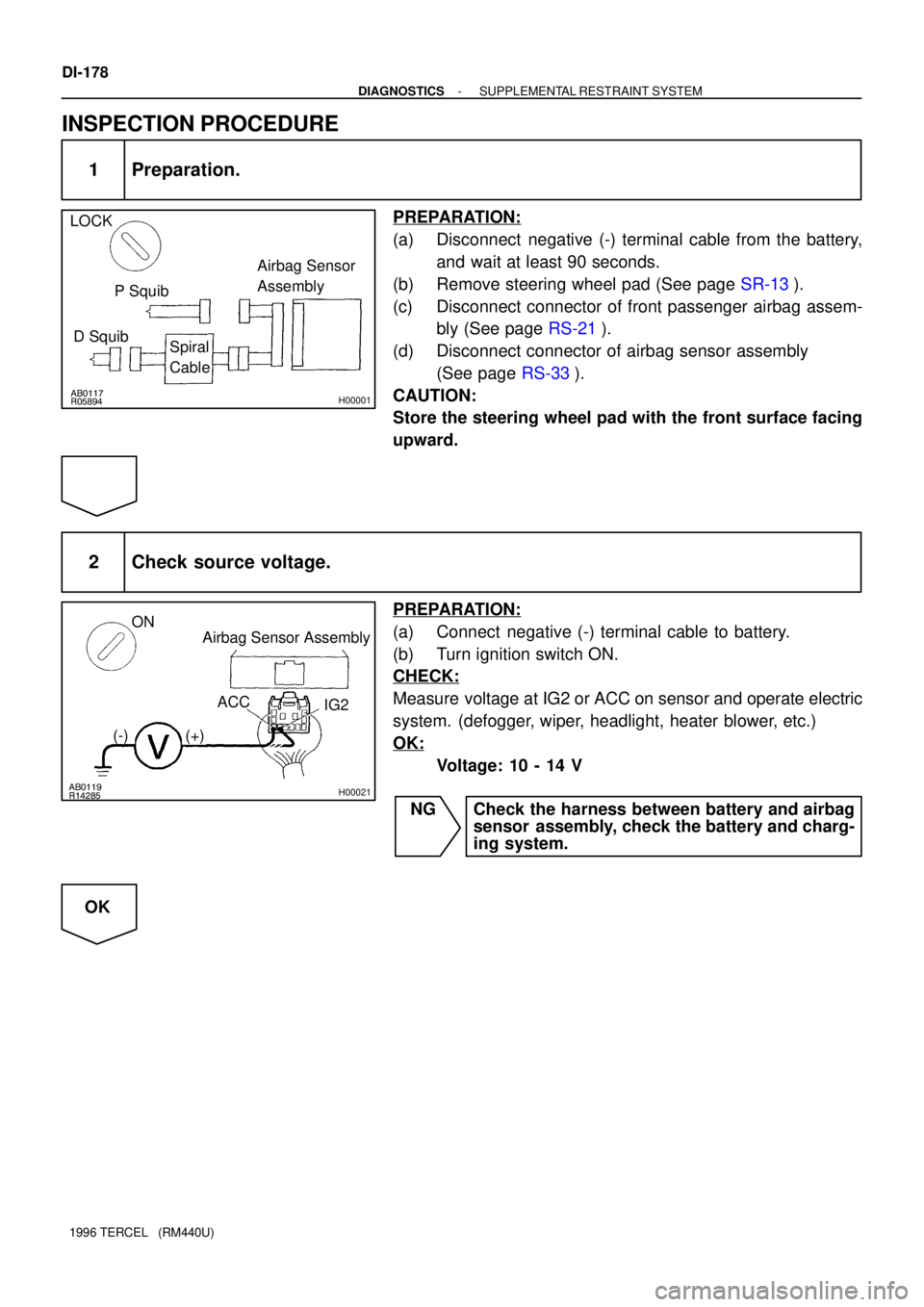
1 Preparation.
PREPARATION:
(a) Disconnect negative (-) terminal cable from the battery,
and wait at least 90 seconds.
(b) Remove steering wheel pad (See page SR-13).
(c) Disconnect connector of front passenger airbag assem-
bly (See page RS-21).
(d) Disconnect connector of airbag sensor assembly
(See page RS-33).
CAUTION:
Store the steering wheel pad with the front surface facing
upward.
2 Check source voltage.
PREPARATION:
(a) Connect negative (-) terminal cable to battery.
(b) Turn ignition switch ON.
CHECK:
Measure voltage at IG2 or ACC on sensor and operate electric
system. (defogger, wiper, headlight, heater blower, etc.)
OK:
Voltage: 10 - 14 V
NG Check the harness between battery and airbag
sensor assembly, check the battery and charg-
ing system.
OK
Page 354 of 1202
H00003
ON
- DIAGNOSTICSSUPPLEMENTAL RESTRAINT SYSTEM
DI-179
1996 TERCEL (RM440U)
3 Does SRS warning light turn off?
PREPARATION:
(a) Turn ignition switch to LOCK.
(b) Connect steering wheel pad connector.
(c) Connect front passenger airbag assembly connector.
(d) Connect airbag sensor assembly connector.
(e) Turn ignition switch ON.
CHECK:
Operate electric system checked in defogger, wiper, headlight,
heater blower, etc. and check that SRS warning light goes off.
NO Check for DTCs. If a DTC is output, perform trou-
bleshooting for the DTC. If a normal code is out-
put, replace airbag sensor assembly.
YES
From the results of the above inspection, the malfunctioning part can now be considered normal.
To make sure of this, use the simulation method to check.
Page 447 of 1202

P20496
P20406
- ENGINE MECHANICALCYLINDER HEAD
EM-25
1996 TERCEL (RM440U)
16. REMOVE WATER INLET AND OUTLET HOUSING
(a) Disconnect the engine coolant temperature sender
gauge connector.
(b) Disconnect the engine coolant temperature sensor con-
nector.
(c) Disconnect the fan engine coolant temperature switch
connector.
(d) Disconnect the 2 radiator hoses.
(e) Disconnect the water inlet hose.
(f) Disconnect the heater outlet hose.
(g) Remove the bolt, 2 nuts, the water inlet and outlet hous-
ing.
17. REMOVE EXHAUST MANIFOLD
(a) Remove the 3 bolts and heat insulator.
(b) Remove the bolt, 2 nuts and exhaust manifold stay.
(c) Remote the 6 nuts, exhaust manifold and gasket.
18. REMOVE DELIVERY PIPE AND INJECTORS (See
page MF-18)
19. DISCONNECT BRAKE BOOSTER AND MAP VACUUM
HOSES
20. REMOVE INTAKE MANIFOLD
(a) Disconnect the engine wire clamps from the intake man-
ifold stay.
(b) Remove the bolt, nut and intake manifold stay.
(c) Remove the 2 bolts, 3 nuts, intake manifold and gasket
with air pipe.
21. REMOVE CYLINDER HEAD COVER
(a) Remove the oil filler cap.
(b) Remove the 5 cap nuts and seal washers.
(c) Pry out the cylinder head cover, and remove the cover
and gasket.
Page 474 of 1202

EM-52
- ENGINE MECHANICALCYLINDER HEAD
1996 TERCEL (RM440U)
HINT:
Avoid applying an excess amount to the surface. Be especially
careful near oil passages.
�Parts must be assembled within 15 minutes of ap-
plication. Otherwise, the material must be removed
and reapplied.
�Immediately remove nozzle from tube and reinstall
cap.
�Do not pour in any coolant until at least 2 hours after
installation is completed.
(c) Install the water outlet housing with the bolt and 2 nuts.
Torque: 17.5 N´m (175 kgf´cm, 13 ft´lbf)
(d) Connect the 2 radiator hoses.
(e) Connect the water inlet hose.
(f) Connect the heater outlet hose.
(g) Connect the engine coolant temperature sensor connec-
tor.
(h) Connect the engine coolant temperature sender gauge
connector.
(i) Connect the fan engine coolant temperature switch con-
nector.
20. INSTALL CAMSHAFT POSITION SENSOR AND EGR
VSV
(a) Install a new O-ring to the position sensor.
(b) Install the position sensor with the bolt.
Torque: 8.0 N´m (80 kgf´cm, 69 in.´lbf)
(c) Install the EGR VSV with the bolt.
Torque: 17.5 N´m (175 kgf´cm, 13 in.´lbf)
(d) Connect the position sensor and EGR VSV connectors.
21. INSTALL EGR VALVE AND VACUUM MODULATOR
(a) Install a new gasket and the EGR valve with the 2 nuts.
Torque: 30 N´m (300 kgf´cm, 22 in.´lbf)
(b) Install the EGR vacuum modulator and bracket with the
bolt.
Page 479 of 1202
EM1OH-01
- ENGINE MECHANICALENGINE UNIT
EM-57
1996 TERCEL (RM440U)
REMOVAL
1. REMOVE BATTERY
2. REMOVE HOOD
3. REMOVE ENGINE UNDER COVERS
4. DRAIN ENGINE COOLANT
5. DRAIN TRANSAXLE OIL (FLUID)
6. REMOVE AIR CLEANER ASSEMBLY WITH AIR IN-
TAKE CONNECTOR
7. REMOVE RADIATOR (See page CO-16)
8. DISCONNECT ACCELERATOR CABLE
9. DISCONNECT FUEL HOSE
Remove the union bolt and gaskets, and disconnect the fuel in-
let hose.
NOTICE:
Catch leaking fuel in a container.
10. REMOVE CHARCOAL CANISTER
(a) Disconnect the canister hoses.
(b) Remove the charcoal canister.
11. DISCONNECT HOSES
(a) Disconnect the brake booster vacuum hose.
(b) Disconnect the MAP sensor hose.
(c) Disconnect the heater hoses.
12. DISCONNECT SPEEDOMETER CABLE FROM
TRANSAXLE
13. w/ PS:
DISCONNECT IDLE-UP AIR HOSES FROM AIR CON-
TROL VALVE
14. DISCONNECT ENGINE WIRE HARNESS
Disconnect these connectors and wires:
�Main heated oxygen sensor connector
�Oil pressure switch connector
Page 488 of 1202

EM-66
- ENGINE MECHANICALENGINE UNIT
1996 TERCEL (RM440U)
15. CONNECT ENGINE WIRE HARNESS
Connect these connectors and wires:
�Main heated oxygen sensor connector
�Oil pressure switch connector
�Engine coolant temperature sender gauge
connector
�Engine coolant temperature sensor connector
�Camshaft position sensor connector
�EGR VSV
�Fan engine coolant temperature switch connector
�A/T only:
Lock-up solenoid connector
�A/T only:
Park/Neutral position switch connector
�M/T only:
Backup light switch connector
�A/T only:
No.2 vehicle speed sensor connector
�Ground strap
�Throttle position sensor connector
�IAC valve connector
�Injector connectors
�Crankshaft position sensor connector
�Knock sensor connector
�Starter connector and wire
�Generator connector and wire
16. w/ PS:
CONNECT IDLE-UP AIR HOSES TO AIR CONTROL
VA LV E
17. CONNECT SPEEDOMETER CABLE
18. CONNECT HOSES
(a) Connect the brake booster vacuum hose.
(b) Connect the MAP sensor hose.
(c) Connect the heater hoses.