Page 667 of 1202

ST0661
Free
Lock
ST0667
P25604
Terminal C
Continuity Terminal 50
P25605
Continuity Terminal 50 Switch
Body
- STARTINGSTARTER (Planetary Type)
ST-21
1996 TERCEL (RM440U)
6. INSPECT CLUTCH AND GEAR
(a) Check the gear teeth on the planetary gear, internal gear
and starter clutch for wear or damage.
If the gear is damaged, replace it.
If the starter clutch teeth are damaged, replace the starter
clutch and also inspect the flywheel ring gear for wear or dam-
age.
(b) Check the starter clutch.
Rotate the clutch pinion gear clockwise and check that it
turns freely. Try to rotate the clutch pinion gear counter-
clockwise and check that it locks.
If necessary, replace the starter clutch.
7. INSPECT MAGNETIC SWITCH
(a) Check the plunger.
Push in the plunger and replace it. Check that it returns
quickly to its original position.
If necessary, replace the magnetic switch.
(b) Check the pull-in coil for open circuit.
Using an ohmmeter, check that there is continuity be-
tween terminals 50 and C.
If there is no continuity, replace the magnetic switch.
(c) Check the hold-in coil for open circuit.
Using an ohmmeter, check that there is continuity be-
tween terminal 50 and the switch body.
If there is no continuity, replace the magnetic switch.
Page 697 of 1202

CL05O-03
- CLUTCHTROUBLESHOOTING
CL-1
696 Author�: Date�:
1996 TERCEL (RM440U)
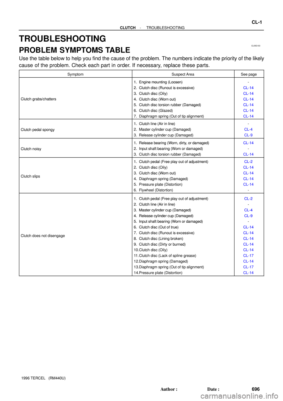
TROUBLESHOOTING
PROBLEM SYMPTOMS TABLE
Use the table below to help you find the cause of the problem. The numbers indicate the priority of the likely
cause of the problem. Check each part in order. If necessary, replace these parts.
SymptomSuspect AreaSee page
1. Engine mounting (Loosen)-1.Engine mounting (Loosen)
2. Clutch disc (Runout is excessive)
-
CL-14
2.Clutch disc (Runout is excessive)
3. Clutch disc (Oily)
CL-14
CL-14
Clutch grabs/chatters
3.Clutch disc (Oily)
4. Clutch disc (Worn out)
CL-14
CL-14Clutch grabs/chatters4.Clutch disc (Worn out)
5. Clutch disc torsion rubber (Damaged)
CL-14
CL-145.Clutch disc torsion rubber (Damaged)
6. Clutch disc (Glazed)
CL 14
CL-146.Clutch disc (Glazed)
7. Diaphragm spring (Out of tip alignment)
CL 14
CL-14
1. Clutch line (Air in line)-
Clutch pedal spongy
1.Clutch line (Air in line)
2. Master cylinder cup (Damaged)
-
CL-4
Clutch edal s ongy2.Master cylinder cu (Damaged)
3. Release cylinder cup (Damaged)
CL 4
CL-9
1. Release bearing (Worn, dirty, or damaged)CL-14
Clutch noisy
1.Release bearing (Worn, dirty, or damaged)
2. Input shaft bearing (Worn or damaged)
CL-14
-Clutch noisy2.In ut shaft bearing (Worn or damaged)
3. Clutch disc torsion rubber (Damaged)CL-14
1. Clutch pedal (Free play out of adjustment)CL-21.Clutch edal (Free lay out of adjustment)
2. Clutch disc (Oily)
CL-2
CL-14
Cl t h li
2.Clutch disc (Oily)
3. Clutch disc (Worn out)
CL-14
CL-14Clutch slips3.Clutch disc (Worn out)
4. Diaphragm spring (Damaged)
CL 14
CL-144.Dia hragm s ring (Damaged)
5. Pressure plate (Distortion)
CL 14
CL-145. Pressure late (Distortion)
6. Flywheel (Distortion)
CL 14
-
1 Clutchpedal (Freeplay out of adjustment)CL-21.Clutch pedal (Free play out of adjustment)
2 Clutch line (Air in line)CL-2
-2.Clutch line (Air in line)
3 Master cylinder cu
p(Damaged)
-
CL-43.Master cylinder cup (Damaged)
4. Release cylinder cu
p(Damaged)
CL-4
CL
-94.Release cylinder cup (Damaged)
5
. Input shaft bearing (Worn or damaged)
CL-9
-5.In ut shaft bearing (Worn or damaged)
6. Clutch disc (Out of true)
-
CL-14
Cl t h d t di
6.Clutch disc (Out of true)
7. Clutch disc (Runout is excessive)
CL-14
CL-14Clutch does not disengage7.Clutch disc (Runout is excessive)
8. Clutch disc (Lining broken)
CL-14
CL-148.Clutch disc (Lining broken)
9. Clutch disc (Dirty or burned)
CL-14
CL-149.Clutch disc (Dirty or burned)
10.Clutch disc (Oily)
CL 14
CL-1410.Clutch disc (Oily)
11. Clutch disc (Lack of spline grease)
CL 14
CL-1711. Clutch disc (Lack of s line grease)
12.Diaphragm spring (Damaged)
CL 17
CL-14gg(g)
13.Diaphragm spring (Out of tip alignment)CL-17gg( g)
14.Pressure plate (Distortion)CL-14
Page 710 of 1202
CL060-03
Z14164
Flywheel
Clutch Disc
Clutch Cover
Boot Release Fork Release Bearing with Hub X6 CL-14
- CLUTCHCLUTCH UNIT
709 Author�: Date�:
1996 TERCEL (RM440U)
CLUTCH UNIT
COMPONENTS
Page 711 of 1202
CL061-01
CL0288Matchmarks
N00413
- CLUTCHCLUTCH UNIT
CL-15
1996 TERCEL (RM440U)
REMOVAL
1. REMOVE TRANSAXLE FROM ENGINE
(See page MX-4)
2. REMOVE CLUTCH COVER AND DISC
(a) Place matchmarks on the flywheel and clutch cover.
(b) Loosen each set bolt one turn at a time until spring tension
is released.
(c) Remove the set bolts, and pull off the clutch cover with the
clutch disc.
NOTICE:
Do not drop the clutch disc.
3. REMOVE RELEASE BEARING AND FORK FROM
TRANSAXLE
Remove the release bearing together with the fork and then
separate them.
Page 712 of 1202

CL062-01
CL0239
CL0373
CL0290
Z08001
AB
N00414
CL-16
- CLUTCHCLUTCH UNIT
1996 TERCEL (RM440U)
INSPECTION
1. INSPECT CLUTCH DISC FOR WEAR OR DAMAGE
Using calipers, measure the rivet head depth.
Minimum rivet depth: 0.3 mm (0.012 in.)
If necessary, replace the clutch disc.
2. INSPECT CLUTCH DISC RUNOUT
Using a dial indicator, check the disc runout.
Maximum runout: 0.8 mm (0.031 in.)
If necessary, replace the clutch disc.
3. INSPECT FLYWHEEL RUNOUT
Using a dial indicator, check the flywheel runout.
Maximum runout: 0.1 mm (0.004 in.)
If necessary, replace the flywheel.
4. INSPECT DIAPHRAGM SPRING FOR WEAR
Using calipers, measure the diaphragm spring for depth and
width of wear.
Maximum depth:
A: 0.6 mm (0.024 in.)
Maximum width:
B: 5.0 mm (0.197 in.)
If necessary, replace the clutch cover.
5. INSPECT RELEASE BEARING
Turn the bearing by hand while applying force in the axial direc-
tion.
HINT:
The bearing is permanently lubricated and requires no cleaning
or lubrication.
If necessary, replace the release bearing.
Page 713 of 1202

CL063-03
Q06681
Flywheel Side
CL0291
1.4
MatchmarksSST 7 3
6
2.58
Q06392
SST
N00415
CL0653
- CLUTCHCLUTCH UNIT
CL-17
1996 TERCEL (RM440U)
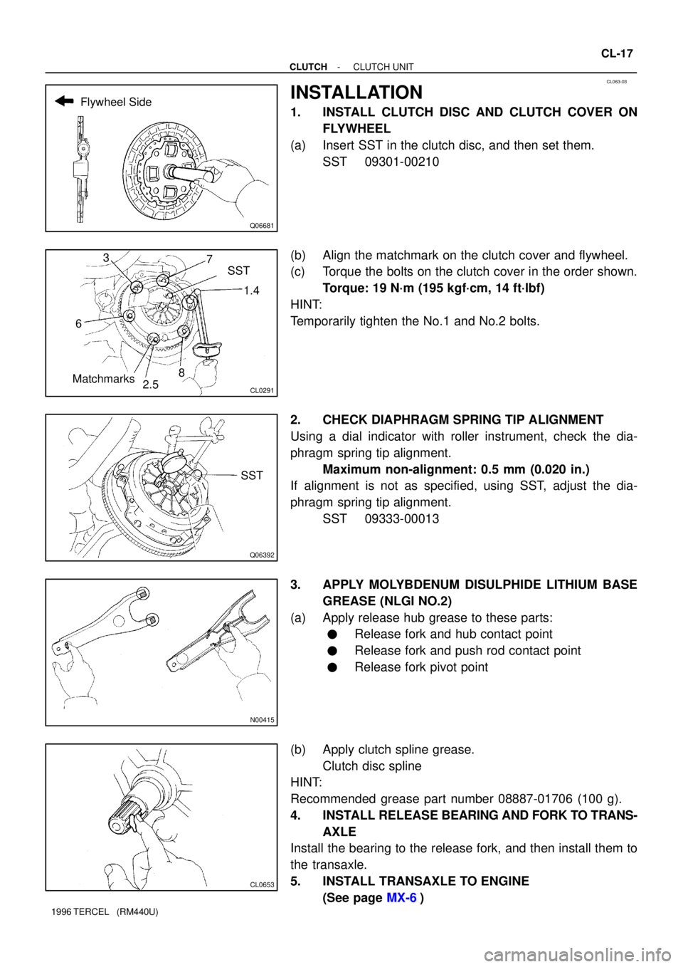
INSTALLATION
1. INSTALL CLUTCH DISC AND CLUTCH COVER ON
FLYWHEEL
(a) Insert SST in the clutch disc, and then set them.
SST 09301-00210
(b) Align the matchmark on the clutch cover and flywheel.
(c) Torque the bolts on the clutch cover in the order shown.
Torque: 19 N´m (195 kgf´cm, 14 ft´lbf)
HINT:
Temporarily tighten the No.1 and No.2 bolts.
2. CHECK DIAPHRAGM SPRING TIP ALIGNMENT
Using a dial indicator with roller instrument, check the dia-
phragm spring tip alignment.
Maximum non-alignment: 0.5 mm (0.020 in.)
If alignment is not as specified, using SST, adjust the dia-
phragm spring tip alignment.
SST 09333-00013
3. APPLY MOLYBDENUM DISULPHIDE LITHIUM BASE
GREASE (NLGI NO.2)
(a) Apply release hub grease to these parts:
�Release fork and hub contact point
�Release fork and push rod contact point
�Release fork pivot point
(b) Apply clutch spline grease.
Clutch disc spline
HINT:
Recommended grease part number 08887-01706 (100 g).
4. INSTALL RELEASE BEARING AND FORK TO TRANS-
AXLE
Install the bearing to the release fork, and then install them to
the transaxle.
5. INSTALL TRANSAXLE TO ENGINE
(See page MX-6)