Page 167 of 1202

TORQUE SPECIFICATION
Part tightenedN´mkgf´cmft´lbf
STEERING COLUMN
Steering support x Column tube5.45548 in.´lbf
Control")
SS0N2-05
- SERVICE SPECIFICATIONSSTEERING
SS-37
1996 TERCEL (RM440U)
TORQUE SPECIFICATION
Part tightenedN´mkgf´cmft´lbf
STEERING COLUMN
Steering support x Column tube5.45548 in.´lbf
Control valve shaft x Sliding yoke2526019
Steering main shaft x Sliding yoke2526019
Steering column assembly set nut2526019
Steering wheel set nut3435025
Steering wheel pad set screw8.89078 in.´lbf
PS VANE PUMP
Pressure port union x Front housing6970051
Suction port union x Front housing131309
Pressure feed tube x Pressure port union5455040
PS vane pump pulley set nut4344032
PS vane pump assembly set nut Bolt A4344032 PS vane um assembly set nut Bolt A
Bolt B
43
39
440
400
32
30
MANUAL STEERING GEAR
Pinion bearing adjusting screw lock nut for use with SST
for use without SST85
11 3871
1,15063
83
Rack guide spring cap lock nut for use with SST
for use without SST41
56419
57530
42
Rack x Rack end for use with SST
for use without SST43
59434
60031
43
Tie rod end lock nut4748035
Manual steering gear bracket x Body5859043
Pinion shaft x Sliding yoke2526019
Steering main shaft x Sliding yoke2526019
Column hole cover x Body4.95043 in.´lbf
PS GEAR
Cylinder end stopper5960043
Self-locking nut5960043
Rack housing cap5960043
Rack guide spring cap lock nut for use with SST
for use without SST31
44316
45023
33
Rack x Rack end for use with SST
for use without SST43
59434
60031
43
Tie rod end lock nut4748035
Turn pressure tube union nut for use with SST
for use without SST20
25203
25015
18
Air control valve2930022
PS gear bracket x Body5859043
Engine rear mount insulator Bolt A6465047 Engine rear mount insulator Bolt A
Bolt B
64
78
650
800
47
58
Engine rear mount bracket x Transaxle4849035
Front exhaust pipe x Exhaust manifold6263046
Front exhaust pipe clamp1919014
Front exhaust pipe x Oxygen sensor4445032
Page 482 of 1202
P20246
P20336
P20153
Ground Strap
P20285
M/T
P20002
A132L A/T EM-60
- ENGINE MECHANICALENGINE UNIT
1996 TERCEL (RM440U)
22. REMOVE ENGINE WITH TRANSAXLE FROM VE-
HICLE
(a) Install the No.1 engine hanger in the correct direction.
Part No.:
No.1 engine hanger 12281-11031
Bolt 91642-80825
(b) Attach the engine sling device to the engine hangers.
(c) Remove the rear engine mounting insulator through bolt.
(d) Remove the bolt and disconnect the ground strap.
(e) Remove the through bolt, 2 bolts, nut and RH engine
mounting insulator.
(f) M/T:
Remove the bolt and disconnect the ground strap.
(g) Remove the 5 bolts and LH engine mounting bracket.
(h) A132L A/T:
Remove the bolt and disconnect the ground strap.
(i) Remove the 5 bolts and LH engine mounting bracket.
Page 485 of 1202
P20246
P00352
P20285
M/T
P20866
A132L A/T
A242L A/T
- ENGINE MECHANICALENGINE UNIT
EM-63
1996 TERCEL (RM440U)
(d) Keep the engine level, and align RH and LH engine
mountings with the body bracket.
(e) Attach the RH engine mounting insulator to the mounting
bracket and body, and temporarily install the through bolt,
2 bolts and nut.
(f) Install the LH engine mounting bracket to the transaxle
and mounting insulator with the 5 bolts. Torque the bolts.
Torque:
Bracket to transaxle (bolt head: NT)
65 N´m (650 kgf´cm, 47 ft´lbf)
Bracket to insulator (bolt head: 7T)
49 N´m (490 kgf´cm, 35 ft´lbf)
(g) Connect the ground strap with the bolt.
Torque: 49 N´m (490 kgf´cm, 35 ft´lbf)
Page 714 of 1202
MX03N-01
- MANUAL TRANSAXLEMANUAL TRANSAXLE SYSTEM
MX-1
713 Author�: Date�:
1996 TERCEL (RM440U)
MANUAL TRANSAXLE SYSTEM
PRECAUTION
When working with FIPG material, you must observe the following items.
�Using a razor blade and gasket scraper, remove all the old FIPG material from the gasket sur-
faces.
�Thoroughly clean all components to remove all the loose material.
�Clean both sealing surfaces with a non-residue solvent.
�Apply FIPG in an approx. 1 mm (0.04 in.) wide bead along the sealing surface.
�Parts must be assembled within 10 minutes of application. Otherwise, the FIPG material must
be removed and reapplied.
Page 722 of 1202
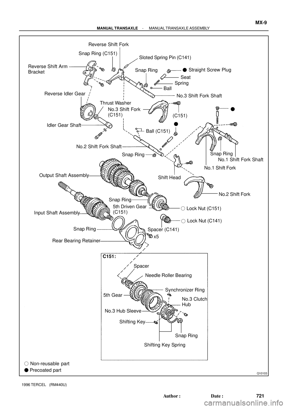
Q10103
Reverse Shift Arm
BracketReverse Shift Fork
Snap RingSnap Ring
Thrust Washer Reverse Idler Gear
Idler Gear Shaft
Ball (C151)Straight Screw Plug
�
BallSpringSeat
�
No.3 Shift Fork
(C151)�
No.2 Shift Fork Shaft
Output Shaft Assembly
Shift HeadNo.1 Shift Fork Shaft
No.1 Shift Fork
No.2 Shift Fork
Lock Nut (C141)
�
5th Driven Gear
(C151)
x5
Spacer Snap Ring
Rear Bearing Retainer
Needle Roller Bearing
5th GearSynchronizer Ring
No.3 Hub Sleeve
Shifting Key
� Non-reusable part
� Precoated partNo.3 Clutch
Hub
Snap Ring
Shifting Key SpringLock Nut (C151) �
Input Shaft AssemblySnap Ring
Spacer (C141)
No.3 Shift Fork Shaft Snap Ring (C151)
Snap RingSloted Spring Pin (C141)
(C151)
C151:
- MANUAL TRANSAXLEMANUAL TRANSAXLE ASSEMBLY
MX-9
721 Author�: Date�:
1996 TERCEL (RM440U)
Page 724 of 1202

9. REMOVE SHIFT AND SELECT LEVER SHAFT AS-
SEMBLY
(a) Remove the lock bolt.
Torque: 29 N´m")
Q06523
Lock Bolt
Q06512
Q06531
SST
- MANUAL TRANSAXLEMANUAL TRANSAXLE ASSEMBLY
MX-1 1
1996 TERCEL (RM440U)
9. REMOVE SHIFT AND SELECT LEVER SHAFT AS-
SEMBLY
(a) Remove the lock bolt.
Torque: 29 N´m (300 kgf´cm, 22 ft´lbf)
(b) Remove the 4 bolts and pull out the shift and select lever
shaft assembly with the gasket.
Sealant:
Part No.08833-00080, THREE BOND 1344, LOCTITE
242 or equivalent
Torque: 20 N´m (200 kgf´cm, 14 ft´lbf)
10. REMOVE LOCK NUT
(a) Engage the gear double meshing.
(b) Using a hammer and chisel, loosen the staked part of the
nut.
(c) Remove the lock nut.
Torque: 118 N´m (1,200 kgf´cm, 87 ft´lbf)
(d) C141:
Remove the spacer.
(e) Disengage the gear double meshing.
11. C151:
REMOVE NO.3 HUB SLEEVE AND NO.3 SHIFT FORK
(a) Remove the bolt from the No.3 shift fork.
Torque: 16 N´m (160 kgf´cm, 12 ft´lbf)
(b) Remove the No.3 hub sleeve and shift fork.
12. C151:
REMOVE NO.3 CLUTCH HUB AND 5TH GEAR
(a) Using 2 screwdrivers and a hammer, tap out the snap
ring.
HINT:
Select a snap ring that will allow minimum axial play.
MarkThickness mm (in.)MarkThickness mm (in.)
A2.25 (0.0886)E2.49 (0.0980)
B2.31 (0.0909)F2.55 (0.1004)
C2.37 (0.0933)G2.61 (0.1028)
D2.43 (0.0957)--
(b) Using SST, remove the 5th gear, No.3 clutch hub, syn-
chronizer ring, needle roller bearings and spacer.
SST 09950-40010
Page 757 of 1202

Z13623
RPMidle
AT5867Drain plug Filler plug
MT0613
Filler Hole
Fluid Level
0 - 5 mm
e
Z15674
Adjusting Nut
Outer Cable Rubber Boot
Cable Stopper0 - 1 mm
BE1485
8 423
5 761
9 AX-4
- AUTOMATIC TRANSAXLE (A132L)AUTOMATIC TRANSAXLE SYSTEM (A132L)
1996 TERCEL (RM440U)
(4) Start the engine and shift the selector into all posi-
tions from the P position through the L position and
then shift it into the P position.
(5) With the engine idling, check the fluid level. Add the
fluid up to the COOL level on the dipstick.
(6) Check the fluid level at the normal operating tem-
perature 70 - 80 °C (158 - 176 °F) and add as nec-
essary.
NOTICE:
Do not overfill.
(d) If necessary, replace the differential fluid.
(1) Using a hexagon wrench, remove the drain plug
and drain the fluid.
(2) Using a hexagon wrench, install the drain plug se-
curely.
(3) Remove the filler plug.
(4) Add new fluid until it begins to run out of the filler
hole.
Fluid type: ATF D-ll or DEXRON®lll (DEXRON®ll)
Capacity: 1.4 liters (1.5 US qts, 1.2 lmp.qts)
(e) Check the differential fluid level.
Remove the filler plug and check the differential fluid lev-
el.
(f) Inspect and adjust the throttle cable.
(1) Depress the accelerator pedal all the way and
check that the throttle valve opens fully.
HINT:
If the throttle valve does not open fully, adjust the accelerator
link.
(2) Fully depress the accelerator.
(3) Loosen the adjustment nuts.
(4) Adjust the outer cable so that the distance between
the end of the boot and the stopper on the cable is
the standard.
Standard boot and cable stopper distance:
0 - 1 mm (0 - 0.04 in.)
(5) Tighten the adjusting nuts.
(6) Recheck the adjustment.
(g) Inspect the park/neutral position switch.
(1) Remove the park/neutral position switch
(See page AX-15).
Page 758 of 1202
AUTOMATIC TRANSAXLE SYSTEM (A132L)
AX-5
1996 TERCEL (RM440U)
(2) Using an ohmmeter, check continuity between each
terminal shown below w")
AT8103
Neutral Basic Line
Groove
- AUTOMATIC TRANSAXLE (A132L)AUTOMATIC TRANSAXLE SYSTEM (A132L)
AX-5
1996 TERCEL (RM440U)
(2) Using an ohmmeter, check continuity between each
terminal shown below when the shift lever is put in
each position.
(h) Adjust the shift control cable.
(1) Remove the engine under cover.
(2) Loosen the nut on the control shaft lever.
(3) Push the control shaft lever fully toward the right
side of the vehicle.
(4) Return the lever 2 notches to the NEUTRAL posi-
tion.
(5) Set the shift lever to the N position.
(6) While holding the lever lightly toward the ºRº posi-
tion side, tighten the swivel nut.
(i) Adjust the park/neutral position switch.
If the engine will start with the shift selector in any position other
than the N or P position, adjustment is required.
(1) Loosen the park/neutral position switch bolts and
set the shift selector to the N position.
(2) Align the groove with neutral basic line.
(3) Hold the switch in the position and tighten the bolts.
Torque: 5.4 N´m (55 kgf´cm, 48 in.´lbf)
(j) Inspect the idle speed.
Idle speed:
750 ± 50 rpm (In the N position and A/C OFF)
3. MEASURE STALL TEST
The object of this test is to check the overall performance of the transaxle and the engine by measuring the
maximum engine speeds in the D and R positions.
NOTICE:
�Do the test at normal operating fluid temperature 50 - 80°C (122 - 176 °F).
�Do not continuously run this test longer than 5 seconds.
(1) Check the front and rear wheels.
(2) Connect the tachometer to the engine.
(3) Fully apply the parking brake.

22. REMOVE ENGINE WITH TRANSAXLE FROM VE-
HICLE
(a) Install the No.1 engine ha")

(d) Keep the engine level, and align RH and LH engine
mountings with the body bracket.")