Page 884 of 1202
BR4387
BR3027
SST
BR0370
- BRAKEREAR DRUM BRAKE
BR-31
1996 TERCEL (RM440U)
(d) Using pliers, disconnect the parking brake cable from the
parking brake lever and remove the rear shoe.
6. REMOVE AUTOMATIC ADJUSTING LEVER AND
PARKING BRAKE LEVER
(a) Remove the E-ring.
(b) Remove the automatic adjusting lever.
(c) Remove the C-washer.
(d) Remove the parking brake lever.
7. REMOVE WHEEL CYLINDER
(a) Using SST, disconnect the brake line. Use a container to
catch the brake fluid.
SST 09751-3601 1
Torque: 15 N´m (155 kgf´cm, 11 ft´lbf)
(b) Remove the 2 bolts and the wheel cylinder.
Torque: 10 N´m (100 kgf´cm, 7 ft´lbf)
8. DISASSEMBLE WHEEL CYLINDER
Remove the these parts from the wheel cylinder.
�2 boots
�2 pistons
�2 piston cups
�Spring
Page 887 of 1202
BR0RZ-06
R04666
SSTSST BR-34
- BRAKEPROPORTIONING VALVE (P VALVE)
908 Author�: Date�:
1996 TERCEL (RM440U)
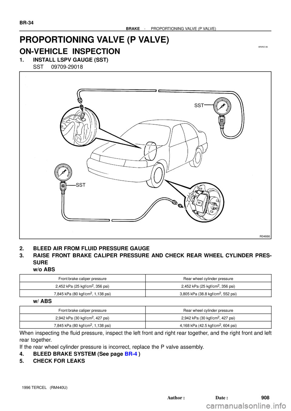
PROPORTIONING VALVE (P VALVE)
ON-VEHICLE INSPECTION
1. INSTALL LSPV GAUGE (SST)
SST 09709-29018
2. BLEED AIR FROM FLUID PRESSURE GAUGE
3. RAISE FRONT BRAKE CALIPER PRESSURE AND CHECK REAR WHEEL CYLINDER PRES-
SURE
w/o ABS
Front brake caliper pressureRear wheel cylinder pressure
2,452 kPa (25 kgf/cm2, 356 psi)2,452 kPa (25 kgf/cm2, 356 psi)
7,845 kPa (80 kgf/cm2, 1,138 psi)3,805 kPa (38.8 kgf/cm2, 552 psi)
w/ ABS
Front brake caliper pressureRear wheel cylinder pressure
2,942 kPa (30 kgf/cm2, 427 psi)2,942 kPa (30 kgf/cm2, 427 psi)
7,845 kPa (80 kgf/cm2, 1,138 psi)4,168 kPa (42.5 kgf/cm2, 604 psi)
When inspecting the fluid pressure, inspect the left front and right rear together, and the right front and left
rear together.
If the rear wheel cylinder pressure is incorrect, replace the P valve assembly.
4. BLEED BRAKE SYSTEM (See page BR-4)
5. CHECK FOR LEAKS
Page 916 of 1202

INSPECTION
NOTICE:
When using a vise do not overtighten it.
1. INSPECT STEERING LOCK OPERATION
Check that the steering lock me")
SR17T-02
- STEERINGNON-TIL T STEERING COLUMN
SR-17
1996 TERCEL (RM440U)
INSPECTION
NOTICE:
When using a vise do not overtighten it.
1. INSPECT STEERING LOCK OPERATION
Check that the steering lock mechanism operates properly.
2. IF NECESSARY, REPLACE KEY CYLINDER
(a) Place the ignition key at the ACC position.
(b) Push down the stop pin with a thin rod, and pull out the
key cylinder.
(c) Install a new cylinder.
HINT:
Make sure the ignition key is at the ACC position.
3. INSPECT IGNITION SWITCH (See page BE-1 1)
4. IF NECESSARY, REPLACE IGNITION SWITCH
(a) Remove the 2 screws.
(b) Install a new ignition switch with the 2 screws.
5. INSPECT KEY UNLOCK WARNING SWITCH
(See page BE-1 1)
6. IF NECESSARY, REPLACE KEY UNLOCK WARNING
SWITCH
(a) Remove the 2 screws.
(b) Install a new switch with the 2 screws.
7. A/T:
INSPECT KEY INTERLOCK SOLENOID
A132L A/T: (See page AX-24)
A242L A/T: (See page AX-28)
8. A/T:
IF NECESSARY, REPLACE KEY INTERLOCK SOLE-
NOID
(a) Remove the 2 screws.
(b) Install a new solenoid with the 2 screws.
9. INSPECT BEARING
Check the bearing rotation condition and check for abnormal
noise.
If the bearing is worn or damaged, replace the column tube.
Page 950 of 1202
SR4297
SST
R06217
SST
Pin
Pin
R11075
SST
R11056
SST
- STEERINGPOWER STEERING GEAR
SR-51
1996 TERCEL (RM440U)
11. REMOVE SELF-LOCKING NUT
Using SST, stop the control valve rotating and remove the nut.
SST 09616-00010
12. REMOVE CONTROL VALVE ASSEMBLY WITH OIL
SEAL AND BEARING
(a) Using snap ring pliers, remove the snap ring from the rack
housing.
(b) Using SST, remove the valve assembly with the oil seal
and bearing.
SST 09613-12010
NOTICE:
Never attempt to tap out the control valve as this would
damage it.
(c) Remove the oil seal from the valve assembly.
(d) Using SST, remove the bearing from the valve assembly.
SST 09950-40010 (09951-04010, 09952-04010,
09953-04020, 09954-04010, 09955-04050,
09957-04010, 09958-04010)
13. REMOVE BEARING
Using a brass bar and hammer, tap out the bearing from the
rack housing.
14. REMOVE CYLINDER END STOPPER AND BUSHING
Using SST, remove the stopper and bushing.
SST 09631-20090
Page 952 of 1202

INSPECTION
NO")
SR0L0-02
R10072
Dial Indicator
R11358
Cylinder Gauge
Micrometer
Bushing
R11357
BushingSST Steel
Plate
R11359
Brass Bar
Oil Seal
- STEERINGPOWER STEERING GEAR
SR-53
1996 TERCEL (RM440U)
INSPECTION
NOTICE:
When using a vise, do not overtighten it.
1. INSPECT STEERING RACK
Using a dial indicator, check the rack for runout and teeth wear
and damage.
Maximum runout: 0.30 mm (0.0118 in.)
2. MEASURE OIL CLEARANCE BETWEEN CONTROL
VALVE ASSEMBLY AND BUSHING
Using a micrometer and a cylinder gauge, measure the oil clear-
ance.
Standard clearance:
0.050 - 0.083 mm (0.00197 - 0.00327 in.)
Maximum clearance: 0.125 mm (0.00492 in.)
3. IF NECESSARY, REPLACE BUSHING AND OIL SEAL
(a) Using SST and 2 steel plates, remove the bushing from
the rack housing.
SST 09612-65014 (09612-01030)
NOTICE:
�As shown, from the opposite side of SST confirm that
its claw is firmly caught on the bushing.
�Be careful not to damage the rack housing.
(b) Using a brass bar and a hammer, remove the oil seal from
the rack housing.
NOTICE:
Be careful not to damage the rack housing.
(c) Coat a new oil seal lip with power steering fluid.
(d) Using a socket wrench (24 mm), extension bar and ham-
mer, press in the oil seal.
NOTICE:
Make sure to install the oil seal facing the correct direction.
Page 956 of 1202

4. INSTALL OIL SEAL
(a) Coat a new oil seal lip with power steering fluid.
(b) To prevent oil seal li")
Z03128
Vinyl Tape
R11057
SST
SR4264
SST
- STEERINGPOWER STEERING GEAR
SR-57
1996 TERCEL (RM440U)
4. INSTALL OIL SEAL
(a) Coat a new oil seal lip with power steering fluid.
(b) To prevent oil seal lip damage, wind vinyl tape on the
steering rack end, and apply power steering fluid.
(c) Install the oil seal by pushing it into the rack housing, with-
out tilting.
NOTICE:
Make sure to install the oil seal facing the correct direction.
5. INSTALL BUSHING AND CYLINDER END STOPPER
(a) Install a new bushing to the stopper.
(b) Using SST, torque the stopper.
SST 09631-20090
Torque: 59 N´m (600 kgf´cm, 43 ft´lbf)
(c) Using a punch and a hammer, stake the stopper and rack
housing.
6. AIR TIGHTNESS TEST
(a) Install SST to the rack housing.
SST 09631-12071
NOTICE:
Do not install union seats.
(b) Apply 53 kPa (400 mmHg, 15.75 in.Hg) of vacuum for
about 30 seconds.
(c) Check that there is no change in the vacuum.
If there is change in the vacuum, check the installation of the oil
seals.
7. INSTALL CONTROL VALVE ASSEMBLY
(a) Coat the teflon rings with power steering fluid.
(b) Push the valve assembly into the rack housing.
Page 1080 of 1202
BO1HB-03
N15574
2-Door:
� Precoated partDoor Glass Run
Door Belt Moulding
Outside Handle
Door Lock Cylinder
Door Glass
Rear View Mirror
Inner Cover
Door Hinge
Door Hinge Control Link Door Lock
Front Lower Frame
Service Hole Cover
Grommet
Inside Handle
Door Trim
Plate
Snap Ring Armrest Door Trim
Armrest
Cover w/ Power Window:w/ Power Window: w/ Power Door Lock:
�
Speaker
Window Regulator Door Lock
Door CheckerWindow Regulator
Armrest Panel
Regulator Handle
- BODYFRONT DOOR
BO-9
1103 Author�: Date�:
1996 TERCEL (RM440U)
FRONT DOOR
COMPONENTS
Page 1081 of 1202
N15573
4-Door:
Door Glass RunFront Door Belt Moulding
Outside Handle Door Lock Cylinder
Door Glass
Rear View Mirror
Inner Cover
Door Hinge Control Link Door Lock
Front Lower
Frame
Service Hole Cover
Window Regulator
Inside Handle
Snap Ring Armrest Door Trim
Armrest Cover w/ Power Window:
w/ Power Window: w/ Power Door Lock:
Speaker
Plate Door Trim
� Precoated partRegulator HandleGrommetDoor Hinge Door Checker Door Lock
Window Regulator�
Armrest Panel
BO-10
- BODYFRONT DOOR
1104 Author�: Date�:
1996 TERCEL (RM440U)

(d) Using pliers, disconnect the parking brake cable from the
parking brake lever and remove the rear shoe.
6. REMOVE AUTOM")

11. REMOVE SELF-LOCKING NUT
Using SST, stop the control valve rotating and remove the nut")