Page 1728 of 2062

Downloaded from www.Manualslib.com manuals search engine R07644Red Mark
R07660
Torx ScrewScrew Case
− STEERINGNON−TILT STEERING COLUMN
SR−21
1996 TOYOTA T100 (RM449U)
9. INSTALL COMBINATION SWITCH WITH SPIRAL
CABLE
(a) Install the 4 screws.
(b) Connect the airbag connector.
(c) Connect the connectors.
(d) Install the 2 screws.
10. INSTALL DUCT HEATER TO REGISTER NO.2
Install the screw.
11. INSTALL LOWER FINISH PANEL NO.1
(a) Install the lock nuts and light control rheostat.
(b) Tighten the 4 panel set bolts.
(c) Install the cowl side trim and clip.
(d) Install the front door scuff plate with the 4 screws.
(e) Install the engine hood release lever with the 2 screws.
12. A/T:
INSTALL UPPER AND LOWER COLUMN COVERS
Install the 6 screws.
13. M/T:
INSTALL UPPER AND LOWER COLUMN COVERS
Install the 7 screws.
14. CENTER SPIRAL CABLE
(a) Check that the front wheels are facing straight ahead.
(b) Turn the spiral counterclockwise by hand until it becomes
harder to turn the cable.
(c) Then turn the spiral cable clockwise about 3 turns to align
the red mark.
HINT:
The spiral cable turns clockwise about 3 turns to either left or
right of the center.
15. INSTALL STEERING WHEEL
(a) Align the matchmarks on the wheel and main shaft.
(b) Torque the set nut.
Torque: 35 N·m (360 kgf·cm, 26 ft·lbf)
(c) Connect the connector.
16. INSTALL STEERING WHEEL PAD
NOTICE:
�Make sure the wheel pad is installed to the specified
torque.
�If the wheel pad has been dropped, or there are
cracks, dents in the case or connector, replace the
wheel pad with a new one.
�When installing the wheel pad, take care that the wir-
ings do not interfere with other parts and are not
pinched between other parts.
Page 1729 of 2062
Downloaded from www.Manualslib.com manuals search engine SR−22
− STEERINGNON−TILT STEERING COLUMN
1996 TOYOTA T100 (RM449U)
(a) Connect the airbag connector.
(b) Install the wheel pad after confirming that the circumfer-
ence groove of the torx screws is caught on the screw
case.
(c) Using a torx wrench, torque the 2 screws.
Torque: 9.0 N·m (90 kgf·cm, 78 in.·lbf)
17. CHECK STEERING WHEEL CENTER POINT
Page 1730 of 2062
Downloaded from www.Manualslib.com manuals search engine W03156
Column UpperParking Lock Cable
Torx Screw
Steering Wheel Lower
No.2 Cover
Control Shaft AssemblySteering Wheel
Steering Wheel
Steering Wheel Lower
No.3 Cover
Torx Screw
Combination Switch
(w/ Spiral Cable)
Column lower Cover
Light Control Rheostat
Front Door Scuff Steering Column
Assembly Control Shaft
� Locking
Column Hole
Sliding w/ Shaft York
Sub−Assembly
Lower Finish Panel No.1
Engine Hood Release Intermediate
Shaft Assembly
Register No.2 Duct Heater toPlatePad
Lever Cover
Wire
Cover
Lever AT:
For 2WD
Intermediate
Shaft Assembly
Cowl Side Trimx6
�Non−reusable part35 (360, 26)
9.0 (90, 78 in.·lbf)
35 (360, 26)
35 (360, 26)
35 (360, 26)
35 (360, 26)
: Specified torque
N·m (kgf·cm, ft·lbf)
25 (260, 19)
25 (260, 19)
9.0 (90, 78 in.·lbf)
SR07C−01
− STEERINGTILT STEERING COLUMN
SR−23
1697 Author�: Date�:
1996 TOYOTA T100 (RM449U)
TILT STEERING COLUMN
COMPONENTS
Page 1731 of 2062
Downloaded from www.Manualslib.com manuals search engine W03157
Cover
Pad
Plate
Lever MT:
For 2WDSteering Column AssemblySteering Wheel Steering Wheel
Steering Wheel Lower
No.3 Cover
Torx Screw
Combination Switch
(w/ Spiral Cable)
Column Lower Cover
Light Control Rheostat
Front Door Scuff x7
Sliding w/ Shaft York
Sub−Assembly
Lower Finish Panel No.1 Column Hole CoverColumn Upper
Torx Screw
Steering Wheel Lower
No.2 Cover
Intermediate
Engine Hood Release Shaft Assembly
Duct Heater to
Register No.2
Intermediate
Shaft Assembly
Cowl Side Trim 9.0 (90, 78 in.·lbf)
35 (360, 26)
: Specified torque
N·m (kgf·cm, ft·lbf)
25 (260, 19)
9.0 (90, 78 in.·lbf)
35 (360, 26)
35 (360, 26)
35 (360, 26)
SR−24
− STEERINGTILT STEERING COLUMN
1698 Author�: Date�:
1996 TOYOTA T100 (RM449U)
Page 1777 of 2062

Downloaded from www.Manualslib.com manuals search engine R04620
R04621
28−8°
2−5 mm
(0.08−0.20in.)
R15216
SST
Fulcrum
Length SR−70
− STEERINGPOWER STEERING GEAR (2WD)
1996 TOYOTA T100 (RM449U)
17. INSTALL RH AND LH RACK BOOTS, CLAMPS AND
CLIPS
(a) Make sure that the tube hole is not clogged with grease.
HINT:
If the tube hole is clogged, the pressure inside the boot will
change after it is assembled and the steering wheel turned.
(b) Install the boot.
NOTICE:
Be careful not to damage or twist the boot.
(c) Tighten the clamp and clip, as shown in the illustration.
18. INSTALL RH AND LH TIE ROD ENDS AND LOCK NUTS
(a) Screw the lock nut and tie rod end onto the rack end until
the matchmarks are aligned.
(b) After adjusting toe−in, torque the lock nut (See page
SA−7).
Torque: 56 N·m (570 kgf·cm, 41 ft·lbf)
19. INSTALL 2 TURN PRESSURE TUBES
(a) Coat 2 new O−rings with power steering fluid and install
them to the tube.
(b) Using SST, install and torque the tube.
SST 09633−00020
Torque: 10 N·m (102 kgf·cm, 7 ft·lbf)
HINT:
�Use a torque wrench with a fulcrum length of 250 mm
(9.84 in.).
�This torque value is effective in case that SST is parallel
to a torque wrench.
(c) Install the clamp plate with the bolt.
Page 1778 of 2062

Downloaded from www.Manualslib.com manuals search engine SR07Z−01
R15251
SST
Fulcum Length
− STEERINGPOWER STEERING GEAR (2WD)
SR−71
1996 TOYOTA T100 (RM449U)
INSTALLATION
1. INSTALL PS GEAR ASSEMBLY
Torque: 88 N·m (900 kgf·cm, 65 ft·lbf)
Torque the 2 gear assembly set bolts and nut.
2. INSTALL MOUNT BRACKET AND GROMMET
(a) Install the grommet and mount bracket to the PS gear as-
sembly.
(b) Torque the 2 bolts.
Torque: 88 N·m (900 kgf·cm, 65 ft·lbf)
3. CONNECT PRESSURE FEED TUBE AND INSTALL
RETRUN TUBE
(a) Coat a new O−ring with power steering fluid and install it
to the tube.
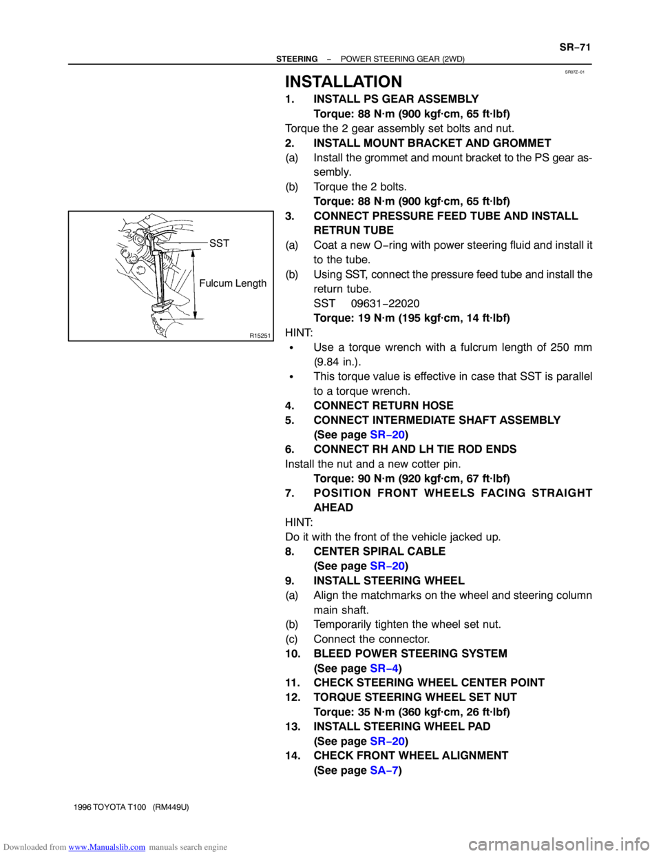
(b) Using SST, connect the pressure feed tube and install the
return tube.
SST 09631−22020
Torque: 19 N·m (195 kgf·cm, 14 ft·lbf)
HINT:
�Use a torque wrench with a fulcrum length of 250 mm
(9.84 in.).
�This torque value is effective in case that SST is parallel
to a torque wrench.
4. CONNECT RETURN HOSE
5. CONNECT INTERMEDIATE SHAFT ASSEMBLY
(See page SR−20)
6. CONNECT RH AND LH TIE ROD ENDS
Install the nut and a new cotter pin.
Torque: 90 N·m (920 kgf·cm, 67 ft·lbf)
7. POSITION FRONT WHEELS FACING STRAIGHT
AHEAD
HINT:
Do it with the front of the vehicle jacked up.
8. CENTER SPIRAL CABLE
(See page SR−20)
9. INSTALL STEERING WHEEL
(a) Align the matchmarks on the wheel and steering column
main shaft.
(b) Temporarily tighten the wheel set nut.
(c) Connect the connector.
10. BLEED POWER STEERING SYSTEM
(See page SR−4)
11. CHECK STEERING WHEEL CENTER POINT
12. TORQUE STEERING WHEEL SET NUT
Torque: 35 N·m (360 kgf·cm, 26 ft·lbf)
13. INSTALL STEERING WHEEL PAD
(See page SR−20)
14. CHECK FRONT WHEEL ALIGNMENT
(See page SA−7)
Page 1790 of 2062

Downloaded from www.Manualslib.com manuals search engine SR085−01
R15509
Fulcrum
Length
SST
SR2922
Alignment Marks
− STEERINGPOWER STEERING GEAR (4WD)
SR−83
1996 TOYOTA T100 (RM449U)
INSTALLATION
1. INSTALL PS GEAR ASSEMBLY
Install the 3 bolts, washers and nuts.
Torque: 142 N·m (1,450 kgf·cm, 105 ft·lbf)
2. CONNECT INTERMEDIATE SHAFT ASSEMBLY
(See page SR−20)
3. CONNECT PRESSURE FEED TUBE AND RETURN
TUBE
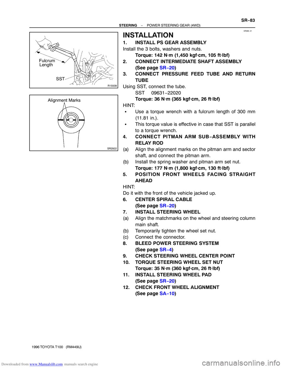
Using SST, connect the tube.
SST 09631−22020
Torque: 36 N·m (365 kgf·cm, 26 ft·lbf)
HINT:
�Use a torque wrench with a fulcrum length of 300 mm
(11.81 in.).
�This torque value is effective in case that SST is parallel
to a torque wrench.
4. CONNECT PITMAN ARM SUB−ASSEMBLY WITH
RELAY ROD
(a) Align the alignment marks on the pitman arm and sector
shaft, and connect the pitman arm.
(b) Install the spring washer and pitman arm set nut.
Torque: 177 N·m (1,800 kgf·cm, 130 ft·lbf)
5. POSITION FRONT WHEELS FACING STRAIGHT
AHEAD
HINT:
Do it with the front of the vehicle jacked up.
6. CENTER SPIRAL CABLE
(See page SR−20)
7. INSTALL STEERING WHEEL
(a) Align the matchmarks on the wheel and steering column
main shaft.
(b) Temporarily tighten the wheel set nut.
(c) Connect the connector.
8. BLEED POWER STEERING SYSTEM
(See page SR−4)
9. CHECK STEERING WHEEL CENTER POINT
10. TORQUE STEERING WHEEL SET NUT
Torque: 35 N·m (360 kgf·cm, 26 ft·lbf)
11. INSTALL STEERING WHEEL PAD
(See page SR−20)
12. CHECK FRONT WHEEL ALIGNMENT
(See page SA−10)
Page 1795 of 2062
Downloaded from www.Manualslib.com manuals search engine R04469
Alignment
Marks SR−88
− STEERINGSTEERING LINKAGE
1996 TOYOTA T100 (RM449U)
5. INSTALL PITMAN ARM
(a) Align the alignment marks on the pitman arm and the
cross shaft.
(b) Install the spring washer and pitman arm set nut.
Torque: 177 N·m (1,800 kgf·cm, 130 ft·lbf)
(c) Connect the pitman arm to the relay rod.
(d) Install the nut and a new cotter pin.
Torque: 90 N·m (920 kgf·cm, 67 ft·lbf)
6. INSTALL ENGINE UNDER COVER
Tighten the 4 bolts.
7. CHECK FRONT WHEEL ALIGNMENT
(See page SA−10)