Page 1369 of 2062
Downloaded from www.Manualslib.com manuals search engine AT01U−01
− AUTOMATIC TRANSMISSIONAUTOMATIC TRANSMISSION SYSTEM
AT−1
1342 Author�: Date�:
1996 TOYOTA T100 (RM449U)
AUTOMATIC TRANSMISSION SYSTEM
PRECAUTION
If the vehicle is equipped with a mobile communication system, refer to the precautions in the IN section.
Page 1370 of 2062

Downloaded from www.Manualslib.com manuals search engine AT007−04
V07130
Shift lever position
P
N R
D
L 2C0Gear position C1C2B0F0F1F2B1B2B3
ReverseParking
Neutral
1st
2nd
3rd
O/D
1st
2nd�
1st
*
2 2nd *
1 3rd�
� �
�
�
�
� �
�
�
��
�
�
�
�
�
�
�
��
�
�
��
�
��� � � �
��
��� � � � �� �
�
�
�� � �
*
1: Down−shift only in the 2 position and 3rd gear � no up−shift.
*2: Down−shift only in the L position and 2nd gear � no up−shift.� ... Operating O/D Direct Clutch (C
0)
O/D Input Shaft
O/D Brake (B0)
2nd Coast Brake (B1)
Direct
Clutch (C
2)
Forward Clutch (C1)
2nd Brake (B
2)
1st & Reverse
Brake (B
3)
Rear Planetary carrier
Rear Planetary Ring Gear
Input ShaftOutput Shaft
Front & Rear Planetary Sun Gear
No.2 One−Way Clutch (F2)
No.1 One−Wa y
Clutch (F
1)
Front Planetary
Ring Gear
Front Planetary
Carrier
O/D Planetary
Ring Gear
O/D Planetary
Carrier
O/D Planetary
Sun GearO/D One−Wa y
Clutch (F
0)
AT−2
− AUTOMATIC TRANSMISSIONAUTOMATIC TRANSMISSION SYSTEM
1996 TOYOTA T100 (RM449U)
OPERATION
Page 1371 of 2062
Downloaded from www.Manualslib.com manuals search engine AT022−06
OR0004
SST
OR0005
SST
− AUTOMATIC TRANSMISSIONEXTENSION HOUSING OIL SEAL (A340E)
AT−3
1344 Author�: Date�:
1996 TOYOTA T100 (RM449U)
EXTENSION HOUSING OIL SEAL
(A340E)
ON−VEHICLE REPAIR
1. REMOVE PROPELLER SHAFT (See page PR−3)
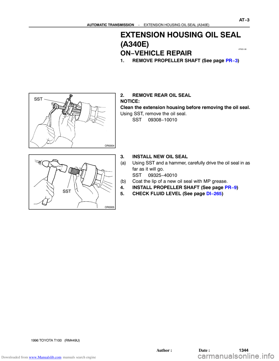
2. REMOVE REAR OIL SEAL
NOTICE:
Clean the extension housing before removing the oil seal.
Using SST, remove the oil seal.
SST 09308−10010
3. INSTALL NEW OIL SEAL
(a) Using SST and a hammer, carefully drive the oil seal in as
far as it will go.
SST 09325−40010
(b) Coat the lip of a new oil seal with MP grease.
4. INSTALL PROPELLER SHAFT (See page PR−9)
5. CHECK FLUID LEVEL (See page DI−265)
Page 1372 of 2062
Downloaded from www.Manualslib.com manuals search engine AT023−02
Q06961
3RZ−FE
Z14780
5VZ−FE
Q06981
AT−4
− AUTOMATIC TRANSMISSIONSENSOR ROTOR (A340E)
1345 Author�: Date�:
1996 TOYOTA T100 (RM449U)
SENSOR ROTOR (A340E)
ON−VEHICLE REPAIR
1. REMOVE PROPELLER SHAFT (See page PR−3)
2. DISCONNECT SPEEDOMETER CABLE AND RE-
MOVE SPEEDOMETER DRIVEN GEAR
(See page AT−8)
3. REMOVE NO.2 VEHICLE SPEED SENSOR
(See page AT−10)
4. JACK UP TRANSMISSION SLIGHTLY
Securely support the transmission on a transmission jack. Lift
the transmission slightly from the crossmember.
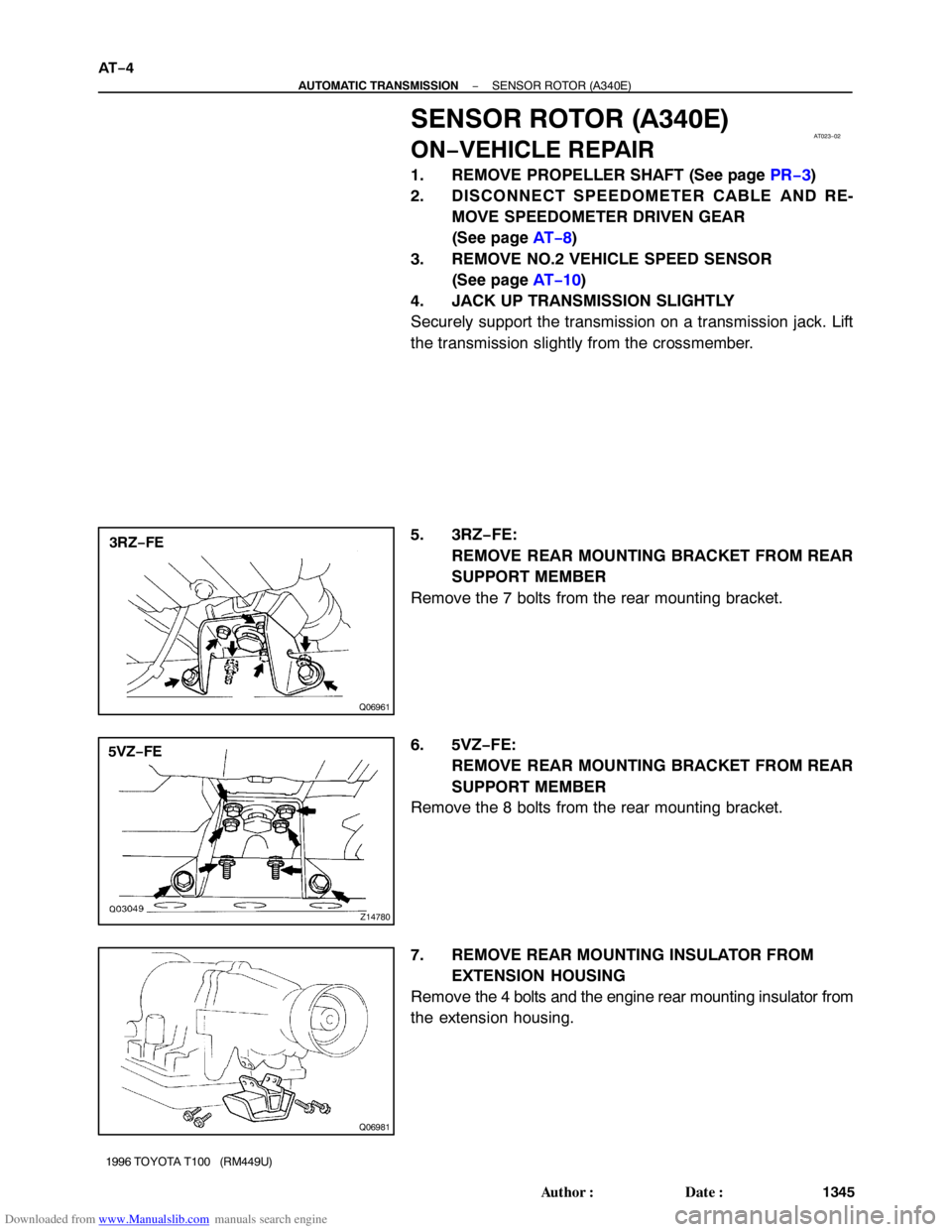
5. 3RZ−FE:
REMOVE REAR MOUNTING BRACKET FROM REAR
SUPPORT MEMBER
Remove the 7 bolts from the rear mounting bracket.
6. 5VZ−FE:
REMOVE REAR MOUNTING BRACKET FROM REAR
SUPPORT MEMBER
Remove the 8 bolts from the rear mounting bracket.
7. REMOVE REAR MOUNTING INSULATOR FROM
EXTENSION HOUSING
Remove the 4 bolts and the engine rear mounting insulator from
the extension housing.
Page 1373 of 2062
Downloaded from www.Manualslib.com manuals search engine AT4357
Q00627
Q00626
3RZ−FE
Q07626
5VZ−FE
Q00626
3RZ−FE
− AUTOMATIC TRANSMISSIONSENSOR ROTOR (A340E)
AT−5
1346 Author�: Date�:
1996 TOYOTA T100 (RM449U)
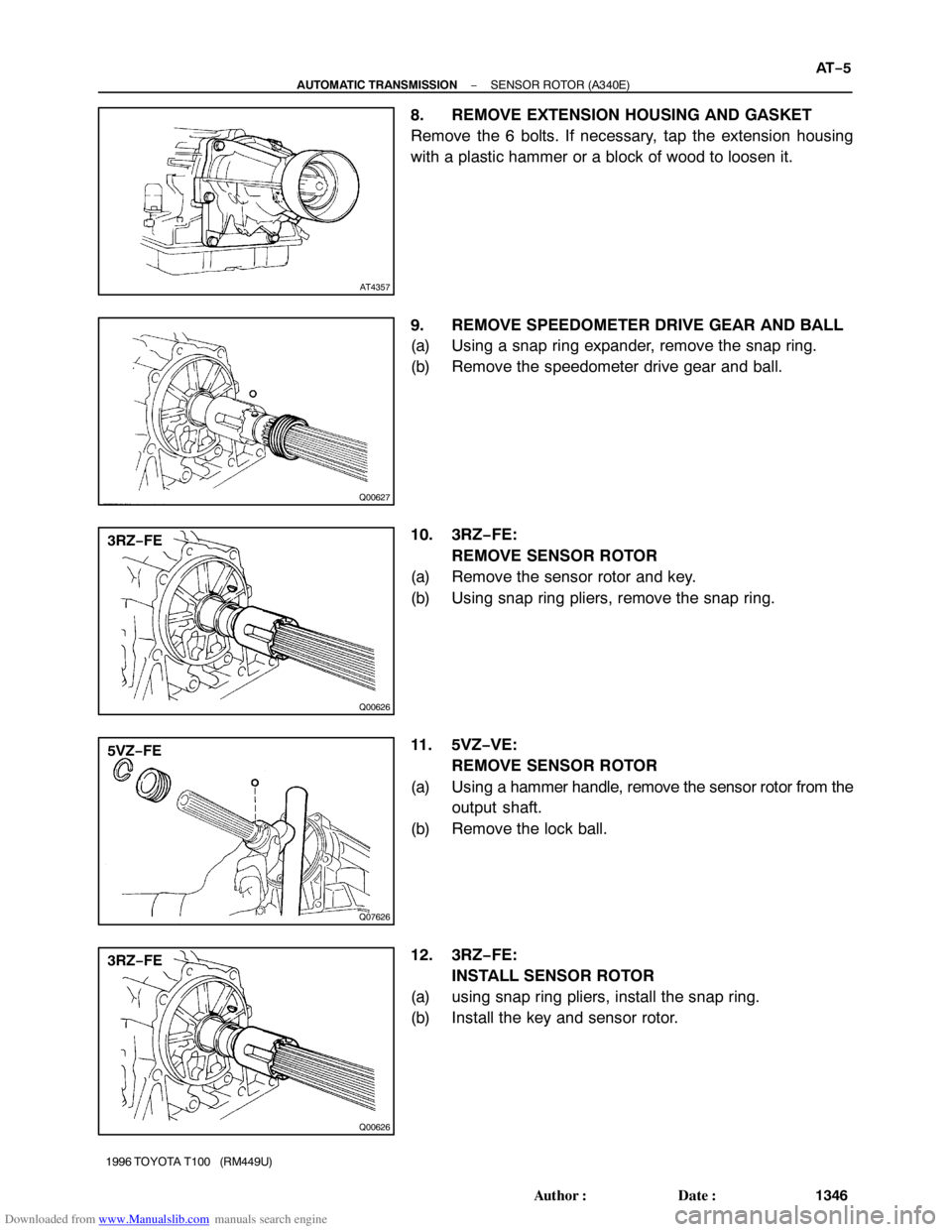
8. REMOVE EXTENSION HOUSING AND GASKET
Remove the 6 bolts. If necessary, tap the extension housing
with a plastic hammer or a block of wood to loosen it.
9. REMOVE SPEEDOMETER DRIVE GEAR AND BALL
(a) Using a snap ring expander, remove the snap ring.
(b) Remove the speedometer drive gear and ball.
10. 3RZ−FE:
REMOVE SENSOR ROTOR
(a) Remove the sensor rotor and key.
(b) Using snap ring pliers, remove the snap ring.
11. 5VZ−VE:
REMOVE SENSOR ROTOR
(a) Using a hammer handle, remove the sensor rotor from the
output shaft.
(b) Remove the lock ball.
12. 3RZ−FE:
INSTALL SENSOR ROTOR
(a) using snap ring pliers, install the snap ring.
(b) Install the key and sensor rotor.
Page 1374 of 2062
Downloaded from www.Manualslib.com manuals search engine D00779
5VZ−FE
D00780
AT4357
Q06981
AT−6
− AUTOMATIC TRANSMISSIONSENSOR ROTOR (A340E)
1347 Author�: Date�:
1996 TOYOTA T100 (RM449U)
13. 5VZ−FE:
INSTALL SENSOR ROTOR
Install the lock ball and sensor rotor.
14. INSTALL SPEEDOMETER DRIVE GEAR AND BALL
(a) Install the speedometer drive gear and ball.
(b) Using a snap ring expander, install the snap ring.
15. INSTALL EXTENSION HOUSING AND GASKET
(a) Apply sealant or equivalent to the 6 bolts.
Sealant:
Part No. 08833 − 00080, THREE BOND 1344, LOCTITE
242 or equivalent
(b) Install the extension housing with a new gasket to the
case.
(c) Install the 6 bolts.
Torque: 36 N·m (370 kgf·cm, 27 ft·lbf)
16. INSTALL REAR MOUNTING INSULATOR TO EXTEN-
SION HOUSING
Install the engine rear mounting insulator with the 4 bolts.
Torque: 25 N·m (260 kgf·cm, 19 ft·lbf)
Page 1375 of 2062
Downloaded from www.Manualslib.com manuals search engine Q06961
3RZ−FE
Z14780
5VZ−FE
− AUTOMATIC TRANSMISSIONSENSOR ROTOR (A340E)
AT−7
1348 Author�: Date�:
1996 TOYOTA T100 (RM449U)
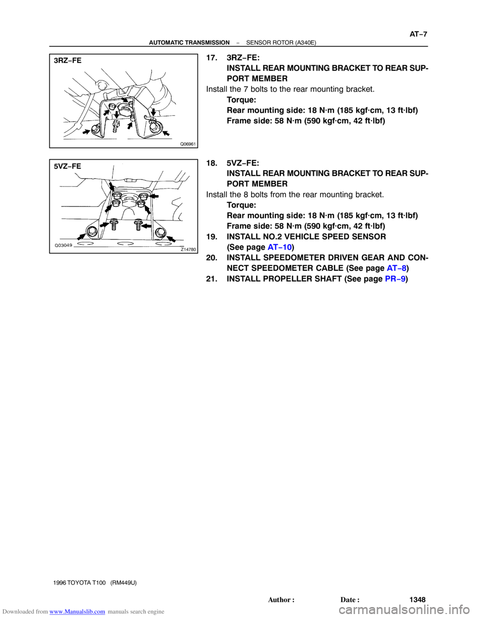
17. 3RZ−FE:
INSTALL REAR MOUNTING BRACKET TO REAR SUP-
PORT MEMBER
Install the 7 bolts to the rear mounting bracket.
Torque:
Rear mounting side: 18 N·m (185 kgf·cm, 13 ft·lbf)
Frame side: 58 N·m (590 kgf·cm, 42 ft·lbf)
18. 5VZ−FE:
INSTALL REAR MOUNTING BRACKET TO REAR SUP-
PORT MEMBER
Install the 8 bolts from the rear mounting bracket.
Torque:
Rear mounting side: 18 N·m (185 kgf·cm, 13 ft·lbf)
Frame side: 58 N·m (590 kgf·cm, 42 ft·lbf)
19. INSTALL NO.2 VEHICLE SPEED SENSOR
(See page AT−10)
20. INSTALL SPEEDOMETER DRIVEN GEAR AND CON-
NECT SPEEDOMETER CABLE (See page AT−8)
21. INSTALL PROPELLER SHAFT (See page PR−9)
Page 1376 of 2062

Downloaded from www.Manualslib.com manuals search engine Q04730
AT01W−02
Q06873
Z15613
A340E
SST
SST
A340F
Q07623
A340ESST
SST A340F
AT−8
− AUTOMATIC TRANSMISSIONSPEEDOMETER DRIVEN GEAR
1349 Author�: Date�:
1996 TOYOTA T100 (RM449U)
SPEEDOMETER DRIVEN GEAR
ON−VEHICLE REPAIR
1. DISCONNECT SPEEDOMETER CABLE AND RE-
MOVE SPEEDOMETER DRIVEN GEAR
(a) Loosen the serrated collar with pliers. Do not lose the felt
dust protector and washer.
(b) Disconnect the speedometer cable.
(c) Remove the bolt and locking plate. Pry out the speedom-
eter driven gear assembly.
(d) Remove the O−ring from the speedometer drive gear as-
sembly.
(e) Remove the clip and speedometer driven gear from the
speedometer driven gear sleeve.
2. REMOVE SPEEDOMETER DRIVEN GEAR OIL SEAL
Using SST, remove the oil seal.
SST 09921−00010
3. INSTALL SPEEDOMETER DRIVEN GEAR OIL SEAL
Using SST, install a new oil seal.
SST 09201−10000 (09201−01080)
Drive in depth: 20 mm (0.79 in.)
4. INSTALL SPEEDOMETER DRIVEN GEAR AND CON-
NECT SPEEDOMETER CABLE
(a) Install the clip and speedometer driven gear to the
speedometer driven gear sleeve.
(b) Install a new O−ring to the speedometer driven gear as-
sembly.
(c) Install the speedometer driven gear.
(d) Install the locking plate with the bolt.
Torque: 16 N·m (160 kgf·cm, 12 ft·lbf)
(e) Connect the speedometer cable.