Page 1349 of 2062

Downloaded from www.Manualslib.com manuals search engine WM0064
MT03U−01
WM0065
Q00930
MT0780
MT−24
− MANUAL TRANSMISSION (W59)OUTPUT SHAFT
1996 TOYOTA T100 (RM449U)
INSPECTION
1. INSPECT 1ST GEAR SYNCHRONIZER RING
(a) Check for wear or damage.
(b) Check the braking effect of the synchronizer ring.
Turn the synchronizer ring in one direction while pushing
it to the gear cone. Check that the ring locks.
If the braking effect is insufficient, apply a small amount of the
fine lapping compound between the synchronizer ring and gear
cone. Lightly rub the synchronizer ring and gear cone together.
NOTICE:
Ensure the fine lapping compound is completely washed
off after rubbing.
(c) Check again the braking effect of the synchronizer ring.
(d) Using a feeler gauge, measure the clearance between
the synchronizer ring back and gear spline end.
Minimum clearance: 0.5 mm (0.020 in.)
If the clearance is less than the minimum, replace the synchro-
nizer ring, and apply a small amount of the fine lapping com-
pound on gear cone.
NOTICE:
Ensure the fine lapping compound is completely washed
off after rubbing.
2. INSPECT 2ND AND 3RD GEAR SYNCHRONIZER
RINGS
(a) Check for wear or damage.
(b) Install the synchronizer inner ring, middle ring and outer
ring to each gear.
(c) Check the braking effect of the synchronizer ring. Turn the
synchronizer ring in one direction while pushing it to the
gear cone. Check that the ring locks.
If it does not lock, replace the synchronizer ring.
Page 1643 of 2062

Downloaded from www.Manualslib.com manuals search engine BR3295
Stop Light Switch
Pedal Height Push RodBR08R−01
BR4980
A BR−6
− BRAKEBRAKE PEDAL
1611 Author�: Date�:
1996 TOYOTA T100 (RM449U)
BRAKE PEDAL
ON−VEHICLE INSPECTION
1. CHECK PEDAL HEIGHT
Pedal height from asphalt sheet:
Extra cab 4WD:
146.7 − 156.7 mm (5.776 − 6.169 in.)
Except extra cab 4WD:
149.7 − 159.7 mm (5.894 − 6.287 in.)
2. IF NECESSARY, ADJUST PEDAL HEIGHT
(a) Disconnect the connector from the stop light switch.
(b) Loosen the stop light switch lock nut and remove the stop
light switch.
(c) Loosen the push rod lock nut.
(d) Adjust the pedal height by turning the pedal push rod.
(e) Tighten the push rod lock nut.
Torque: 25 N·m (260 kgf·cm, 19 ft·lbf)
(f) Install the stop light switch and turn it until it lightly con-
tacts the pedal stopper.
(g) Turn the stop light switch back one turn.
(h) Check the clearance (A) between stop light switch and
pedal.
Clearance: 0.5 − 2.4 mm (0.020 − 0.094 in.)
(i) Tighten the stop light switch lock nut.
(j) Check the stop lights come on when the brake pedal is de-
pressed, and go off when the brake pedal is released.
(k) After adjusting the pedal height, check the pedal freeplay.
HINT:
If clearance (A) between the stop light switch and the pedal
stopper has been adjusted correctly, the pedal freeplay will
meet the specifications.
Page 1654 of 2062
Downloaded from www.Manualslib.com manuals search engine BR2237
BR08Z−01
BR2238
GOOD NO GOOD
1st2nd3rd
− BRAKEBRAKE BOOSTER ASSEMBLY
BR−17
1622 Author�: Date�:
1996 TOYOTA T100 (RM449U)
BRAKE BOOSTER ASSEMBLY
ON−VEHICLE INSPECTION
1. OPERATING CHECK
(a) Depress the brake pedal several times with the engine off,
and check that there is no change in the pedal reserve
distance.
(b) Depress the brake pedal and start engine. If the pedal
goes down slightly, operation is normal.
2. AIR TIGHTNESS CHECK
(a) Start the engine and stop it after 1 or 2 minutes. Depress
the brake pedal several times slowly.
If the pedal goes down furthest the 1st time, but gradually rises
after the 2nd or 3rd time, the booster is air tight.
(b) Depress the brake pedal while the engine is running, and
stop it with the pedal depressed. If there is no change in
pedal reserve travel after holding the pedal for 30 se-
conds, the booster is air tight.
Page 1657 of 2062

Downloaded from www.Manualslib.com manuals search engine BR092−01
BR3286
F03521
SST
Gasket
Z03607
SST BR−20
− BRAKEBRAKE BOOSTER ASSEMBLY
1996 TOYOTA T100 (RM449U)
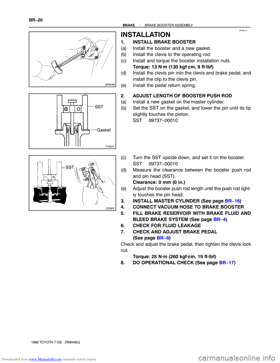
INSTALLATION
1. INSTALL BRAKE BOOSTER
(a) Install the booster and a new gasket.
(b) Install the clevis to the operating rod.
(c) Install and torque the booster installation nuts.
Torque: 13 N·m (130 kgf·cm, 9 ft·lbf)
(d) Install the clevis pin into the clevis and brake pedal, and
install the clip to the clevis pin.
(e) Install the pedal return spring.
2. ADJUST LENGTH OF BOOSTER PUSH ROD
(a) Install a new gasket on the master cylinder.
(b) Set the SST on the gasket, and lower the pin until its tip
slightly touches the piston.
SST 09737−00010
(c) Turn the SST upside down, and set it on the booster.
SST 09737−00010
(d) Measure the clearance between the booster push rod
and pin head (SST).
Clearance: 0 mm (0 in.)
(e) Adjust the booster push rod length until the push rod light-
ly touches the pin head.
3. INSTALL MASTER CYLINDER (See page BR−16)
4. CONNECT VACUUM HOSE TO BRAKE BOOSTER
5. FILL BRAKE RESERVOIR WITH BRAKE FLUID AND
BLEED BRAKE SYSTEM (See page BR−4)
6. CHECK FOR FLUID LEAKAGE
7. CHECK AND ADJUST BRAKE PEDAL
(See page BR−6)
Check and adjust the brake pedal, then tighten the clevis lock
nut.
Torque: 25 N·m (260 kgf·cm, 19 ft·lbf)
8. DO OPERATIONAL CHECK (See page BR−17)
Page 1686 of 2062

Downloaded from www.Manualslib.com manuals search engine BR09Q−01
BR0122
C
A
BAdjusting Bolt
BR0973
Z03640
Z03659
− BRAKEREAR DRUM BRAKE (4WD)
BR−49
1996 TOYOTA T100 (RM449U)
INSTALLATION
Installation is in the reverse order of removal (See page
BR−45).
NOTICE:
Apply lithium soap base glycol grease and high tempera-
ture grease to the parts indicated by the arrows (See page
BR−44).
1. ADJUST BELLCRANK
(a) Lightly pull the bellcrank in direction A until there is no
slack at part B.
(b) In this condition, turn the adjusting bolt so that dimension
C will be 0.4 − 0.8 mm (0.016 − 0.031 in.).
(c) Lock the adjusting bolt with the lock nut.
(d) Connect the parking brake cable to the parking brake bell-
crank and install the clip.
(e) Install the tension spring.
2. CHECK OPERATION OF AUTOMATIC ADJUSTING
MECHANISM
(a) Move the parking brake lever of the front shoe back and
forth. Check that the adjuster turns.
If the adjuster does not turn, check for incorrect installation of
the rear brakes.
(b) Adjust the adjuster length as short as possible.
(c) Install the brake drum.
(d) Pull the parking brake lever all the way up until a clicking
sound can no longer be heard.
3. CHECK CLEARANCE BETWEEN BRAKE SHOES AND
DRUM (See page BR−43)
Shoe clearance: 0.6 mm (0.024 in.)
4. FILL BRAKE RESERVOIR WITH BRAKE FLUID AND
BLEED BRAKE SYSTEM (See Page BR−4)
5. CHECK FOR LEAKS
Page 1694 of 2062

Downloaded from www.Manualslib.com manuals search engine BR09X−01
Z11332
SST
Z11333
A
BR0218
BR0061
SST
− BRAKELOAD SENSING PROPORTIONING AND BY−PASS
VALVE (LSP & BV)BR−57
1996 TOYOTA T100 (RM449U)
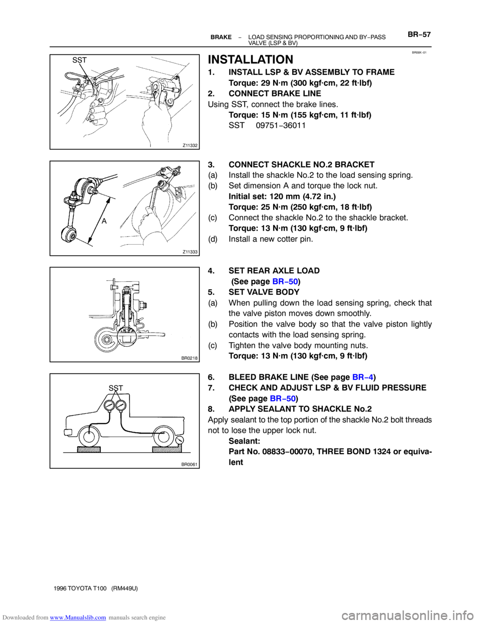
INSTALLATION
1. INSTALL LSP & BV ASSEMBLY TO FRAME
Torque: 29 N·m (300 kgf·cm, 22 ft·lbf)
2. CONNECT BRAKE LINE
Using SST, connect the brake lines.
Torque: 15 N·m (155 kgf·cm, 11 ft·lbf)
SST 09751−36011
3. CONNECT SHACKLE NO.2 BRACKET
(a) Install the shackle No.2 to the load sensing spring.
(b) Set dimension A and torque the lock nut.
Initial set: 120 mm (4.72 in.)
Torque: 25 N·m (250 kgf·cm, 18 ft·lbf)
(c) Connect the shackle No.2 to the shackle bracket.
Torque: 13 N·m (130 kgf·cm, 9 ft·lbf)
(d) Install a new cotter pin.
4. SET REAR AXLE LOAD
(See page BR−50)
5. SET VALVE BODY
(a) When pulling down the load sensing spring, check that
the valve piston moves down smoothly.
(b) Position the valve body so that the valve piston lightly
contacts with the load sensing spring.
(c) Tighten the valve body mounting nuts.
Torque: 13 N·m (130 kgf·cm, 9 ft·lbf)
6. BLEED BRAKE LINE (See page BR−4)
7. CHECK AND ADJUST LSP & BV FLUID PRESSURE
(See page BR−50)
8. APPLY SEALANT TO SHACKLE No.2
Apply sealant to the top portion of the shackle No.2 bolt threads
not to lose the upper lock nut.
Sealant:
Part No. 08833−00070, THREE BOND 1324 or equiva-
lent
Page 1716 of 2062

Downloaded from www.Manualslib.com manuals search engine R07653
SR0097
SR075−01
R09732
− STEERINGSTEERING WHEEL
SR−9
1683 Author�: Date�:
1996 TOYOTA T100 (RM449U)
STEERING WHEEL
INSPECTION
1. CHECK THAT STEERING WHEEL FREEPLAY IS COR-
RECT
With the vehicle stopped and tires pointed straight ahead, rock
the steering wheel gently back and forth with light finger pres-
sure.
Freeplay should not exceed the maximum.
Maimum freeplay: 30 mm (1.18 in.)
4WD:
If the freeplay exceeds the maximum, adjust it in the following
procedure.
2. 4WD:
ADJUST STEERING GEAR
(a) Point the front wheels straight ahead.
(b) Loosen the adjusting screw lock nut.
(c) Turn the sector shaft adjusting screw clockwise to de-
crease steering wheel freeplay and counterclockwise to
increase it.
HINT:
Turn the adjusting screw in small increments and check the
freeplay between each adjustment.
(d) Turn the steering wheel half way around in both direc-
tions.
Check the the freeplay is correct and steering is smooth
and without rough spots.
(e) Torque the adjusting screw lock nut (See page SR−80).
3. CHECK STEERING EFFORT
(a) Center the steering wheel.
(b) Remove the steering wheel pad (See page SR−13).
(c) Start the engine and run it at idle.
(d) Measure the steering effort in both directions.
Reference: 8.3 N·m (85 kgf·cm, 73 in.·lbf)
HINT:
Be sure to consider the tire type, pressure and contact surface
before making your diagnosis.
(e) Torque the steering wheel set nut.
Torque: 35 N·m (360 kgf·cm, 26 ft·lbf)
(f) Install the steering wheel pad (See page SR−20).
Page 1728 of 2062

Downloaded from www.Manualslib.com manuals search engine R07644Red Mark
R07660
Torx ScrewScrew Case
− STEERINGNON−TILT STEERING COLUMN
SR−21
1996 TOYOTA T100 (RM449U)
9. INSTALL COMBINATION SWITCH WITH SPIRAL
CABLE
(a) Install the 4 screws.
(b) Connect the airbag connector.
(c) Connect the connectors.
(d) Install the 2 screws.
10. INSTALL DUCT HEATER TO REGISTER NO.2
Install the screw.
11. INSTALL LOWER FINISH PANEL NO.1
(a) Install the lock nuts and light control rheostat.
(b) Tighten the 4 panel set bolts.
(c) Install the cowl side trim and clip.
(d) Install the front door scuff plate with the 4 screws.
(e) Install the engine hood release lever with the 2 screws.
12. A/T:
INSTALL UPPER AND LOWER COLUMN COVERS
Install the 6 screws.
13. M/T:
INSTALL UPPER AND LOWER COLUMN COVERS
Install the 7 screws.
14. CENTER SPIRAL CABLE
(a) Check that the front wheels are facing straight ahead.
(b) Turn the spiral counterclockwise by hand until it becomes
harder to turn the cable.
(c) Then turn the spiral cable clockwise about 3 turns to align
the red mark.
HINT:
The spiral cable turns clockwise about 3 turns to either left or
right of the center.
15. INSTALL STEERING WHEEL
(a) Align the matchmarks on the wheel and main shaft.
(b) Torque the set nut.
Torque: 35 N·m (360 kgf·cm, 26 ft·lbf)
(c) Connect the connector.
16. INSTALL STEERING WHEEL PAD
NOTICE:
�Make sure the wheel pad is installed to the specified
torque.
�If the wheel pad has been dropped, or there are
cracks, dents in the case or connector, replace the
wheel pad with a new one.
�When installing the wheel pad, take care that the wir-
ings do not interfere with other parts and are not
pinched between other parts.