Page 15 of 1354
D02186
AX127−01
Q08747
Q08761
D02187
Q08763
− AUTOMATIC TRANSAXLE (A241E)AUTOMATIC TRANSAXLE UNIT
AX−15
1996 RAV4 (RM447U)
REMOVAL
1. DISCONNECT THROTTLE CABLE
2. REMOVE ENGINE COOLANT RESERVOIR TANK
3. REMOVE AIR CLEANER ASSEMBLY
(a) Disconnect the connector and ABS relay.
(b) Remove the 3 bolts and air cleaner assembly.
4. REMOVE GROUND CABLE
Remove the bolt from the transaxle.
Torque: 19 N·m (194 kgf·cm, 14 ft·lbf)
5. REMOVE SET NUT OF ENGINE WIRE CLAMP
6. REMOVE STARTER
(a) Disconnect the connector and nut from the starter.
(b) Remove the 2 bolts and disconnect the engine wire.
Torque: 39 N·m (400 kgf·cm, 29 ft·lbf)
(c) Remove the starter.
7. REMOVE 3 UPPER SIDE TRANSAXLE MOUNTING
BOLTS
Torque: 64 N·m (650 kgf·cm, 47 ft·lbf)
8. INSTALL ENGINE SUPPORT FIXTURE
Page 18 of 1354
Z18887
A
A
A
B
Q08772
Q08773
A
B AX−18
− AUTOMATIC TRANSAXLE (A241E)AUTOMATIC TRANSAXLE UNIT
1996 RAV4 (RM447U)
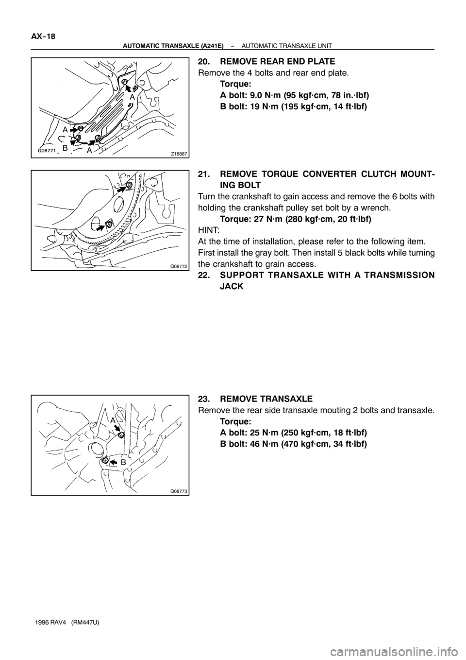
20. REMOVE REAR END PLATE
Remove the 4 bolts and rear end plate.
Torque:
A bolt: 9.0 N·m (95 kgf·cm, 78 in.·lbf)
B bolt: 19 N·m (195 kgf·cm, 14 ft·lbf)
21. REMOVE TORQUE CONVERTER CLUTCH MOUNT-
ING BOLT
Turn the crankshaft to gain access and remove the 6 bolts with
holding the crankshaft pulley set bolt by a wrench.
Torque: 27 N·m (280 kgf·cm, 20 ft·lbf)
HINT:
At the time of installation, please refer to the following item.
First install the gray bolt. Then install 5 black bolts while turning
the crankshaft to grain access.
22. SUPPORT TRANSAXLE WITH A TRANSMISSION
JACK
23. REMOVE TRANSAXLE
Remove the rear side transaxle mouting 2 bolts and transaxle.
Torque:
A bolt: 25 N·m (250 kgf·cm, 18 ft·lbf)
B bolt: 46 N·m (470 kgf·cm, 34 ft·lbf)
Page 20 of 1354

AT0953
SST
AX05A−02
AT3306
Hold
Lock
Free
Turn
D00776
AT4184
AX−20
− AUTOMATIC TRANSAXLE (A241E)TORQUE CONVERTER CLUTCH AND DRIVE PLATE
1996 RAV4 (RM447U)
TORQUE CONVERTER CLUTCH
AND DRIVE PLATE
INSPECTION
1. INSPECT ONE−WAY CLUTCH
(a) Install SST into the inner race of the one−way clutch.
SST 09350−32014 (09351−32010)
(b) Install SST so that it fits in the notch of the converter clutch
hub and outer race of the one−way clutch.
SST 09350−32014 (09351−32020)
(c) With the torque converter clutch standing on its side,the
clutch locks when turned counterclockwise, and rotates
freely and smoothly clockwise.
If necessary, clean the converter clutch and retest the clutch.
Replace the converter clutch if the clutch still fails the test.
2. MEASURE DRIVE PLATE RUNOUT AND INSPECT
RING GEAR
Set up a dial indicator, measure the drive plate runout.
Maximum runout: 0.20 mm (0.0079 in.)
If the runout is not within the specification or if the ring gear is
damaged, replace the drive plate. If installing a new drive plate,
note the orientation of spacers and tighten the bolts.
Torque: 83 N·m (850 kgf·cm, 61 ft·lbf)
3. MEASURE TORQUE CONVERTER CLUTCH SLEEVE
RUNOUT
Temporarily mount the torque converter clutch to the drive
plate. Set up a dial indicator, measure the torque converter
clutch sleeve runout.
Maximum runout: 0.30 mm (0.0118 in.)
If the runout is not within the specification, try to correcting by
reorienting the installation of the converter clutch.
Page 43 of 1354

AT0952
SST
AX04W−01
AT0953
SST
AT3306
Hold
Lock
Free
Turn
AT2821
AX−22
− AUTOMATIC TRANSAXLE (A540H)TORQUE CONVERTER CLUTCH AND DRIVE PLATE
1996 RAV4 (RM447U)
TORQUE CONVERTER CLUTCH
AND DRIVE PLATE
INSPECTION
1. INSPECT ONE−WAY CLUTCH
(a) Install SST into the inner race of the one−way clutch.
SST 09350−32014 (09351−32010)
(b) Install SST so that it fits in the notch of the converter clutch
hub and outer race of the one−way clutch.
SST 09350−32014 (09351−32020)
(c) With the torque converter clutch standing on its side, the
clutch locks when turned counterclockwise, and rotates
freely and smoothly clockwise.
If necessary, clean the converter clutch and retest the clutch.
Replace the converter clutch if the clutch still fails the test.
2. MEASURE DRIVE PLATE RUNOUT AND INSPECT
RING GEAR
(a) Set up a dial indicator and measure the drive plate runout.
(b) Check the damage of the ring gear.
Maximum runout: 0.20 mm (0.0079 in.)
If the runout is not within the specification, or ring gear is dam-
aged replace the drive plate.
Torque: 83 N·m (850 kgf·cm, 61 ft·lbf)
Page 44 of 1354
AT4184
− AUTOMATIC TRANSAXLE (A540H)TORQUE CONVERTER CLUTCH AND DRIVE PLATE
AX−23
1996 RAV4 (RM447U)
3. MEASURE TORQUE CLUTCH CONVERTER SLEEVE
RUNOUT
(a) Temporarily mount the torque converter clutch to the drive
plate. Set up a dial indicator and measure the torque con-
verter clutch sleeve runout.
Maximum runout: 0.30 mm (0.0118 in.)
If the runout is not within the specification, try to correct by reori-
enting the installation of the converter clutch.
HINT:
Mark the position of the converter clutch to ensure correct
installation.
(b) Remove the torque converter clutch.
Page 46 of 1354

N11771
1
82 3
4
65 7
BE0J4−04
Z10028
1
2
OFF
ON
N01923
N01924
N01925
− BODY ELECTRICALIGNITION SWITCH AND KEY UNLOCK WARNING
SWITCHBE−11
1996 RAV4 (RM447U)
INSPECTION
1. INSPECT IGNITION SWITCH CONTINUITY
Switch positionTester connectionSpecified condition
LOCK−No continuity
ACC2 − 3Continuity
ON2 − 3 − 4, 6 − 7Continuity
START1−2−4, 6−7−8Continuity
If continuity is not as specified, replace the switch.
2. INSPECT KEY UNLOCK WARNING SWITCH CONTI-
NUITY
Switch positionTester connectionSpecified condition
SW OFF
(Key removed) −No continuity
SW ON (Key set)1 − 2Continuity
If continuity is not as specified, replace the switch.
3. Key Unlock Warning System:
INSPECT INTEGRATION RELAY OPERATION
(a) Connect the positive (+) lead from the battery to terminal
A1.
(b) Connect the negative (−) lead from the battery to termi-
nals A5, A6 and A10.
(c) Check the buzzer sounds.
(d) Disconnect the negative (−) lead from the battery to termi-
nals A6.
(e) Check that the buzzer stops sounding.
(f) Connect the negative (−) lead from the battery to termi-
nals A6.
(g) Disconnect the negative (−) lead from the battery to termi-
nals A5.
(h) Check that the buzzer stops sounding.
If operation is not as specified, replace the relay.
Page 52 of 1354

N18226
Beam Angle Gauge
(Vertical Direction)
Beam is
UpwardBeam is
Downward
FrontOK
Bubble OKOK
Z17544
Beam Angle Gauge
(Horizontal Direction)
FrontAcceptable Range”O” Reading
Adjusting
Screw B Holder Assembly
N18085
”O” Reading Holer Assembly
Adjusting Screw B
N18086
”O” Reading
PawlTemporary Pawl
− BODY ELECTRICALHEADLIGHT AND TAILLIGHT SYSTEM
BE−17
1996 RAV4 (RM447U)
2. ADJUST HEADLIGHT AIM
(a) Replace the headlight.
(b) Do the following before inspection.
�Make sure that the body around the headlight is not
deformed.
�Park the vehicle on a level spot.
�The driver gets into the driver’s seat and puts the
vehicle in a state ready for driving (with a full tank).
�Bounce the vehicle several times.
(c) Adjust the headlight aim in vertical direction.
(1) Using adjusting screw A, adjustment the headlight
aim to within the specifications.
(2) Make sure that the gauge bubble is within the ac-
ceptable range.
HINT:
If the gauge bubble is outside the acceptable range, check that
the vehicle is parked on a level spot.
Readjust the headlight aim after parking the vehicle on a level
spot.
(d) Adjust the headlight aim in horizontal direction.
Using adjusting screw B, adjust the headlight aim to within
the specifications.
3. HOW TO RESET LH AND RH AIMING INDICATORS
(Unlocking method)
HINT:
These operations should be done only when the head adjust-
ment of the headlight aim is necessary, for example in case the
headlight aim ”0” mark deviates from the acceptable range
when the headlight is reassembled after repair.
(a) Turn the adjusting screw B to the right, and remove the
holder assembly from the cylindrical part of the housing.
(b) Unlock the holder assembly.
Page 53 of 1354
N18087
”O” Reading Temporary
Pawl
Temporary PawlView A View A
Z17544
Beam Angle Gauge
(Horizontal Direction)
FrontAcceptable Range”O” Reading
Adjusting
Screw B Holder Assembly BE−18
− BODY ELECTRICALHEADLIGHT AND TAILLIGHT SYSTEM
1996 RAV4 (RM447U)
(c) Insert the holder assembly, unlock in step (b), to the screw
and housing again.
HINT:
When the assembly is inserted till the pawl for temporary set is
hooded to the cross slit of the housing as shown in view A, set-
ting is completed.
(d) Turn the adjusting screw B to the left and adjust the LH
and RH headlight aims.
(e) Pull the holder assembly backwards and lock it.