Page 92 of 1354
V04922
12
Tape player SOUND QUALITY POOR (VOLUME FAINT)
Functions OK if different cassette tape inserted?Ye s
Cassette tape faulty.
No
Operates normally after cleaning the heads?
NoYe s
Head dirty.
Is radio operating normally?
NoYe s
Radio assembly faulty.
Is speaker properly installed?
Ye sNo
Install properly.
Speaker faulty. Temporarily install another speaker. Functions OK?
No
Radio assembly faulty.
13Tape PlayerTAPE JAMMED, MALFUNCTION WITH TAPE SPEED OR
AUTO−REVERSE
Functions OK if different tape (less than 120 mins.) is inserted?Ye s
Ye s
Cassette tape faulty.
No
Is there a foreign object inside tape player?
NoYe s
Remove foreign object.
Operates normally after cleaning the heads?Ye s
Head dirty.
No
Radio assembly faulty.
BE−76
− BODY ELECTRICALAUDIO SYSTEM
1996 RAV4 (RM447U)
Page 93 of 1354
V07436
14
Tape PlayerAPS, SKIP, RPT BUTTONS NOT OPERATING
Functions OK if different cassette tape inserted?Radio assembly faulty. No
Ye s
Cassette tape faulty. {Less than 3 secs. of silence between songs (APS, RPT).
Less than 15 secs. of silence (SKIP).}
15
Tape Player
CASSETTE TAPE WILL NOT BE EJECTED
Is tape player operating normally?No
Cassette tape jammed.
Is radio operating normally?Ye s
NoYe s
Radio assembly faulty.
Check if DOME fuse is OK?
OKNG
Replace fuse.
Is B+ applied to radio assembly?
Ye s
Radio assembly faulty.No
B+ wire haness faulty.
− BODY ELECTRICALAUDIO SYSTEM
BE−77
1996 RAV4 (RM447U)
Page 105 of 1354
H01976
Centering Bolt
Standard Bolt
BO0ZS−01
N11408
N11409
N11458
BO−8
− BODYHOOD
1996 RAV4 (RM447U)
HOOD
ADJUSTMENT
HINT:
Since the centering bolt is used as the hood hinge and lock set
bolt, the hood and lock cannot be adjusted with it on. Substitute
the bolt with washer for the centering bolt.
1. ADJUST HOOD IN FORWARD/REARWARD AND
LEFT/RIGHT DIRECTIONS
Adjust the hood by loosening the hood side hinge bolts.
Torque: 13 N·m (130 kgf·cm, 9 ft·lbf)
2. ADJUST FRONT EDGE OF HOOD IN VERTICAL
DIRECTIONS
Adjust the hood by turning the cushions.
3. ADJUST HOOD LOCK
Adjust the lock by loosening the 2 bolts and nut.
Torque:
7.5 N·m (75 kgf·cm, 65 in.·lbf) for bolt
8.5 N·m (85 kgf·cm, 74 in.·lbf) for nut
Page 171 of 1354

BR02M−02
R09358
R09359
R12236
A BR−12
− BRAKEBRAKE MASTER CYLINDER
1996 RAV4 (RM447U)
DISASSEMBLY
1. REMOVE RESERVOIR
(a) Remove the set screw and pull out the reservoir.
Torque:
1.8 N·m (18 kgf·cm, 16 in.·lbf)
(b) Remove the cap and strainer from the reservoir.
2. REMOVE 2 GROMMETS
3. PLACE CYLINDER IN VISE
4. REMOVE PISTON STOPPER BOLT
Using a screwdriver, push the pistons in all the way and remove
the piston stopper bolt and gasket.
HINT:
Tape the screwdriver tip before use.
Torque:
10 N·m (100 kgf·cm, 7 ft·lbf)
5. REMOVE 2 PISTONS AND SPRINGS
(a) Push in the piston with a screwdriver and remove the
snap ring with snap ring pliers.
HINT:
Tape the screwdriver tip before use.
(b) Remove the No.1 piston and spring by hand, pulling
straight out, not at an angle.
NOTICE:
�If pulled out and installed at an angle, there is a possi-
bility that the cylinder bore could be damaged.
�At the time of reassembly, be careful not to damage
the rubber lips on the pistons.
(c) Place a rag and 2 wooden blocks on the work table and
lightly tap the cylinder flange against the block edges until
the piston drops out of the cylinder.
HINT:
Make sure the distance (A) from the rag to the top of the blocks
is at least 100 mm (3.94 in.).
Page 178 of 1354

BR0M3−01
F03521
SST
Gasket
N00744
SST
− BRAKEBRAKE BOOSTER ASSEMBLY
BR−19
1996 RAV4 (RM447U)
INSTALLATION
1. INSTALL BRAKE BOOSTER
(a) Install the booster and a new gasket.
(b) Install the clevis to the operating rod.
(c) Install and torque the booster installation nuts.
Torque:
13 N·m (130 kgf·cm, 9 ft·lbf)
(d) Insert the clevis pin into clevis, brake pedal, and install the
clip to the clevis pin.
(e) Install the pedal return spring.
2. ADJUST LENGTH OF BOOSTER PUSH ROD
(a) Install a new gasket on the master cylinder.
(b) Set the SST on the gasket, and lower the pin until its tip
slightly touches the piston.
SST 09737−00010
(c) Turn the SST upside down, and set it on the booster.
SST 09737−00010
(d) Measure the clearance between the booster push rod
and pin head (SST).
Clearance: 0 mm (0 in.)
(e) Adjust the booster push rod length until the push rod
slightly touches the pin head.
3. INSTALL CHARCOAL CANISTER TO ORIGINAL POSI-
TION
4. INSTALL MASTER CYLINDER
5. CONNECT VACUUM HOSE TO BRAKE BOOSTER
6. FILL BRAKE RESERVOIR WITH BRAKE FLUID AND
BLEED BRAKE SYSTEM (See page BR−4)
7. M/T:
BLEED CLUTCH SYSTEM
8. CHECK FOR LEAKS
9. CHECK AND ADJUST BRAKE PEDAL
(See page BR−6)
Check and adjust the brake pedal, then tighten the clevis lock
nut.
Torque:
25 N·m (260 kgf·cm, 19 ft·lbf)
10. DO OPERATIONAL CHECK (See page BR−16)
Page 184 of 1354

BR0M6−01
R10631
R10633
R10634
− BRAKEFRONT BRAKE CALIPER
BR−25
1996 RAV4 (RM447U)
DISASSEMBLY
1. REMOVE CYLINDER BOOT SET RING AND
CYLINDER BOOT
Using a screwdriver, remove the cylinder boot set ring and cylin-
der boot.
2. REMOVE PISTON
(a) Put a piece of cloth or equivalent between the piston and
the caliper.
(b) Use compressed air to remove the piston from the cylin-
der.
CAUTION:
Do not place your fingers in front of the piston when using
compressed air.
3. REMOVE PISTON SEAL
Using a screwdriver, remove the piston seal.
4. REMOVE SLIDING PINS AND DUST BOOTS
(a) Remove the 2 sliding pins from the torque plate.
NOTICE:
At the time of reassembly, please refer to the following
item.
Insert the sliding pin with the sliding bushing into the upper
side.
(b) Using a screwdriver and a hammer, tap out the 2 dust
boots.
HINT:
At the time of reassembly, please refer to the following item.
Use a 21 mm socket and tap in 2 new dust boots into the torque
plate.
NOTICE:
At the time of reassembly, please refer to the following
item.
Confirm that the metal plate portion of the dust boot fits
snugly in the torque plate.
Page 191 of 1354

BR0M8−01
BR1542
BR0046
BR1543
BR−32
− BRAKEREAR DRUM BRAKE
1996 RAV4 (RM447U)
INSPECTION
1. INSPECT DISASSEMBLED PARTS
Inspect the disassembled parts for wear, rust or damage.
2. MEASURE BRAKE SHOE LINING THICKNESS
Using a ruler, measure the shoe lining thickness.
Standard thickness: 5.0 mm (0.197 in.)
Minimum thickness: 1.0 mm (0.039 in.)
If the shoe lining is less than the minimum or shows signs of un-
even wear, replace the brake shoes.
HINT:
If a brake shoe needs replacing, the brake shoes must be re-
placed as a set.
3. MEASURE BRAKE DRUM INSIDE DIAMETER
Using a vernier calipers, measure the inside diameter of the
drum.
Standard inside diameter: 228.6 mm (9.000 in.)
Maximum inside diameter: 230.6 mm (9.079 in.)
If the drum is scored or worn, the brake drum may be lathed to
the maximum inside diameter.
4. INSPECT REAR BRAKE LINING AND DRUM FOR
PROPER CONTACT
If the contact between the brake lining and drum is improper, re-
pair the lining with a brake shoe grinder, or replace the brake
shoe assembly.
Page 214 of 1354
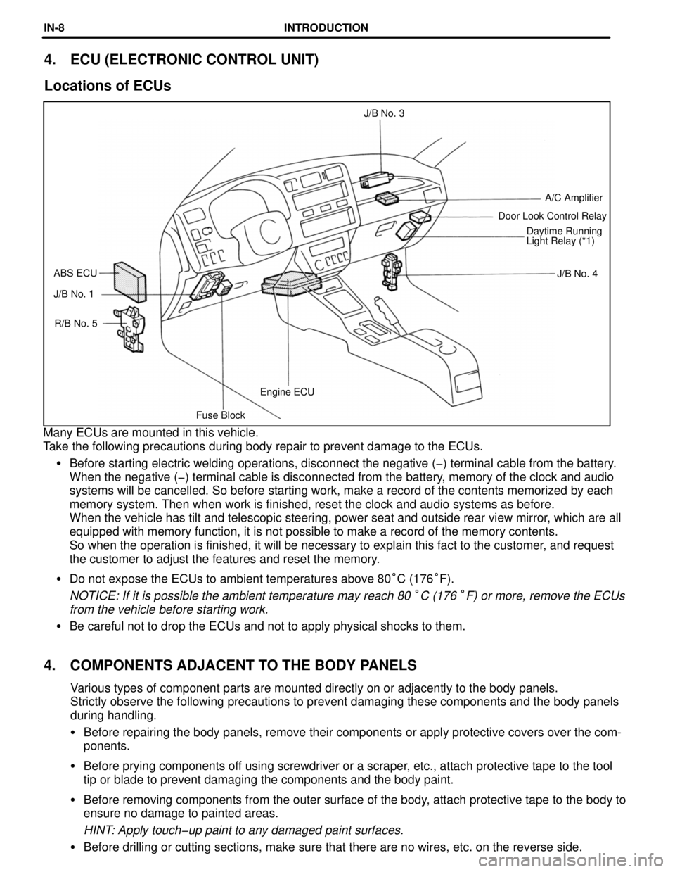
Fuse BlockEngine ECU R/B No. 5 J/B No. 1J/B No. 4 ABS ECUDaytime Running
Light Relay (*1) Door Look Control RelayA/C Amplifier J/B No. 3
4. ECU (ELECTRONIC CONTROL UNIT)
Locations of ECUs
Many ECUs are mounted in this vehicle.
Take the following precautions during body repair to prevent damage to the ECUs.
�Before starting electric welding operations, disconnect the negative (-) terminal cable from the battery.
When the negative (-) terminal cable is disconnected from the battery, memory of the clock and audio
systems will be cancelled. So before starting work, make a record of the contents memorized by each
memory system. Then when work is finished, reset the clock and audio systems as before.
When the vehicle has tilt and telescopic steering, power seat and outside rear view mirror, which are all
equipped with memory function, it is not possible to make a record of the memory contents.
So when the operation is finished, it will be necessary to explain this fact to the customer, and request
the customer to adjust the features and reset the memory.
�Do not expose the ECUs to ambient temperatures above 80°C (176°F).
NOTICE: If it is possible the ambient temperature may reach 80 °C (176 °F) or more, remove the ECUs
from the vehicle before starting work.
�Be careful not to drop the ECUs and not to apply physical shocks to them.
4. COMPONENTS ADJACENT TO THE BODY PANELS
Various types of component parts are mounted directly on or adjacently to the body panels.
Strictly observe the following precautions to prevent damaging these components and the body panels
during handling.
�Before repairing the body panels, remove their components or apply protective covers over the comœ
ponents.
�Before prying components off using screwdriver or a scraper, etc., attach protective tape to the tool
tip or blade to prevent damaging the components and the body paint.
�Before removing components from the outer surface of the body, attach protective tape to the body to
ensure no damage to painted areas.
HINT: Apply touch-up paint to any damaged paint surfaces.
�Before drilling or cutting sections, make sure that there are no wires, etc. on the reverse side.
INTRODUCTIONINœ8