Page 50 of 1354

BE1MW−01
Z17623
HEAD
TA I L
OFFRight
LeftFlash
8
7
17 16
1413
Z13558
3
4
21
3
4 2
1
Z05657
3 21 3
21
55
− BODY ELECTRICALHEADLIGHT AND TAILLIGHT SYSTEM
BE−15
1996 RAV4 (RM447U)
INSPECTION
1. INSPECT LIGHT CONTROL SWITCH CONTINUITY
Switch positionTester connectionSpecified condition
OFF−No continuity
TAIL14 − 16Continuity
HEAD13 − 14 − 16Continuity
If continuity is not as specified, replace the switch.
2. INSPECT HEADLIGHT DIMMER SWITCH CONTINU-
ITY
Switch positionTester connectionSpecified condition
Flash7 − 8 − 16Continuity
Low beam16 − 17Continuity
High beam7 − 16Continuity
If continuity is not as specified, replace the switch.
3. INSPECT HEADLIGHT CONTROL RELAY CONTINU-
ITY
ConditionTester connectionSpecified condition
Constant3 − 4Continuity
Apply B+ between
terminals 3 and 4.1 − 2Continuity
If continuity is not as specified, replace the relay.
4. INSPECT TAILLIGHT CONTROL RELAY CONTINUITY
ConditionTester connectionSpecified condition
Constant1 − 2Continuity
Apply B+ between
terminals 1 and 2.3 − 5Continuity
If continuity is not as specified, replace the relay.
5. Light−on Warning System:
INSPECT INTEGRATION RELAY OPERATION
(a) Connect the positive (+) lead from the battery to terminal
1 and 12, the negative (−) lead to terminals 10.
(b) Check that the buzzer sounds when the negative (−) lead
from the battery is connected to terminal 6.
If operation is not as specified, replace the relay.
6. INSPECT DOOR COURTESY SWITCH CONTINU-
ITY(See pageBE−22)
Page 51 of 1354
BE1MX−01
N18226
Beam Angle Gauge
(Vertical Direction)
Beam is
UpwardBeam is
Downward
FrontOK
Bubble OKOK
Z17543
FrontAcceptable Range”O” Reading
Adjusting
Screw B Beam Angle Gauge
(Horizontal Direction) BE−16
− BODY ELECTRICALHEADLIGHT AND TAILLIGHT SYSTEM
1996 RAV4 (RM447U)
ADJUSTMENT
1. ADJUST HEADLIGHT AIM
(a) Do the following before inspection.
�Make sure that the body around the headlight is not
deformed.
�Park the vehicle on a level spot.
�The driver gets into the driver’s seat and puts the
vehicle in a state ready for driving (with a full tank).
�Bounce the vehicle several times.
(b) Adjust the headlight aim in vertical direction.
If the bubble is outside the acceptable range of the beam angle
gauge, adjust it by using adjusting screw A.
(c) Adjust the headlight aim in horizontal direction.
If ”0” mark is not within the acceptable range, adjust the ”0”
reading to the ”0” mark using adjusting screw B.
Page 52 of 1354

N18226
Beam Angle Gauge
(Vertical Direction)
Beam is
UpwardBeam is
Downward
FrontOK
Bubble OKOK
Z17544
Beam Angle Gauge
(Horizontal Direction)
FrontAcceptable Range”O” Reading
Adjusting
Screw B Holder Assembly
N18085
”O” Reading Holer Assembly
Adjusting Screw B
N18086
”O” Reading
PawlTemporary Pawl
− BODY ELECTRICALHEADLIGHT AND TAILLIGHT SYSTEM
BE−17
1996 RAV4 (RM447U)
2. ADJUST HEADLIGHT AIM
(a) Replace the headlight.
(b) Do the following before inspection.
�Make sure that the body around the headlight is not
deformed.
�Park the vehicle on a level spot.
�The driver gets into the driver’s seat and puts the
vehicle in a state ready for driving (with a full tank).
�Bounce the vehicle several times.
(c) Adjust the headlight aim in vertical direction.
(1) Using adjusting screw A, adjustment the headlight
aim to within the specifications.
(2) Make sure that the gauge bubble is within the ac-
ceptable range.
HINT:
If the gauge bubble is outside the acceptable range, check that
the vehicle is parked on a level spot.
Readjust the headlight aim after parking the vehicle on a level
spot.
(d) Adjust the headlight aim in horizontal direction.
Using adjusting screw B, adjust the headlight aim to within
the specifications.
3. HOW TO RESET LH AND RH AIMING INDICATORS
(Unlocking method)
HINT:
These operations should be done only when the head adjust-
ment of the headlight aim is necessary, for example in case the
headlight aim ”0” mark deviates from the acceptable range
when the headlight is reassembled after repair.
(a) Turn the adjusting screw B to the right, and remove the
holder assembly from the cylindrical part of the housing.
(b) Unlock the holder assembly.
Page 53 of 1354
N18087
”O” Reading Temporary
Pawl
Temporary PawlView A View A
Z17544
Beam Angle Gauge
(Horizontal Direction)
FrontAcceptable Range”O” Reading
Adjusting
Screw B Holder Assembly BE−18
− BODY ELECTRICALHEADLIGHT AND TAILLIGHT SYSTEM
1996 RAV4 (RM447U)
(c) Insert the holder assembly, unlock in step (b), to the screw
and housing again.
HINT:
When the assembly is inserted till the pawl for temporary set is
hooded to the cross slit of the housing as shown in view A, set-
ting is completed.
(d) Turn the adjusting screw B to the left and adjust the LH
and RH headlight aims.
(e) Pull the holder assembly backwards and lock it.
Page 220 of 1354
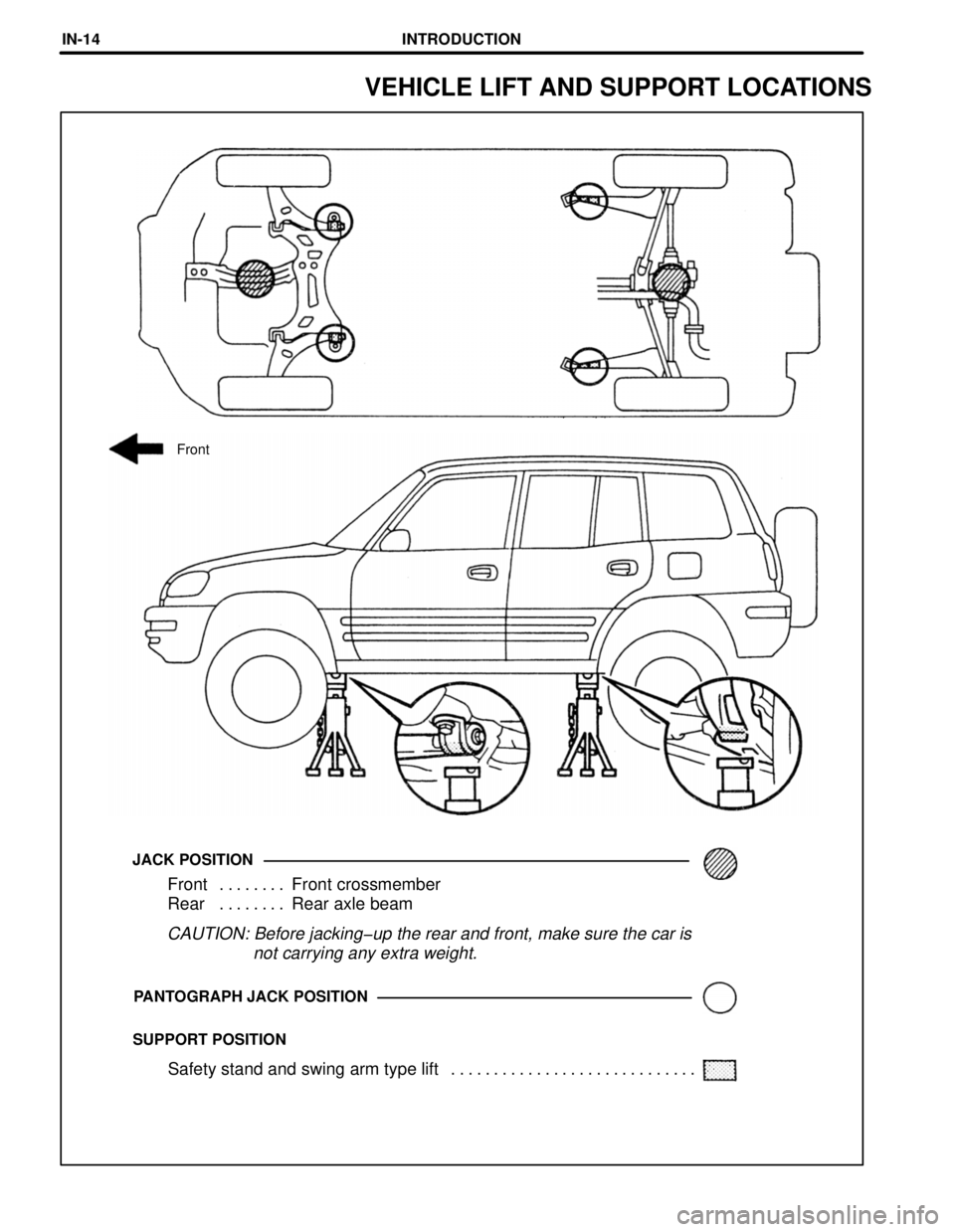
SUPPORT POSITIONPANTOGRAPH JACK POSITION
CAUTION: Before jacking-up the rear and front, make sure the car is
not carrying any extra weight.
Front Front crossmember. . . . . . . .
Rear Rear axle beam. . . . . . . .
JACK POSITION
Front
VEHICLE LIFT AND SUPPORT LOCATIONS
Safety stand and swing arm type lift . . . . . . . . . . . . . . . . . . . . . . . . . . . . .
INTRODUCTIONINœ14
Page 243 of 1354
mmin.
10
0.39
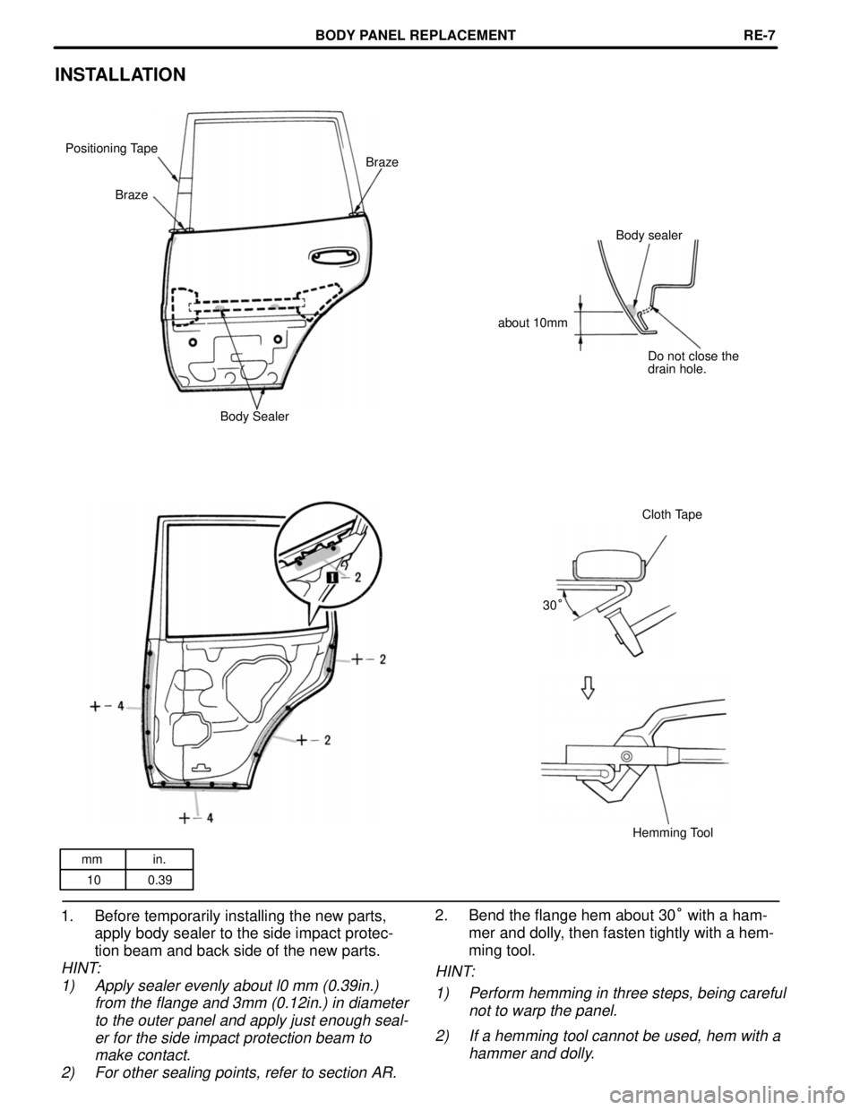
INSTALLATION
Positioning Tape
Body sealer
Braze
Braze
about 10mm
Do not close the
drain hole.
Body Sealer
Cloth Tape
30°
Hemming Tool
1. Before temporarily installing the new parts,
apply body sealer to the side impact protecœ
tion beam and back side of the new parts.
HINT:
1) Apply sealer evenly about 10 mm (0.39in.)
from the flange and 3mm (0.12in.) in diameter
to the outer panel and apply just enough sealœ
er for the side impact protection beam to
make contact.
2) For other sealing points, refer to section AR.
2. Bend the flange hem about 30° with a hamœ
mer and dolly, then fasten tightly with a hemœ
ming tool.
HINT:
1) Perform hemming in three steps, being careful
not to warp the panel.
2) If a hemming tool cannot be used, hem with a
hammer and dolly.
BODY PANEL REPLACEMENTREœ5
Page 245 of 1354
mm in.
10 0.39
INSTALLATION
Positioning Tape
Braze
Braze
Body sealer
about 10mm
Do not close the
drain hole.
Body Sealer
Cloth Tape
30°
Hemming Tool
1. Before temporarily installing the new parts,
apply body sealer to the side impact protecœ
tion beam and back side of the new parts.
HINT:
1) Apply sealer evenly about l0 mm (0.39in.)
from the flange and 3mm (0.12in.) in diameter
to the outer panel and apply just enough sealœ
er for the side impact protection beam to
make contact.
2) For other sealing points, refer to section AR.
2. Bend the flange hem about 30° with a hamœ
mer and dolly, then fasten tightly with a hemœ
ming tool.
HINT:
1) Perform hemming in three steps, being careful
not to warp the panel.
2) If a hemming tool cannot be used, hem with a
hammer and dolly.
BODY PANEL REPLACEMENTREœ7
Page 845 of 1354
76
HEADLIGHT
2
22
IDR-Y
R-W
R-B
R-L R- Y
R-G W-B
R-Y
R-G 1W
H-LP
RELAY15A
H-LP
LH15A
H-LP
RH
HIGH BEAM INDICATOR
LIGHT [COMB. METER] C10
C O M B IN ATIO N
SW
BATTERY 30A
MAIN
NO. 14 2
IG 2
2
W-B
R
9
10 11
R-W
R 63 529
E 1
R-G R-GR- Y R-W
1J 7
1G 9E 1
213
213
HEADLIGHT
LH H 1
HEADLIGHT
RH H 2
80A MAIN
2
FUSIBLE
LINK BLOCK F 7
OFF
TA IL
HEAD
LOW
HIGH
FLAS H
LIGHT
CONTROL SW DIMM ER SW
H T HF ED HU HLR-G W-B
17 14 9 8 18
C132 1
A
J10
JUNCTION
CONNECTOR
A
1G 101J 10
1G11
1C 141J 4
1G8



![TOYOTA RAV4 1996 Service Repair Manual 76
HEADLIGHT
2
22
IDR-Y
R-W
R-B
R-L R- Y
R-G W-B
R-Y
R-G 1W
H-LP
RELAY15A
H-LP
LH15A
H-LP
RH
HIGH BEAM INDICATOR
LIGHT [COMB. METER] C10
C O M B IN ATIO N
SW
BATTERY 30A
MAIN
NO. 14 2
IG 2
2
W-B
R
9](/manual-img/14/57462/w960_57462-844.png "TOYOTA RAV4 1996 Service Repair Manual 76
HEADLIGHT
2
22
IDR-Y
R-W
R-B
R-L R- Y
R-G W-B
R-Y
R-G 1W
H-LP
RELAY15A
H-LP
LH15A
H-LP
RH
HIGH BEAM INDICATOR
LIGHT [COMB. METER] C10
C O M B IN ATIO N
SW
BATTERY 30A
MAIN
NO. 14 2
IG 2
2
W-B
R
9")