Page 1308 of 1354

SR0FX−03
R10967
R10992
SST
R10968
SR−34
− STEERINGPOWER STEERING VANE PUMP
1996 RAV4 (RM447U)
DISASSEMBLY
NOTICE:
When using a vise, do not overtighten it.
1. MEASURE PS VANE PUMP ROTATING TORQUE
(a) Check that the pump rotates smoothly without abnormal
noise.
(b) Using a torque wrench, check the pump rotating torque.
Rotating torque:
0.3 N·m (2.8 kgf·cm, 2.4 in.·lbf) or less
2. REMOVE PUMP FRONT BRACKET AND PUMP
BRACKET
Remove the 2 bolts.
3. REMOVE VANE PUMP PULLEY
(a) Using SST to stop the pulley rotating, remove the pulley
set nut.
SST 09960−10010 (09962−01000, 09963−01000)
(b) Remove the woodruff key from the vane pump shaft.
4. REMOVE AIR CONTROL VALVE
Remove the union seat.
5. REMOVE PRESSURE FEED NO.2 TUBE
Remove the union bolt and 2 gaskets.
6. REMOVE SUCTION PORT UNION
(a) Remove the union set bolt.
(b) Remove the O−ring from the union.
7. REMOVE PRESSURE PORT UNION
Remove the O−ring from the union.
8. REMOVE FLOW CONTROL VALVE AND SPRING
9. REMOVE FLOW CONTROL SPRING SEAT
(a) Using snap ring pliers, remove the snap ring.
(b) Install the 2 or 3 threads of a bolt (6 mm normal diameter,
1.0 mm pitch, 50 mm length).
Reference
Bolt: 91651−60650
(c) Using pliers, remove the spring seat from the front hous-
ing.
(d) Remove the O−ring from the flow control spring seat.
Page 1316 of 1354
SR0G0−03
W01943
Stopper
Pressure Feed
Tube
R10966
W01119
SST
Fulcrum Length
R10981
SR−42
− STEERINGPOWER STEERING VANE PUMP
1996 RAV4 (RM447U)
INSTALLATION
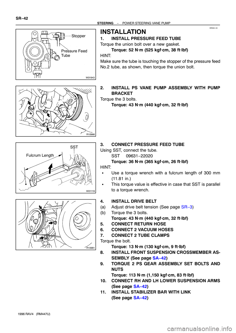
1. INSTALL PRESSURE FEED TUBE
Torque the union bolt over a new gasket.
Torque: 52 N·m (525 kgf·cm, 38 ft·lbf)
HINT:
Make sure the tube is touching the stopper of the pressure feed
No.2 tube, as shown, then torque the union bolt.
2. INSTALL PS VANE PUMP ASSEMBLY WITH PUMP
BRACKET
Torque the 3 bolts.
Torque: 43 N·m (440 kgf·cm, 32 ft·lbf)
3. CONNECT PRESSURE FEED TUBE
Using SST, connect the tube.
SST 09631−22020
Torque: 36 N·m (365 kgf·cm, 26 ft·lbf)
HINT:
�Use a torque wrench with a fulcrum length of 300 mm
(11.81 in.)
�This torque value is effective in case that SST is parallel
to a torque wrench.
4. INSTALL DRIVE BELT
(a) Adjust drive belt tension (See page SR−3)
(b) Torque the 3 bolts.
Torque: 43 N·m (440 kgf·cm, 32 ft·lbf)
5. CONNECT RETURN HOSE
6. CONNECT 2 VACUUM HOSES
7. CONNECT 2 TUBE CLAMPS
Torque the bolt.
Torque: 13 N·m (130 kgf·cm, 9 ft·lbf)
8. INSTALL FRONT SUSPENSION CROSSMEMBER AS-
SEMBLY (See page SA−42)
9. TORQUE 2 PS GEAR ASSEMBLY SET BOLTS AND
NUTS
Torque: 113 N·m (1,150 kgf·cm, 83 ft·lbf)
10. CONNECT RH AND LH LOWER SUSPENSION ARMS
(See page SA−42)
11. INSTALL STABILIZER BAR WITH LINK
(See page SA−42)
Page 1321 of 1354
SR0G2−03
R10984
SST
− STEERINGPOWER STEERING GEAR
SR−47
1996 RAV4 (RM447U)
REMOVAL
NOTICE:
Remove the steering wheel assembly before the steering
gear removal, because there is possibility of breaking of
the spiral cable.
1. PLACE FRONT WHEELS FACING STRAIGHT AHEAD
2. REMOVE STEERING WHEEL PAD (See page SR−12)
3. REMOVE STEERING WHEEL (See page SR−12)
4. REMOVE RH AND LH ENGINE UNDER COVERS
Remove the 13 bolts.
5. DISCONNECT RH AND LH TIE ROD ENDS
(See page SA−10)
6. REMOVE FRONT EXHAUST PIPE
Remove the 2 bolts, 3 nuts and 2 gaskets.
7. REMOVE STABILIZER BAR WITH LINK
(See page SA−48)
8. DISCONNECT NO.2 INTERMEDIATE SHAFT
(See page SR−12)
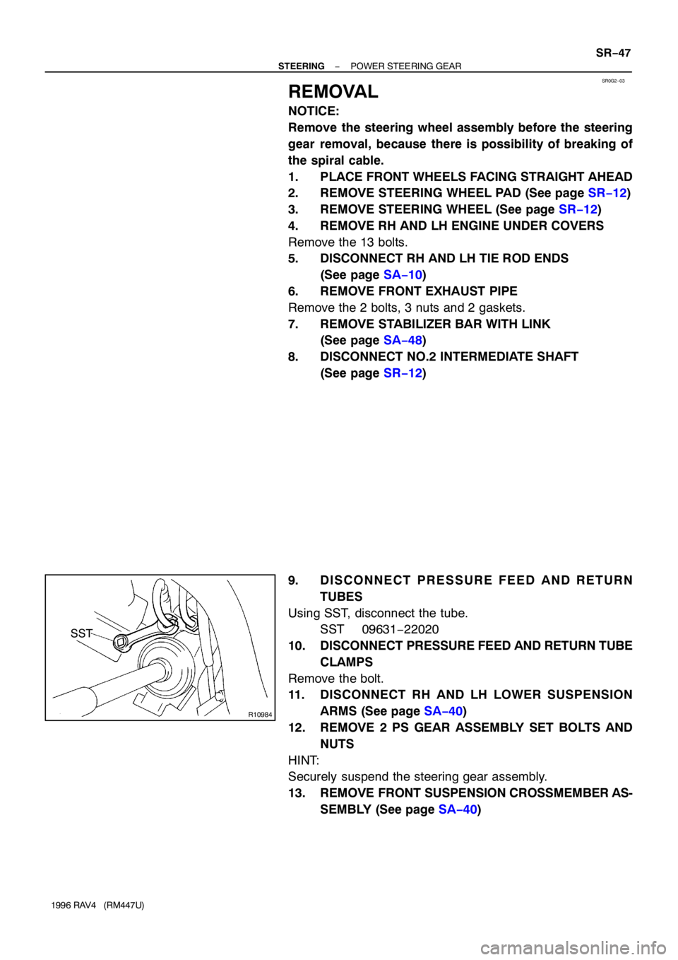
9. DISCONNECT PRESSURE FEED AND RETURN
TUBES
Using SST, disconnect the tube.
SST 09631−22020
10. DISCONNECT PRESSURE FEED AND RETURN TUBE
CLAMPS
Remove the bolt.
11. DISCONNECT RH AND LH LOWER SUSPENSION
ARMS (See page SA−40)
12. REMOVE 2 PS GEAR ASSEMBLY SET BOLTS AND
NUTS
HINT:
Securely suspend the steering gear assembly.
13. REMOVE FRONT SUSPENSION CROSSMEMBER AS-
SEMBLY (See page SA−40)
Page 1331 of 1354

W01262
SST
W01263
SST
Spacer
Lock NutBC
A
W04192
12°
Hexagon Wrench
W01265
SST
− STEERINGPOWER STEERING GEAR
SR−57
1996 RAV4 (RM447U)
12. INSTALL LOCK NUT
(a) Using SST to stop the control valve shaft rotating, torque
a new nut.
SST 09616−00010
Torque: 12 N·m (125 kgf·cm, 9 ft·lbf)
(b) Turn C of SST to obtain dimension A, then set SST, as
shown.
SST 09613−12020
Dimension A: 16.5 − 17.0 mm (0.65 − 0.67 in.)
(c) Stake the nut by turning B of SST until it touches the
spacer of SST.
13. INSTALL RACK HOUSING CAP
(a) Apply sealant to 2 or 3 threads of the cap.
Sealant: Part No.08833−00080, THREE BOND 1344,
LOCTITE 242 or equivalent
(b) Torque the cap.
Torque: 69 N·m (700 kgf·cm, 51 ft·lbf)
14. INSTALL RACK GUIDE SEAT, RACK GUIDE, RACK
GUIDE SPRING AND RACK GUIDE SPRING CAP
(a) Install the seat to the guide.
(b) Apply sealant to 2 or 3 threads of the cap.
Sealant: Part No.08833−00080, THREE BOND 1344,
LOCTITE 242 or equivalent
(c) Temporarily install the cap.
15. ADJUST TOTAL PRELOAD
(a) To prevent the steering rack teeth from damaging the oil
seal lip, temporarily install the RH and LH rack ends.
(b) Using a hexagon wrench (21 mm), torque the rack guide
spring cap.
Torque: 25 N·m (250 kgf·cm, 18 ft·lbf)
(c) Using a hexagon wrench (21 mm), return the cap 12°.
(d) Using SST, turn the control valve shaft right and left 1 or
2 times.
SST 09616−00010
(e) Using a hexagon wrench (21 mm), loosen the cap until the
rack guide spring is not functioning.
Page 1334 of 1354
SR0G6−02
W01119
SST
Fulcrum Length SR−60
− STEERINGPOWER STEERING GEAR
1996 RAV4 (RM447U)
INSTALLATION
1. CONNECT PRESSURE FEED AND RETURN TUBE
CLAMPS
Torque the bolt.
Torque: 13 N·m (130 kgf·cm, 9 ft·lbf)
2. INSTALL FRONT SUSPENSION CROSSMEMBER AS-
SEMBLY (See page SA−42)
3. TORQUE 2 PS GEAR ASSEMBLY SET BOLTS AND
NUTS
Torque: 113 N·m (1,150 kgf·cm, 83 ft·lbf)
4. CONNECT RH AND LH LOWER SUSPENSION ARMS
(See page SA−42)
5. INSTALL STABILIZER BAR WITH LINK
(See page SA−50)
6. INSTALL FRONT EXHAUST PIPE
(a) Torque the 2 bolts with a new gasket.
Torque: 48 N·m (490 kgf·cm, 35 ft·lbf)
(b) Torque 3 new nuts with a new gasket.
Torque: 62 N·m (630 kgf·cm, 46 ft·lbf)
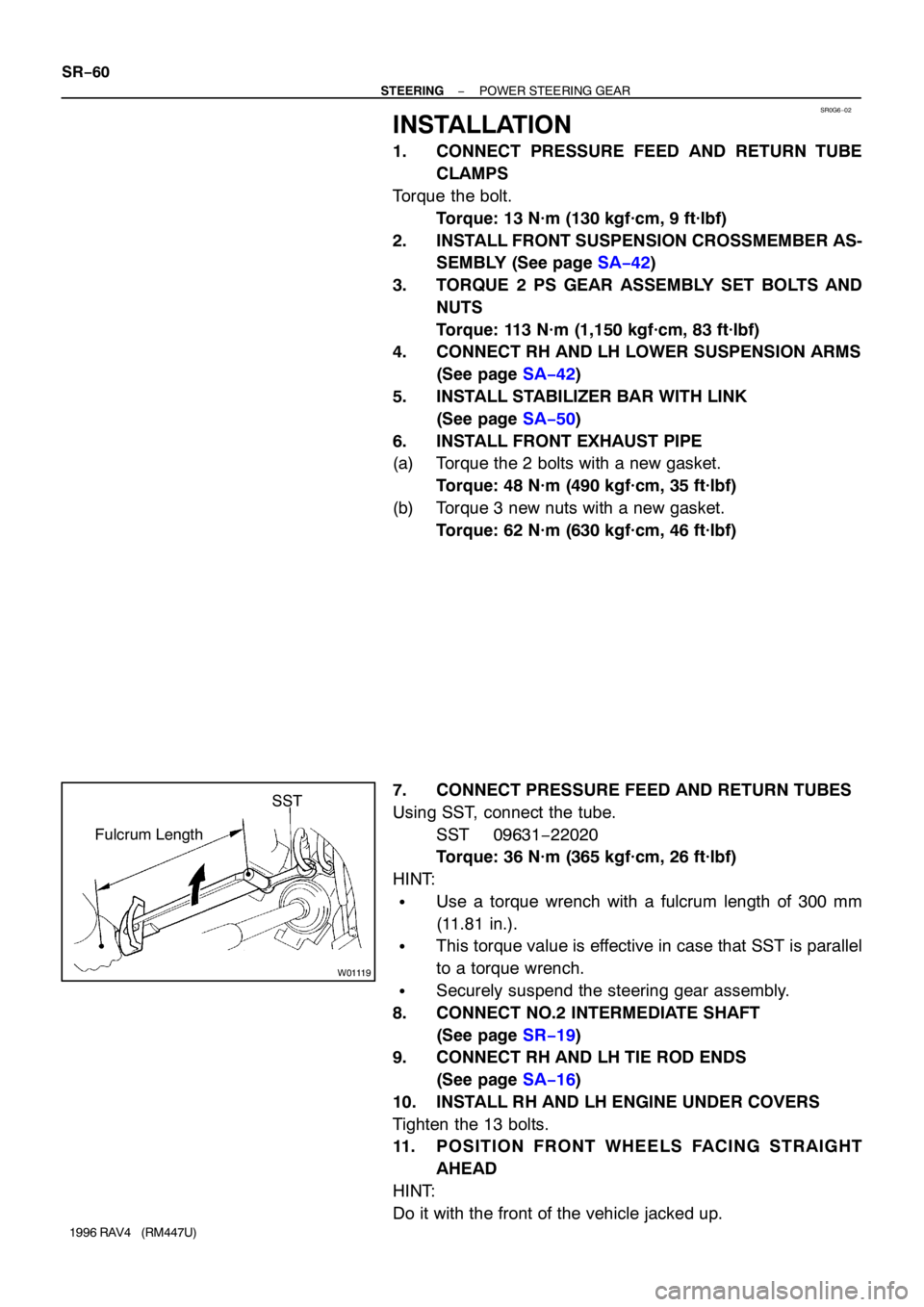
7. CONNECT PRESSURE FEED AND RETURN TUBES
Using SST, connect the tube.
SST 09631−22020
Torque: 36 N·m (365 kgf·cm, 26 ft·lbf)
HINT:
�Use a torque wrench with a fulcrum length of 300 mm
(11.81 in.).
�This torque value is effective in case that SST is parallel
to a torque wrench.
�Securely suspend the steering gear assembly.
8. CONNECT NO.2 INTERMEDIATE SHAFT
(See page SR−19)
9. CONNECT RH AND LH TIE ROD ENDS
(See page SA−16)
10. INSTALL RH AND LH ENGINE UNDER COVERS
Tighten the 13 bolts.
11. POSITION FRONT WHEELS FACING STRAIGHT
AHEAD
HINT:
Do it with the front of the vehicle jacked up.
Page 1335 of 1354
− STEERINGPOWER STEERING GEAR
SR−61
1996 RAV4 (RM447U)
12. CENTER SPIRAL CABLE (See page SR−19)
13. INSTALL STEERING WHEEL
(a) Align the matchmarks on the wheel and steering column
main shaft.
(b) Temporarily tighten the wheel set nut.
(c) Connect the connector.
14. BLEED POWER STEERING SYSTEM
(See page SR−4)
15. CHECK STEERING WHEEL CENTER POINT
16. TORQUE STEERING WHEEL SET NUT
Torque: 34 N·m (350 kgf·cm, 25 ft·lbf)
17. INSTALL STEERING WHEEL PAD (See page SR−19)
18. CHECK FRONT WHEEL ALIGNMENT
(See page SA−4)