Page 519 of 1354
Q06970
Transaxle
Shift Solenoid
Valve No. 1
Shift Solenoid
Valve No. 2
To Cruse Control ECUS2S1ECM
P−B 3
E1 E4E4
P 6152
E1B+
B+
Q08088
S2S1
− DIAGNOSTICSAUTOMATIC TRANSAXLE (A540H)
DI−199
1996 RAV4 (RM447U)
WIRING DIAGRAM
INSPECTION PROCEDURE
1 Measure resistance between terminal S1 or S2 of ECM and body ground.
PREPARATION:
Disconnect the connector from the ECM.
CHECK:
Measure the resistance between terminal S1 or S2 of the ECM
and body ground.
OK:
Resistance: 11 − 15 Ω
OK Check and replace ECM.
NG
Page 541 of 1354
D02302
Cruise Control ECU
OD
C169
Y−B
E620
OD14 − 6 V ECM
D02303
ON
(−)
(+)OD1
− DIAGNOSTICSAUTOMATIC TRANSAXLE (A540H)
DI−221
1996 RAV4 (RM447U)
O/D Cancel Signal Circuit
CIRCUIT DESCRIPTION
While driving uphill with cruise control activated, in order to minimize gear shifting and provide smooth cruis-
ing, O/D may be prohibited temporarily in some conditions.
The cruise control ECU sends O/D cut signals to the ECM as necessary and the ECM cancels O/D shifting
until these signals are discontinued.
WIRING DIAGRAM
INSPECTION PROCEDURE
1 Check voltage between terminal OD1 of ECM and body ground.
PREPARATION:
Turn the ignition switch ON.
CHECK:
Measure the voltage between terminal OD1 of the ECM and
body ground.
OK:
Voltage: 4 − 6 V
OK Proceed to next circuit inspection shown on
problem symptoms table (See page DI−192).
NG
DI419−01
Page 542 of 1354
D02305
ON
Cruise Control ECU
(−)(+)
OD
DI−222
− DIAGNOSTICSAUTOMATIC TRANSAXLE (A540H)
1996 RAV4 (RM447U)
2 Check voltage between terminal OD of cruise control ECU harness side connec-
tor and body ground.
PREPARATION:
(a) Disconnect the cruise control ECU connector.
(b) Turn the ignition switch ON.
CHECK:
Measure the voltage between terminal OD of the cruise control
ECU harness side connector and body ground.
OK:
Voltage: 4 − 6 V
OK Check and replace cruise control ECU (See
page
IN−30).
NG
3 Check harness and connector between cruise control ECU and ECM (See page
IN−30).
NG Repair or replace harness or connector.
OK
Check and replace ECM.
Page 547 of 1354
Q08870
Fuse Block
Junction Connector
FL Block
Stop Light RH Stop Light LHTo ABS ECU
− DIAGNOSTICSAUTOMATIC TRANSAXLE (A540H)
DI−227
1996 RAV4 (RM447U)
Stop Light Switch Circuit
CIRCUIT DESCRIPTION
The purpose of this circuit is to prevent the engine from stalling, while driving in lock−up condition, when
brakes are suddenly applied.
When the brake pedal is operated, this switch sends a signal to ECM. Then the ECM cancels of the lock−up
clutch while braking is in progress.
WIRING DIAGRAM
INSPECTION PROCEDURE
1 Check operation of stop light.
CHECK:
Check if the stop lights go on and off normally when the brake pedal is operated and released.
NG Check and repair stop light circuit.
OK
DI994−01
Page 555 of 1354

(c) Clear the")
BR3890
R06980
Short Pin
DLC1
N09348
Interface Box
Harness VehicleTOYOTA
Tester Hand−held
TOYOTA Break−out−box
− DIAGNOSTICSANTI−LOCK BRAKE SYSTEM
DI−235
1996 RAV4 (RM447U)
(c) Clear the DTC.
(1) Using SST, connect terminals Tc and E1 of the
DLC1.
SST 09843−18020
(2) Disconnect the short pin from the DLC1.
(3) Turn the ignition switch ON.
(4) Clear the DTC stored in ECU by depressing the
brake pedal 8 or more times within 3 seconds (4WD
models) or 5 seconds (2WD models).
(5) Check that the warning light shows the normal
code.
(6) Remove the SST from the terminals of the DLC1.
SST 09843−18020
(7) Connect the short pin to the DLC1.
HINT:
4WD vehicles:
Cancellation can also be done by removing the ECU−B fuse,
but in this case, other memory systems will also canlelled out.
(d) Using TOYOTA break−out−box and TOYOTA hand−held
tester, measure the ECU terminal values.
(1) Turn the ignition switch OFF.
(2) Hook up the TOYOTA hand−held tester and TOYO-
TA break−out−box to the vehicle.
(3) Turn the ignition switch ON.
(4) Read the ECU input / output values by following the
prompts on the tester screen.
HINT:
TOYOTA hand−held tester has a ”Snapshot” function. This re-
cords the measured values and is effective in the diagnosis of
intermittent problems. Please refer to the TOYOTA hand−held
tester / TOYOTA break−out−box operators manual for further
details.
Page 559 of 1354

DIAGNOSTIC TROUBLE CODE CHART
If a malfunction code is displayed during the DTC check, check the circuit listed for tha")
DI41F−02
− DIAGNOSTICSANTI−LOCK BRAKE SYSTEM
DI−239
1996 RAV4 (RM447U)
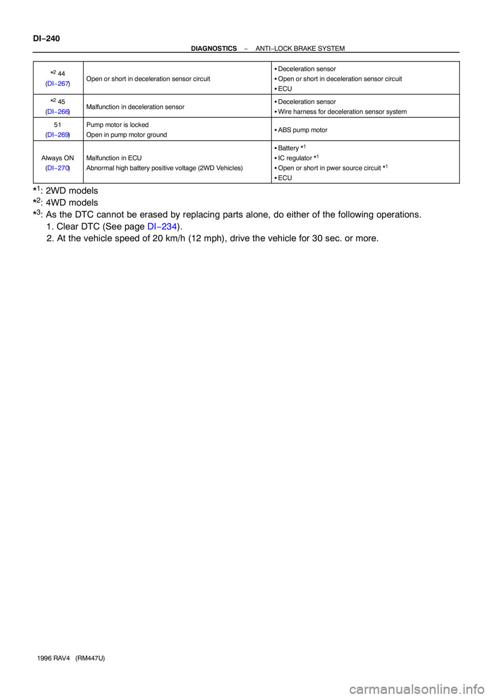
DIAGNOSTIC TROUBLE CODE CHART
If a malfunction code is displayed during the DTC check, check the circuit listed for that code. For details
of each code, turn to the page referred to under the ”See page” for the respective ”DTC No.” in the DTC chart.
HINT:
�Using SST 09843−18020, connect the terminals Tc and E1, and remove the short pin.
�If any abnormality is not found when inspect each inspection parts, inspect the ECU.
DTC No.
(See page)Detection ItemTrouble Area
11
(DI−246)Open circuit in ABS control (solenoid) relay circuit
�ABS control (solenoid) relay
�Open or short in ABS control (solenoid) relay circuit
�ECU
12
(DI−246)Short circuit in ABS control (solenoid) relay circuit
�ABS control (solenoid) relay
�B+ short in ABS control (solenoid) relay circuit
�ECU
*3 13
(DI−250)Open circuit in ABS control (motor) relay circuit
�ABS control (motor) relay
�Open or short in ABS control (motor) relay circuit
�ECU
14
(DI−250)Short circuit in ABS control (motor) relay circuit
�ABS control (motor) relay
�B+ short in ABS control (motor) relay circuit
�ECU
21
(DI−254)Open or short circuit in 2−position solenoid circuit for right front
wheel�ABS actuator
�Open or short in SFRR or SFRH circuit
�ECU
22
(DI−254)Open or short circuit in 2−position solenoid circuit for left front
wheel�ABS actuator
�Open or short in SFLR or SFLH circuit
�ECU
23
(DI−254)Open or short circuit in 2−position solenoid circuit for right rear
wheel�ABS actuator
�Open or short in SRRR or SRRH circuit
�ECU
24
(DI−254)Open or short circuit in 2−position solenoid circuit for left rear
wheel�ABS actuator
�Open or short in SRLR or SRLH circuit
�ECU
*3 31
(DI−257)Right front wheel speed sensor signal malfunction
�Right front, left front, right rear or left rear speed sensor
�Open or short in each speed sensor circuit
�Speed rotor
�ECU*3 32
(DI−257)Left front wheel speed sensor signal malfunction
*3 33
(DI−257)Right rear wheel speed sensor signal malfunction
*3 34
(DI−257)Left rear wheel speed sensor signal malfunction
*2 35
(DI−257)Open circuit in speed sensor circuit�Open in speed sensor circuit
*1 37
(DI−261)Some tire is different size from other tires�Tire size
�ECU
41
(DI−262)Low battery positive voltage
Abnormal high battery positive voltage (2WD Vehicles)
�Battery
�IC regulator
�Open or short in power source circuit
�ECU
*2 43
(DI−266)Malfunction in deceleration sensor (constant output)
�Deceleration sensor
�Wire harness for deceleration sensor system
�ECU
Page 560 of 1354
DI−240
− DIAGNOSTICSANTI−LOCK BRAKE SYSTEM
1996 RAV4 (RM447U)*
2 44
(DI−267)Open or short in deceleration sensor circuit
�Deceleration sensor
�Open or short in deceleration sensor circuit
�ECU
*2 45
(DI−266)Malfunction in deceleration sensor�Deceleration sensor
�Wire harness for deceleration sensor system
51
(DI−269)Pump motor is locked
Open in pump motor ground�ABS pump motor
Always ON
(DI−270)Malfunction in ECU
Abnormal high battery positive voltage (2WD Vehicles)
�Battery *1
�IC regulator *1
�Open or short in pwer source circuit *1
�ECU
*1: 2WD models
*
2: 4WD models
*
3: As the DTC cannot be erased by replacing parts alone, do either of the following operations.
1. Clear DTC (See page DI−234).
2. At the vehicle speed of 20 km/h (12 mph), drive the vehicle for 30 sec. or more.
Page 562 of 1354

TERMINALS OF ECU
2WD")
DI7HG−02
W01411
1 2 3 4 5 6 7 8 9
22 11
21 20 19 18 17 16 15 14 13 1210 1 2 3 4 5 6
7 8 9 10 11 12
A16
A17
DI−242
− DIAGNOSTICSANTI−LOCK BRAKE SYSTEM
1996 RAV4 (RM447U)
TERMINALS OF ECU
2WD Models:
Symbols (Terminal No.)Wiring ColorConditionSTD Voltage (V)
IG1 (A16−2) −
GND (A17−2, 13)B−Y − W−BIG switch ON10 − 14
SR (A17−18) − R+ (A17−8)R−L − R−WIG switch ON ABS warning light OFFBelow 1.5
MR (A17−7) − R+ (A17−8)R−B − R−WIG switch ON10 − 14
SFRH (A17−4) −
GND (A17−2, 13)R−W − W−BIG switch ON ABS warning light OFF10 − 14
SFRR (A17−1) −
GND (A17−2, 13)R−G − W−BIG switch ON ABS warning light OFF10 − 14
SFLH (A17−10) −
GND (A17−2, 13)L−R − W−BIG switch ON ABS warning light OFF10 − 14
SFLR (A17−11) −
GND (A17−2, 13)L−W − W−BIG switch ON ABS warning light OFF10 − 14
SRRR (A17−22) −
GND (A17−2, 13)G−Y − W−BIG switch ON ABS warning light OFF10 − 14
SRRH (A17−21) −
GND (A17−2, 13)G−B − W−BIG switch ON ABS warning light OFF10 − 14
SRLR (A17−12) −
GND (A17−2, 13)BR−R − W−BIG switch ON ABS warning light OFF10 − 14
SRLH (A17−5) −
GND (A17−2, 13)BR−W − W−BIG switch ON ABS warning light OFF10 − 14
AST (A17−16) −
GND (A17−2, 13)G−W − W−BIG switch ON ABS warning light OFF10 − 14
MT (A17−9) −
GND (A17−2, 13)L−O ↔ W−BIG switch ONBelow 1.5
WA (A16−4) −
GND (A17−2, 13)R−Y − W−BIG switch ON ABS warning light ONBelow 2.0
IG switch ON ABS warning light OFF10 − 14
STP (A16−12) −
GND (A17−2, 13)G−W − W−BStop light switch OFFBelow 1.5
Stop light switch ON8 − 14
Tc (A16−9) − GND (A17−2, 13)W−L − W−BIG switch ON10 − 14
Ts (A16−8) − GND (A17−2, 13)L − W−BIG switch ON10 − 14
FR+ (A17−3) − FR− (A17−14)B − WIG switch ONSlowly turn right front wheelAC generation
FL+ (A17−19) − FL− (A17−20)R − GIG switch ONSlowly turn left front wheelAC generation
RR+ (A16−1) − RR− (A16−7)Y −BRIG switch ONSlowly turn right rear wheelAC generation
RL+ (A16−3) − RL− (A16−10)G − RIG switch ONSlowly turn left rear wheelAC generation

DI−199
1996 R")

(+)OD1
− DIAGNOSTICSAUTOMATIC TRANSAXLE (A540H)
DI−221
1996 RAV4 (RM447U)
O/D Cancel Signal Circuit
CIRCUIT DESCRIPT")
(+)
OD
DI−222
− DIAGNOSTICSAUTOMATIC TRANSAXLE (A540H)
1996 RAV4 (RM447U)
2 Check voltage between terminal OD of cruise control ECU harness side connec-
tor and")

DI−227
1996 RAV4 (RM447U)
Stop Light Switch Circuit
CIRCUIT DESCRIPTI")