Page 373 of 1354

IG0317IG0151P25066A06618
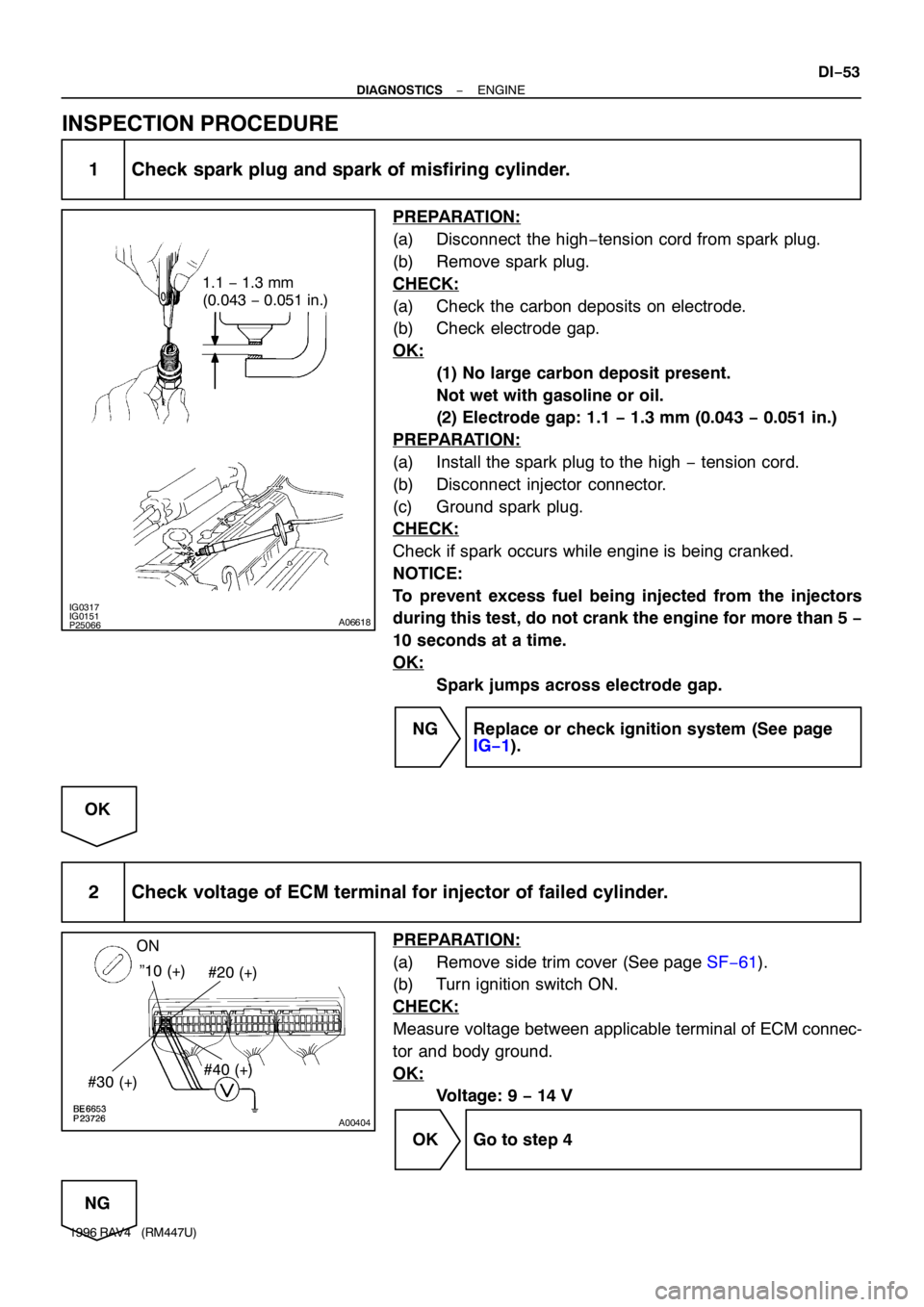
1.1 − 1.3 mm
(0.043 − 0.051 in.)
A00404
”10 (+)
#30 (+)#40 (+) ON
#20 (+)
− DIAGNOSTICSENGINE
DI−53
1996 RAV4 (RM447U)
INSPECTION PROCEDURE
1 Check spark plug and spark of misfiring cylinder.
PREPARATION:
(a) Disconnect the high−tension cord from spark plug.
(b) Remove spark plug.
CHECK:
(a) Check the carbon deposits on electrode.
(b) Check electrode gap.
OK:
(1) No large carbon deposit present.
Not wet with gasoline or oil.
(2) Electrode gap: 1.1 − 1.3 mm (0.043 − 0.051 in.)
PREPARATION:
(a) Install the spark plug to the high − tension cord.
(b) Disconnect injector connector.
(c) Ground spark plug.
CHECK:
Check if spark occurs while engine is being cranked.
NOTICE:
To prevent excess fuel being injected from the injectors
during this test, do not crank the engine for more than 5 −
10 seconds at a time.
OK:
Spark jumps across electrode gap.
NG Replace or check ignition system (See page
IG−1).
OK
2 Check voltage of ECM terminal for injector of failed cylinder.
PREPARATION:
(a) Remove side trim cover (See page SF−61).
(b) Turn ignition switch ON.
CHECK:
Measure voltage between applicable terminal of ECM connec-
tor and body ground.
OK:
Voltage: 9 − 14 V
OK Go to step 4
NG
Page 374 of 1354
DI−54
− DIAGNOSTICSENGINE
1996 RAV4 (RM447U)
3 Check injector resistance of misfiring cylinder (See page SF−21).
NG Replace injector.
OK
Check for open and short in harness and con-
nector between injector and ECM (See page
IN−30).
4 Check fuel pressure (See page SF−5).
NG Check and repair fuel pomp, pressure regulator,
fuel pipe line and filter (See page SF−1).
OK
5 Check injector injection (See page SF−21).
NG Replace injector.
OK
6 Check EGR system (See page SF−45).
NG Repair EGR system.
OK
7 Check manifold absolute pressure sensor and engine coolant temp. sensor (See
page DI−21, DI−29).
Page 668 of 1354

EM−2
− ENGINE MECHANICALCO/HC
1996 RAV4 (RM447U)
6. TROUBLESHOOTING
If the CO/HC concentration does not comply with regulations,
troubleshoot in the order given below.
(a) Check the oxygen sensor operation (See page DI−42).
(b) See the table below for possible causes, then inspect and
correct the applicable causes if necessary.
HCCOProblemsCauses
HighNormalRough idle4. Faulty ignitions:
�Incorrect timing
�Fouled, shorted or improperly gapped plugs
�Open or or crossed high−tension cords
�Cracked distributor cap
5. Incorrect valve clearance
6. Leaky EGR valve
7. Leaky intake and exhaust valves
8. Leaky cylinder
HighLowRough idle
(Fluctuating HC reading)1. Vacuum leaks:
�PCV hose
�EGR valve
�Intake manifold
�Throttle body
�IAC valve
�Brake booster line
2. Lean mixture causing misfire
HighHighRough idle
(Black smoke from exhaust)1. Restricted air filter
2. Faulty SFI system:
�Faulty pressure regulator
�Clogged fuel return line
�Defective ECT sensor
�Defective IAT sensor
�Faulty ECM
�Faulty injector
�Faulty throttle position sensor
�MAP sensor
Page 702 of 1354

S01653
1 2
S01646
S01647
S01645
S01432
EM−36
− ENGINE MECHANICALCYLINDER HEAD
1996 RAV4 (RM447U)
(c) Disconnect the engine wire protector from the 2 mounting
bolts of the No. 2 timing belt cover in the sequence shown.
(d) Remove the 4 nuts, grommets, head cover and gasket.
HINT:
Arrange the grommets in the correct order, so that they can be
reinstalled into their original positions. This minimizes any pos-
sibility of oil leakage due to reuse of the grommets in different
positions.
27. DISCONNECT ENGINE WIRE
(a) Remove the 2 bolts, and disconnect the engine wire pro-
tector from the LH side of the intake manifold.
(b) Disconnect the 4 injector connectors.
(c) w/ A/C:
Disconnect the A/C compressor connector.
(d) Disconnect the crankshaft position sensor connector.
(e) Disconnect the 3 clamps from the No. 2 timing bet cover
and generator drive belt adjusting bar.
(f) Disconnect the engine wire protector from the 2 brackets
on the front side of the intake manifold.
(g) Remove the RH scuff plate, RH cowl side trim and RH
floor carpet center cover.
(h) Disconnect the 2 ECM connectors.
(i) Disconnect the 2 connectors from the connectors on the
bracket.
(j) Disconnect the Connector from the J/B No. 4.
(k) Disconnect the wire clamp from the bracket.
(l) Pull out the engine wire from the cabin.
(m) Take out the engine wire between the cylinder head and
intake manifold.
28. DISCONNECT TIMING BELT FROM CAMSHAFT TIM-
ING PULLEY (See page EM−15)
29. REMOVE CAMSHAFT TIMING PULLEY (See page
EM−15)
30. REMOVE NO. 1 IDLER PULLEY AND TENSION
SPRING
Page 707 of 1354

S01798
2
108
5 3
4
96 7 1
S01767
S01763
S01764
− ENGINE MECHANICALCYLINDER HEAD
EM−41
1996 RAV4 (RM447U)
34. REMOVE CYLINDER HEAD AND INTAKE MANIFOLD
ASSEMBLY
(a) Uniformly loosen and remove the 10 cylinder head bolts,
in several passes, in the sequence shown.
NOTICE:
Cylinder head warpage or cracking could result from re-
moving bolts in incorrect order.
(b) Lift the cylinder head from the dowels on the cylinder
block, and place the cylinder head on wooden blocks on
a bench.
HINT:
If the cylinder head is difficult to the lift off, pry between the cylin-
der head and cylinder block with a screwdriver.
NOTICE:
Be careful not to damage the contact surfaces of the cylin-
der head and cylinder block.
35. REMOVE AIR TUBE
(a) Disconnect the air hose from the intake manifold.
(b) Remove the 2 bolts, hose clamp and air tube.
36. REMOVE INTAKE MANIFOLD
Remove the 6 bolts, 2 nuts and intake manifold and gasket.
37. REMOVE AIR HOSE FOR AIR ASSIST SYSTEM
Disconnect the air hose from the cylinder head port, and re-
move the air hose.
38. REMOVE DELIVERY PIPE AND INJECTORS (See
page SF−19)
Page 721 of 1354

EM1B9−02
P13638
Adhesive
S01764
S01763
S01648
− ENGINE MECHANICALCYLINDER HEAD
EM−55
1996 RAV4 (RM447U)
INSTALLATION
1. INSTALL OIL PRESSURE SWITCH
(a) Apply adhesive to 2 or 3 threads.
Adhesive:
Part No. 08833−00080, THREE BOND 1344 or equiva-
lent
(b) Install the oil pressure switch.
2. INSTALL INJECTORS AND DELIVERY PIPE (See page
SF−23)
3. INSTALL AIR HOSE FOR AIR ASSIST SYSTEM
Connect the air hose to the cylinder head port.
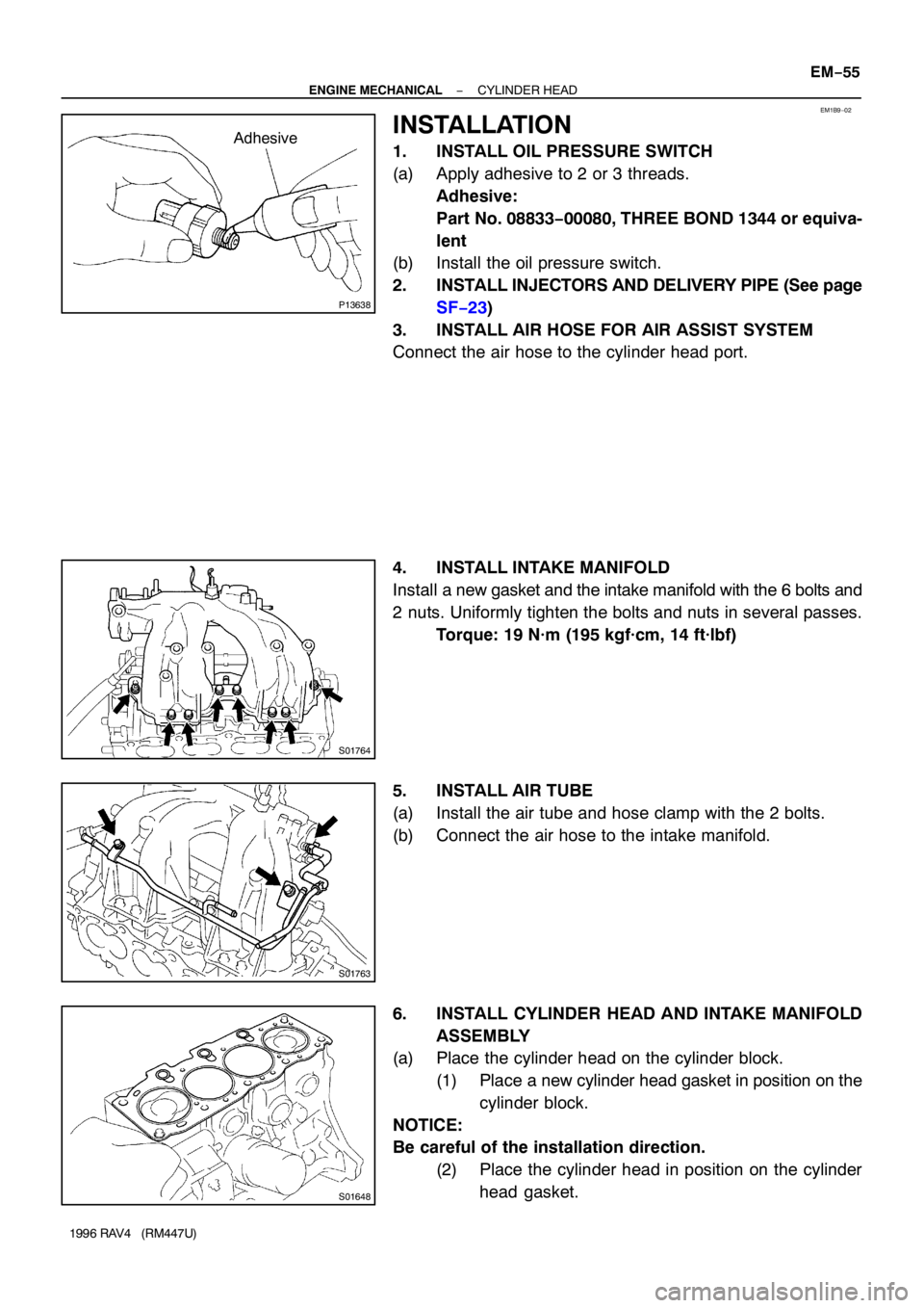
4. INSTALL INTAKE MANIFOLD
Install a new gasket and the intake manifold with the 6 bolts and
2 nuts. Uniformly tighten the bolts and nuts in several passes.
Torque: 19 N·m (195 kgf·cm, 14 ft·lbf)
5. INSTALL AIR TUBE
(a) Install the air tube and hose clamp with the 2 bolts.
(b) Connect the air hose to the intake manifold.
6. INSTALL CYLINDER HEAD AND INTAKE MANIFOLD
ASSEMBLY
(a) Place the cylinder head on the cylinder block.
(1) Place a new cylinder head gasket in position on the
cylinder block.
NOTICE:
Be careful of the installation direction.
(2) Place the cylinder head in position on the cylinder
head gasket.
Page 725 of 1354

S01805
S01793
9 10
3 45 6
1 2
7 8
EM7797
Seal Packing
S01649
S01645
− ENGINE MECHANICALCYLINDER HEAD
EM−59
1996 RAV4 (RM447U)
(6) Install the bearing caps in their proper locations.
(7) Apply a light coat of engine oil on the threads and
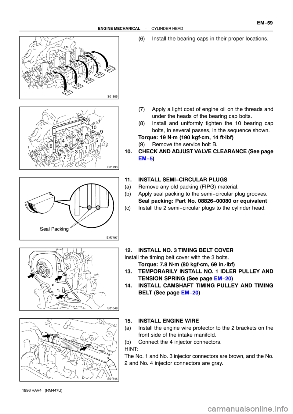
under the heads of the bearing cap bolts.
(8) Install and uniformly tighten the 10 bearing cap
bolts, in several passes, in the sequence shown.
Torque: 19 N·m (190 kgf·cm, 14 ft·lbf)
(9) Remove the service bolt B.
10. CHECK AND ADJUST VALVE CLEARANCE (See page
EM−5)
11. INSTALL SEMI−CIRCULAR PLUGS
(a) Remove any old packing (FIPG) material.
(b) Apply seal packing to the semi−circular plug grooves.
Seal packing: Part No. 08826−00080 or equivalent
(c) Install the 2 semi−circular plugs to the cylinder head.
12. INSTALL NO. 3 TIMING BELT COVER
Install the timing belt cover with the 3 bolts.
Torque: 7.8 N·m (80 kgf·cm, 69 in.·lbf)
13. TEMPORARILY INSTALL NO. 1 IDLER PULLEY AND
TENSION SPRING (See page EM−20)
14. INSTALL CAMSHAFT TIMING PULLEY AND TIMING
BELT (See page EM−20)
15. INSTALL ENGINE WIRE
(a) Install the engine wire protector to the 2 brackets on the
front side of the intake manifold.
(b) Connect the 4 injector connectors.
HINT:
The No. 1 and No. 3 injector connectors are brown, and the No.
2 and No. 4 injector connectors are gray.
Page 799 of 1354
29
G
Position of Parts in Engine Compartment
I 1 Idle Air Control Valve R 1Radiator Fan Motor
I 2 Igniter R 2 Rear Washer Motor
I 3 Ignition Coil and Distributor
I 4 Ignition Coil and Distributor S 1 Solenoid Valve SLD
I 5 Injector No. 1 S 2 Starter
I 6 Injector No. 2 S 3 Starter
I 7 Injector No. 3
I 8 Injector No. 4 T 1 Throttle Position Sensor
I 9 Intake Air Temp. Sensor
V 1 Vapor Pressure Sensor
K 1 Knock Sensor V 2 Vehicle Speed Sensor (Combination Meter)
V 3 Vehicle Speed Sensor (Front)
M 1 Manifold Absolute Pressure Sensor V 4 Vehicle Speed Sensor (Rear)
V 5 VSV (Center Diff. Lock No. 1)
N 1 Noise Filter (Ignition System) V 6 VSV (Center Diff. Lock No. 2)
V 7 VSV (EGR)
O 1 Oil Pressure SW V 8 VSV (EVAP)
O 2 Oxygen Sensor (Bank 1 Sensor 1) V 9 VSV (Vapor Pressure Sensor)
O 3 Oxygen Sensor (Bank 1 Sensor 2)
W 1 Water Temp. Sender
P 1 Park/Neutral Position SW (A/T)