Page 1124 of 1354

SA0TA−03
R10657
R10655
SA−10
− SUSPENSION AND AXLEFRONT AXLE HUB
1996 RAV4 (RM447U)
REMOVAL
1. REMOVE FRONT WHEEL
Torque: 103 N·m (1,050kgf·cm, 76 ft·lbf)
2. CHECK BEARING BACKLASH AND AXLE HUB DEVI-
ATION
(a) Remove the 2 bolts and brake caliper from the steering
knuckle.
(b) Support the brake caliper securely.
(c) Remove the disc.
(d) Using a dial indicator near the center of the axle hub and
check the backlash in the bearing shaft direction.
Maximum: 0.05 mm (0.0020 in.)
If the backlash exceeds the maximum, replace the bearing.
(e) Using a dial indicator, check the deviation at the surface
of the axle hub outside the hub bolt.
Maximum: 0.07 mm (0.0028 in.)
If the deviation exceeds the maximum, replace the axle hub and
bearing.
3. REMOVE DRIVE SHAFT LOCK NUT
(a) Install the disc and brake caliper.
Torque: 107 N·m (1,090 kgf·cm, 79 ft·lbf)
(b) Remove the cotter pin and lock cap.
(c) With applying the brakes, remove the nut.
Torque: 216 N·m (2,200 kgf·cm, 159 ft·lbf)
(d) Remove the brake caliper and disc.
4. w/ ABS:
REMOVE ABS SPEED SENSOR AND WIRE HARNESS
FROM STEERING KNUCKLE
Remove the 2 bolts, ABS speed sensor and wire harness.
Torque:
ABS speed sensor x Steering knuckle:
8 N·m (80 kgf·cm, 69 in.·lbf)
ABS speed sensor wire x Steering knuckle:
5 N·m (55 kgf·cm, 48 in.·lbf)
5. LOOSEN 2 NUTS ON LOWER SIDE ON SHOCK AB-
SORBER
Torque: 158 N·m (1,610 kgf·cm, 117 ft·lbf)
HINT:
Do not remove the 2 nuts and bolts.
6. D I S C O N N E C T T I E R O D E N D F R O M S T E E R I N G
KNUCKLE
(a) Remove the cotter pin and nut.
Torque: 49 N·m (500 kgf·cm, 36 ft·lbf)
Page 1131 of 1354
SA0TE−01
R10733
SST
R10759
− SUSPENSION AND AXLEFRONT WHEEL HUB BOLT
SA−17
1996 RAV4 (RM447U)
FRONT WHEEL HUB BOLT
REPLACEMENT
1. REMOVE FRONT WHEEL
2. REMOVE FRONT BRAKE CALIPER AND DISC
(a) Remove the 2 bolts and brake caliper from the steering
knuckle.
(b) Support the brake caliper securely and remove the disc.
3. REMOVE HUB BOLT
Using SST, remove the hub bolt.
SST 09628−10011
4. INSTALL HUB BOLT
(a) Install a washer and nut to the hub bolt, as shown in the
illustration.
(b) Install the hub bolt with torquing the nut.
5. INSTALL FRONT BRAKE DISC AND CALIPER
Install the disc and brake caliper with the 2 bolts.
Torque: 107 N·m (1,090 kgf·cm, 79 ft·lbf)
HINT:
Check the disc runout (See page BR−26).
6. INSTALL FRONT WHEEL
Torque: 103 N·m (1,050 kgf·cm 76 ft·lbf)
Page 1142 of 1354

W01213
RH
LH
R10353
SST
F01439
w/o ABS w/ ABS
SST
SA1453
W00880
SST SA−28
− SUSPENSION AND AXLEFRONT DRIVE SHAFT
1996 RAV4 (RM447U)
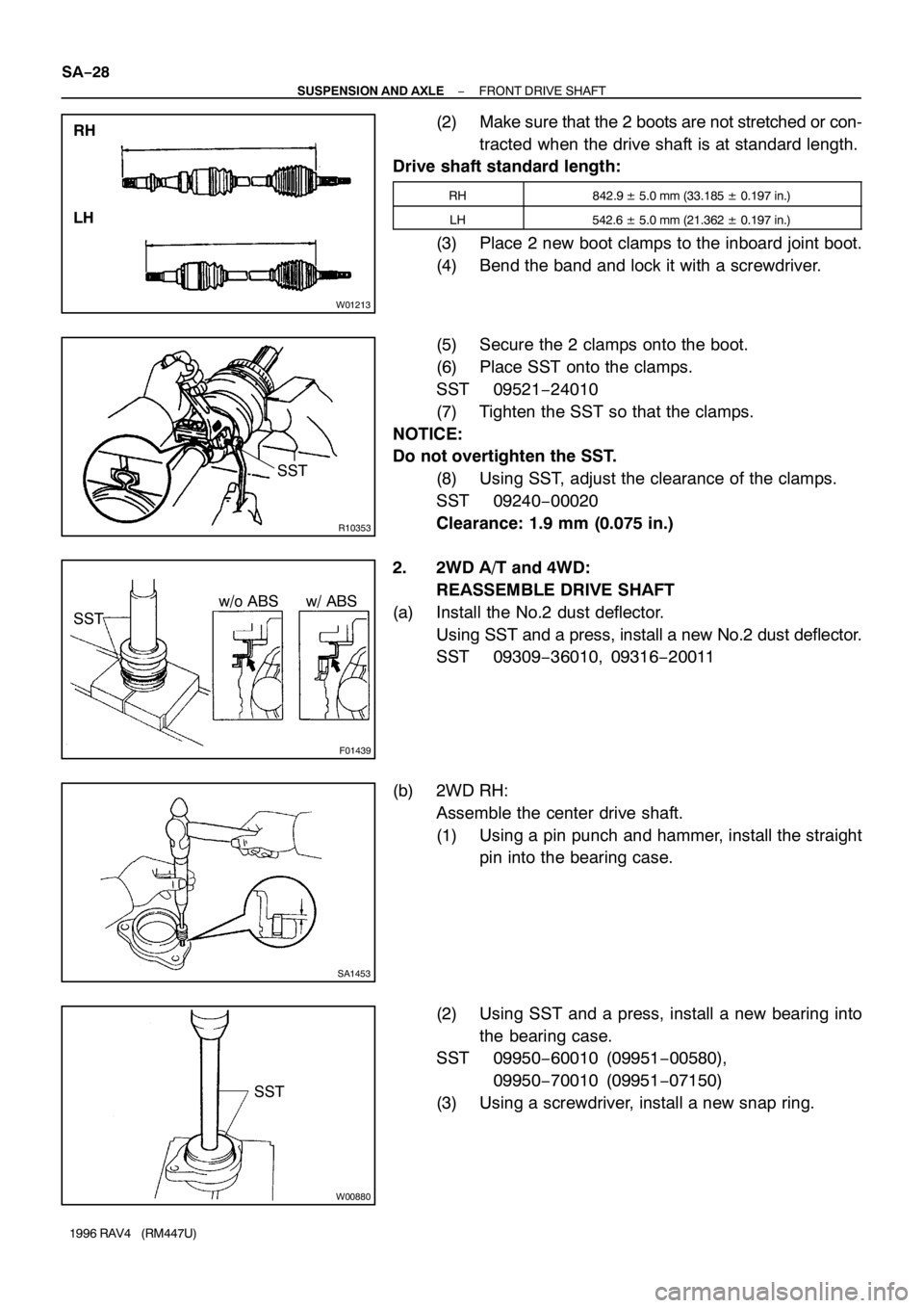
(2) Make sure that the 2 boots are not stretched or con-
tracted when the drive shaft is at standard length.
Drive shaft standard length:
RH842.9 ± 5.0 mm (33.185 ± 0.197 in.)
LH542.6 ± 5.0 mm (21.362 ± 0.197 in.)
(3) Place 2 new boot clamps to the inboard joint boot.
(4) Bend the band and lock it with a screwdriver.
(5) Secure the 2 clamps onto the boot.
(6) Place SST onto the clamps.
SST 09521−24010
(7) Tighten the SST so that the clamps.
NOTICE:
Do not overtighten the SST.
(8) Using SST, adjust the clearance of the clamps.
SST 09240−00020
Clearance: 1.9 mm (0.075 in.)
2. 2WD A/T and 4WD:
REASSEMBLE DRIVE SHAFT
(a) Install the No.2 dust deflector.
Using SST and a press, install a new No.2 dust deflector.
SST 09309−36010, 09316−20011
(b) 2WD RH:
Assemble the center drive shaft.
(1) Using a pin punch and hammer, install the straight
pin into the bearing case.
(2) Using SST and a press, install a new bearing into
the bearing case.
SST 09950−60010 (09951−00580),
09950−70010 (09951−07150)
(3) Using a screwdriver, install a new snap ring.
Page 1148 of 1354
SA0TM−01
R10824
SST Vinyl
Tape
R10825
SST SA−34
− SUSPENSION AND AXLEFRONT SHOCK ABSORBER
1996 RAV4 (RM447U)
DISASSEMBLY
REMOVE COIL SPRING
(a) Install 2 nuts and a bolt to the bracket at the lower portion
of the shock absorber and secure it in a vise.
(b) Using SST, compress the coil spring.
SST 09727−30021
HINT:
To prevent the coil spring from damaging, wind vinyl tape on the
coil spring.
NOTICE:
�When holding the shock absorber with the coil spring
removed, do not hold it by the spring lower seat. Also,
do not knock the spring lower seat.
�Do not use an impact wrench. It will damage the SST.
(c) Remove the cap.
(d) Using SST to hold the spring upper seat, remove the nut.
SST 09729−22031
(e) Remove these parts from the shock absorber:
�Suspension support
�Dust seal
�Spring upper seat
�Upper insulator and coil spring
�Spring bumper and lower insulator
Page 1187 of 1354
SA0UJ−01
W04156
R10756
− SUSPENSION AND AXLEREAR DIFFERENTIAL CARRIER
SA−73
1996 RAV4 (RM447U)
REMOVAL
1. REMOVE DRIVE SHAFTS (See page SA−62)
HINT:
Support the drive shafts securely.
2. REMOVAL PROPELLER SHAFT (See page PR−2)
HINT:
Support the propeller shaft securely.
3. DRAIN DIFFERENTIAL OIL
Torque: 49 N·m (500 kgf·cm, 36 ft·lbf)
4. REMOVE DIFFERENTIAL
(a) Support the differential with a jack.
(b) Remove the 2 rear mounting bolts.
Torque: 65 N·m (660 kgf·cm, 48 ft·lbf)
(c) Remove the 2 front mounting bolts and differential.
Torque: 132 N·m (1,350 kgf·cm, 98 ft·lbf)
(d) Remove the 2 bolts and differential rear mount cushion
from the differential.
Torque: 137 N·m (1,400 kgf·cm, 101 ft·lbf)
Page 1210 of 1354

SA0UU−03
R10779
R10764
SST
R10765
SST SA−96
− SUSPENSION AND AXLEREAR SUSPENSION ARM AND COIL SPRING
1996 RAV4 (RM447U)
REMOVAL
1. REMOVE REAR WHEEL
Torque: 103 N·m (1,050 kgf·cm, 76 ft·lbf)
2. 2WD:
REMOVE AXLE SHAFT (See page SA−52)
3. 4WD:
REMOVE REAR DRIVE SHAFT (See page SA−62)
4. REMOVE BRAKE DRUM
5. REMOVE 2 BRAKE LINE CLAMP BOLTS
Torque:
Bracket: 18 N·m (185 kgf·cm, 13 ft·lbf)
Clamp: 13 N·m (130 kgf·cm, 9 ft·lbf)
6. REMOVE PARKING BRAKE CABLE CLAMP BOLT
Torque: 19 N·m (195 kgf·cm, 14 ft·lbf)
7. w/ ABS:
REMOVE ABS SPEED SENSOR AND WIRE HARNESS
Torque:
ABS speed sensor: 8 N·m (80 kgf·cm, 69 in.·lbf)
Wire harness: 13 N·m (130 kgf·cm, 9 ft·lbf)
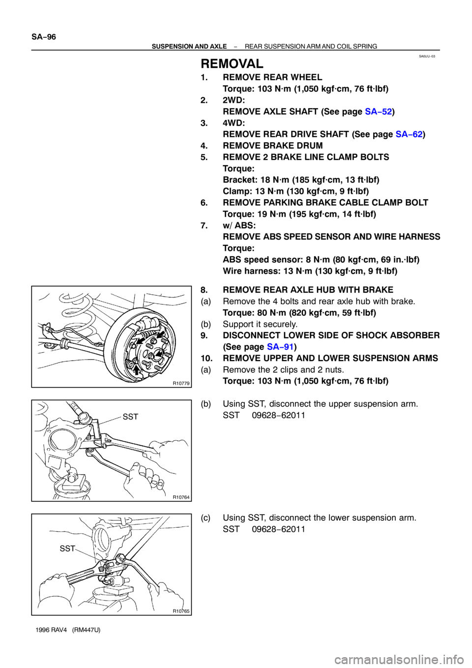
8. REMOVE REAR AXLE HUB WITH BRAKE
(a) Remove the 4 bolts and rear axle hub with brake.
Torque: 80 N·m (820 kgf·cm, 59 ft·lbf)
(b) Support it securely.
9. DISCONNECT LOWER SIDE OF SHOCK ABSORBER
(See page SA−91)
10. REMOVE UPPER AND LOWER SUSPENSION ARMS
(a) Remove the 2 clips and 2 nuts.
Torque: 103 N·m (1,050 kgf·cm, 76 ft·lbf)
(b) Using SST, disconnect the upper suspension arm.
SST 09628−62011
(c) Using SST, disconnect the lower suspension arm.
SST 09628−62011
Page 1215 of 1354

SF0Q4−03
− SFISFI SYSTEM
SF−1
1996 RAV4 (RM447U)
SFI SYSTEM
PRECAUTION
1. BEFORE WORKING ON THE FUEL SYSTEM, DISCON-
NECT THE NEGATIVE (−) TERMINAL CABLE FROM
THE BATTERY
HINT:
Any diagnostic trouble code retained by the computer will be
erased when the negative (−) terminal cable is removed.
Therefore, if necessary, read the diagnosis before removing the
terminal.
2. DO NOT SMOKE OR WORK NEAR AN OPEN FLAME
WHEN WORKING ON THE FUEL SYSTEM
3. KEEP GASOLINE AWAY FROM RUBBER OR LEATH-
ER PARTS
4. MAINTENANCE PRECAUTIONS
(a) In event of engine misfire, these precautions should be
taken.
(1) Check proper connection to battery terminals, etc.
(2) After repair work, check that the ignition coil termi-
nals and all other ignition system lines are recon-
nected securely.
(3) When cleaning the engine compartment, be espe-
cially careful to protect the electrical system from
water.
(b) Precautions when handling oxygen sensor.
(1) Do not allow oxygen sensor to drop or hit against an
object.
(2) Do not allow the sensor to come into contact with
water.
5. IF VEHICLE IS EQUIPPED WITH MOBILE RADIO SYS-
TEM (HAM, CB, ETC.)
If the vehicle is equipped with a mobile communication system,
refer to the precaution in the IN section.
6. AIR INDUCTION SYSTEM
(a) Separation of the engine oil dipstick, oil filler cap, PCV
hose, etc. may cause the engine to run out of tune.
(b) Disconnection, looseness or cracks in the parts of the air
induction system between the throttle body and cylinder
head will allow air suction and cause the engine to run out
of tune.
7. ELECTRONIC CONTROL SYSTEM
(a) Before removing SFI wiring connectors, terminals, etc.,
first disconnect the power by either turning the ignition
switch to LOCK or disconnecting the negative (−) terminal
cable from the battery.
HINT:
Always check the diagnostic trouble code before disconnecting
the negative (−) terminal cable from the battery.
Page 1246 of 1354
S01910
Ohmmeter
Vacuum IDL
E2
0.60 mm
S01910
Ohmmeter
Vacuum IDL
E20.50 or
0.70 mm SF−32
− SFITHROTTLE BODY
1996 RAV4 (RM447U)
(b) Apply vacuum to the throttle opener.
(c) Insert a 0.60 mm (0.024 in.) thikness gauge between the
throttle stop screw and stop lever.
(d) Connect the test probe of an ohmmeter to the terminals
IDL and E2 of the sensor.
(e) Gradually turn the sensor clockwise untill the ohmmeter
deflects, and secure it with the 2 set screws.
(f) Recheck the continuity between terminals IDL and E2.
Clearance between
lever and stop screwContinuity (IDL − E2)
0.50 mm (0.020 in.)Continuity
0.70 mm (0.028 in.)No continuity