Page 1012 of 1399
PP3KJ−01
−
PREPARATION AIR CONDITIONING
PP−71
120
Author�: Date�:
1996 LAND CRUISER (RM451U)
AIR CONDITIONING
SST (Special Service Tools)
07110−58060Air Conditioner Service Tool Set
(07117−58060)Refrigerant Drain Service Valve
(07117−58070)T−Joint
(07117−58080)Quick Disconnect AdapterDischarge (Diam.: 16 mm)
(07117−58090)Quick Disconnect AdapterSuction (Diam.: 13 mm)
(07117−78050)Refrigerant Charging Gauge
(07117−88060)Refrigerant Charging HoseDischarge (Color: Red)
(07117−88070)Refrigerant Charging HoseSuction (Color: Blue)
(07117−88080)Refrigerant Charging HoseUtility (Color: Green)
07112−66040Magnetic Clutch Remover
07112−76060Magnetic Clutch Stopper
07114−84010Snap Ring Pliers
Brought to you by BirfMark
Brought to you by BirfMark
Version 1.11 - 03/16/2010
Page 1013 of 1399
PP−72
−
PREPARATION AIR CONDITIONING
121
Author�: Date�:
1996 LAND CRUISER (RM451U)
07114−84020Snap Ring Pliers
07116−38360Gas Leak Detector Assembly
Brought to you by BirfMark
Brought to you by BirfMark
Version 1.11 - 03/16/2010
Page 1014 of 1399
PP2YZ−01
−
PREPARATION AIR CONDITIONING
PP−73
1996 LAND CRUISER (RM451U)
RECOMMENDED TOOLS
09082−00040TOYOTA Electrical Tester.
Brought to you by BirfMark
Brought to you by BirfMark
Version 1.11 - 03/16/2010
Page 1016 of 1399
PR06N−01
−
PROPELLER SHAFT TROUBLESHOOTING
PR−1
849
Author�: Date�:
1996 LAND CRUISER (RM451U)
TROUBLESHOOTING
PROBLEM SYMPTOMS TABLE
Use the table below to help you find the cause of the problem. The numbers \
indicate the priority of the likely
cause of the problem. Check each part in order. If necessary, replace these parts.
SymptomSuspect AreaSee page
Noise3. Seeve yoke spline: worn
4. Spider bearing: worn or stuckPR−4
PR−4
Vibration
1. Sleeve yoke spline: stuck
2. Propeller shaft: runout
3. Propeller shaft: imbalancePR−4
PR−4
−
Brought to you by BirfMark
Brought to you by BirfMark
Version 1.11 - 03/16/2010
Page 1019 of 1399

PR0310
PR06Q−01
PR0014
Matchmarks
PR0056
PR−4
−
PROPELLER SHAFT PROPELLER SHAFT ASSEMBLY
1996 LAND CRUISER (RM451U)
INSPECTION
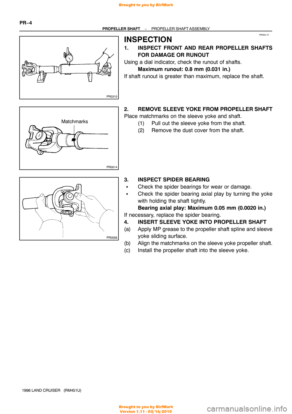
1. INSPECT FRONT AND REAR PROPELLER SHAFTS FOR DAMAGE OR RUNOUT
Using a dial indicator, check the runout of shafts. Maximum runout: 0.8 mm (0.031 in.)
If shaft runout is greater than maximum, replace the shaft.
2. REMOVE SLEEVE YOKE FROM PROPELLER SHAFT
Place matchmarks on the sleeve yoke and shaft.
(1) Pull out the sleeve yoke from the shaft.
(2) Remove the dust cover from the shaft.
3. INSPECT SPIDER BEARING
�Check the spider bearings for wear or damage.
�Check the spider bearing axial play by turning the yoke
with holding the shaft tightly.
Bearing axial play: Maximum 0.05 mm (0.0020 in.)
If necessary, replace the spider bearing.
4. INSERT SLEEVE YOKE INTO PROPELLER SHAFT
(a) Apply MP grease to the propeller shaft spline and sleeve yoke sliding surface.
(b) Align the matchmarks on the sleeve yoke propeller shaft.
(c) Install the propeller shaft into the sleeve yoke.
Brought to you by BirfMark
Brought to you by BirfMark
Version 1.11 - 03/16/2010
Page 1022 of 1399

Z04247
ColorDrit Mark
Bearing Cup
Drit Mark
Yoke
Q07142
Type A Type B X
610.0 mm (24.016 in.)
Y
545.0 mm (21.457 in.)
X
Y Differential
Side
Z00755
PR0081
Q07338
−
PROPELLER SHAFT SPIDER BEARING
PR−7
855
Author�: Date�:
1996 LAND CRUISER (RM451U)
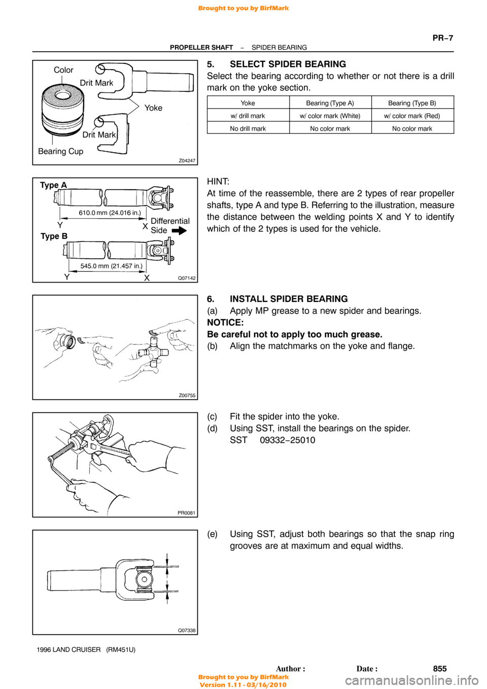
5. SELECT SPIDER BEARING
Select the bearing according to whether or not there is a drill
mark on the yoke section.
YokeBearing (T ype A)Bearing (Type B)
w/ drill markw/ color mark (White)w/ color mark (Red)
No drill markNo color markNo color mark
HINT:
At time of the reassemble, there are 2 types of rear propeller
shafts, type A and type B. Referring to the illustration, measure
the distance between the welding points X and Y to identify
which of the 2 types is used for the vehicle.
6. INSTALL SPIDER BEARING
(a) Apply MP grease to a new spider and bearings.
NOTICE:
Be careful not to apply too much grease.
(b) Align the matchmarks on the yoke and flange.
(c) Fit the spider into the yoke.
(d) Using SST, install the bearings on the spider. SST 09332−25010
(e) Using SST, adjust both bearings so that the snap ring grooves are at maximum and equal widths.
Brought to you by BirfMark
Brought to you by BirfMark
Version 1.11 - 03/16/2010
Page 1023 of 1399

PR0069
PR0031
PR−8
−
PROPELLER SHAFT SPIDER BEARING
856
Author�: Date�:
1996 LAND CRUISER (RM451U)
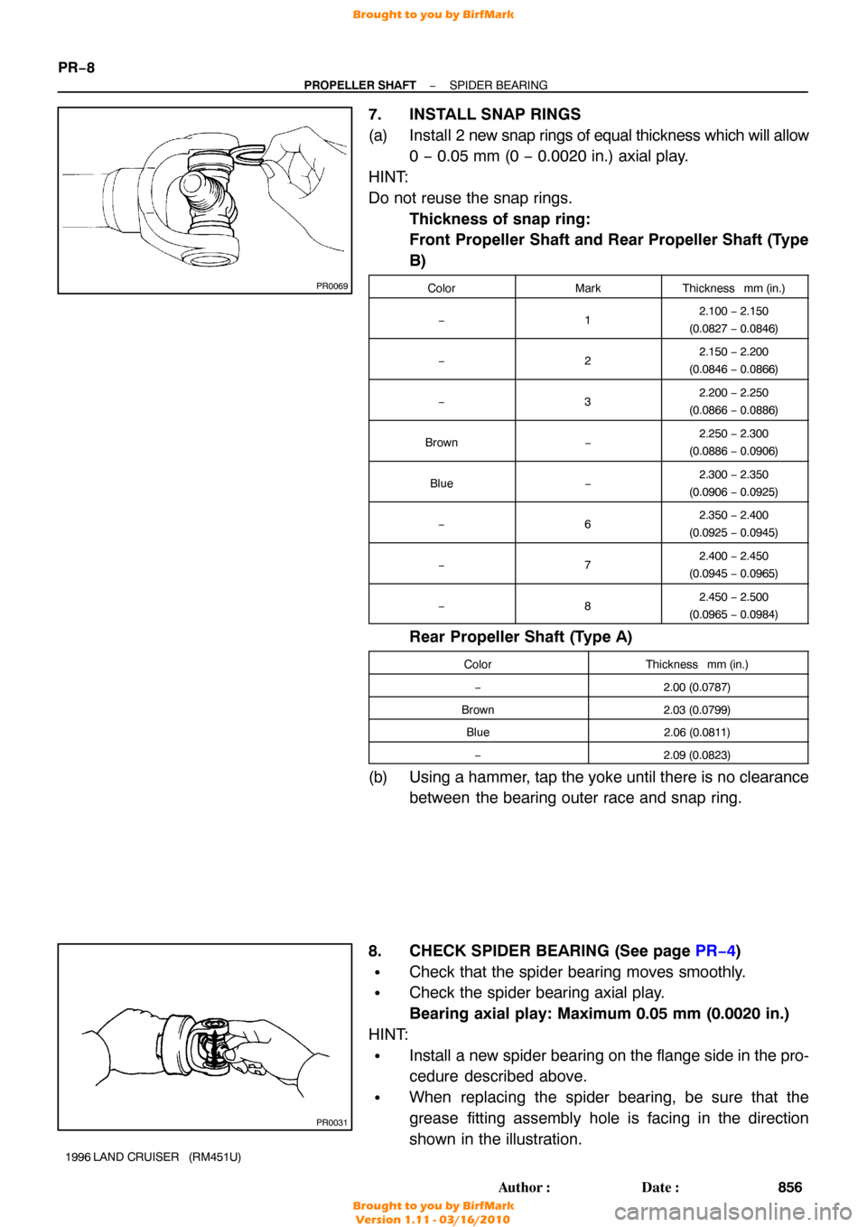
7. INSTALL SNAP RINGS
(a) Install 2 new snap rings of equal thickness which will allow
0 − 0.05 mm (0 − 0.0020 in.) axial play.
HINT:
Do not reuse the snap rings. Thickness of snap ring:
Front Propeller Shaft and Rear Propeller Shaft (Type
B)
ColorMarkThickness mm (in.)
−12.100 − 2.150
(0.0827 − 0.0846)
−22.150 − 2.200
(0.0846 − 0.0866)
−32.200 − 2.250
(0.0866 − 0.0886)
Brown−2.250 − 2.300
(0.0886 − 0.0906)
Blue−2.300 − 2.350
(0.0906 − 0.0925)
−62.350 − 2.400
(0.0925 − 0.0945)
−72.400 − 2.450
(0.0945 − 0.0965)
−82.450 − 2.500
(0.0965 − 0.0984)
Rear Propeller Shaft (Type A)
ColorThickness mm (in.)
−2.00 (0.0787)
Brown2.03 (0.0799)
Blue2.06 (0.0811)
−2.09 (0.0823)
(b) Using a hammer, tap the yoke until there is no clearance
between the bearing outer race and snap ring.
8. CHECK SPIDER BEARING (See page PR−4 )
�Check that the spider bearing moves smoothly.
�Check the spider bearing axial play.
Bearing axial play: Maximum 0.05 mm (0.0020 in.)
HINT:
�Install a new spider bearing on the flange side in the pro-
cedure described above.
�When replacing the spider bearing, be sure that the
grease fitting assembly hole is facing in the direction
shown in the illustration.
Brought to you by BirfMark
Brought to you by BirfMark
Version 1.11 - 03/16/2010
Page 1024 of 1399
Q09100
SPIDER GREASE FITTING ASSEMBLY DIRECTION
Front Propeller ShaftThe Figure at left shows the locations of
the grease fittings as seen from the rear.
Sleeve Yoke
No.1No.2
No.1
SPIDER GREASE FITTING ASSEMBLY DIRECTION
Rear Propeller Shaft Sleeve Yoke
Sleeve Yoke No.1
No.2
No.1
Sleeve Yoke The Figure at left shows the locations of
the grease fittings as seen from the
rear.
No.2
No.2
−
PROPELLER SHAFT SPIDER BEARING
PR−9
857
Author�: Date�:
1996 LAND CRUISER (RM451U)
Brought to you by BirfMark
Brought to you by BirfMark
Version 1.11 - 03/16/2010