Page 832 of 1399

EM2196
−
ENGINE MECHANICAL CYLINDER HEAD
EM−47
1996 LAND CRUISER (RM451U)
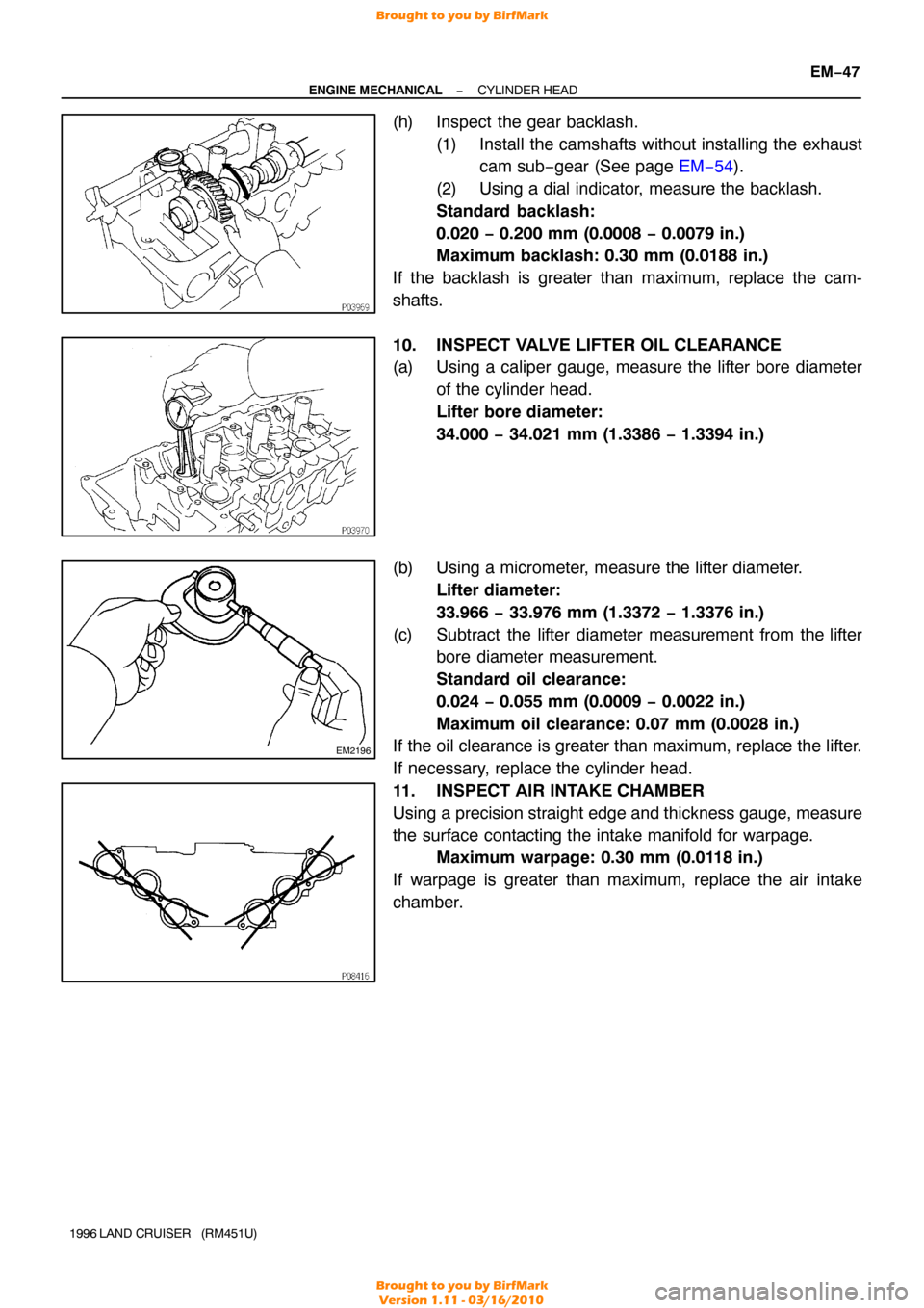
(h) Inspect the gear backlash.
(1) Install the camshafts without installing the exhaustcam sub−gear (See page EM−54).
(2) Using a dial indicator, measure the backlash.
Standard backlash:
0.020 − 0.200 mm (0.0008 − 0.0079 in.)
Maximum backlash: 0.30 mm (0.0188 in.)
If the backlash is greater than maximum, replace the cam-
shafts.
10. INSPECT VALVE LIFTER OIL CLEARANCE
(a) Using a caliper gauge, measure the lifter bore diameter of the cylinder head.
Lifter bore diameter:
34.000 − 34.021 mm (1.3386 − 1.3394 in.)
(b) Using a micrometer, measure the lifter diameter. Lifter diameter:
33.966 − 33.976 mm (1.3372 − 1.3376 in.)
(c) Subtract the lifter diameter measurement from the lifter bore diameter measurement.
Standard oil clearance:
0.024 − 0.055 mm (0.0009 − 0.0022 in.)
Maximum oil clearance: 0.07 mm (0.0028 in.)
If the oil clearance is greater than maximum, replace the lifter.
If necessary, replace the cylinder head.
11. INSPECT AIR INTAKE CHAMBER
Using a precision straight edge and thickness gauge, measure
the surface contacting the intake manifold for warpage. Maximum warpage: 0.30 mm (0.0118 in.)
If warpage is greater than maximum, replace the air intake
chamber.
Brought to you by BirfMark
Brought to you by BirfMark
Version 1.11 - 03/16/2010
Page 833 of 1399
P22604
EM−48
−
ENGINE MECHANICAL CYLINDER HEAD
1996 LAND CRUISER (RM451U)
12. INSPECT INTAKE MANIFOLD
Using a precision straight edge and thickness gauge, measure
the surface contacting the cylinder head and air intake chamber
for warpage.
Maximum warpage: 0.30 mm (0.0118 in.)
If warpage is greater than maximum, replace the manifold.
13. INSPECT EXHAUST MANIFOLDS
Using a precision straight edge and thickness gauge, measure
the surface contacting the cylinder head for warpage. Maximum warpage: 0.30 mm (0.0118 in.)
If warpage is greater than maximum, replace the manifold.
14. INSPECT CHAIN TENSIONER
Check that the plunger moves smoothly.
Brought to you by BirfMark
Brought to you by BirfMark
Version 1.11 - 03/16/2010
Page 834 of 1399

EM1Q6−01
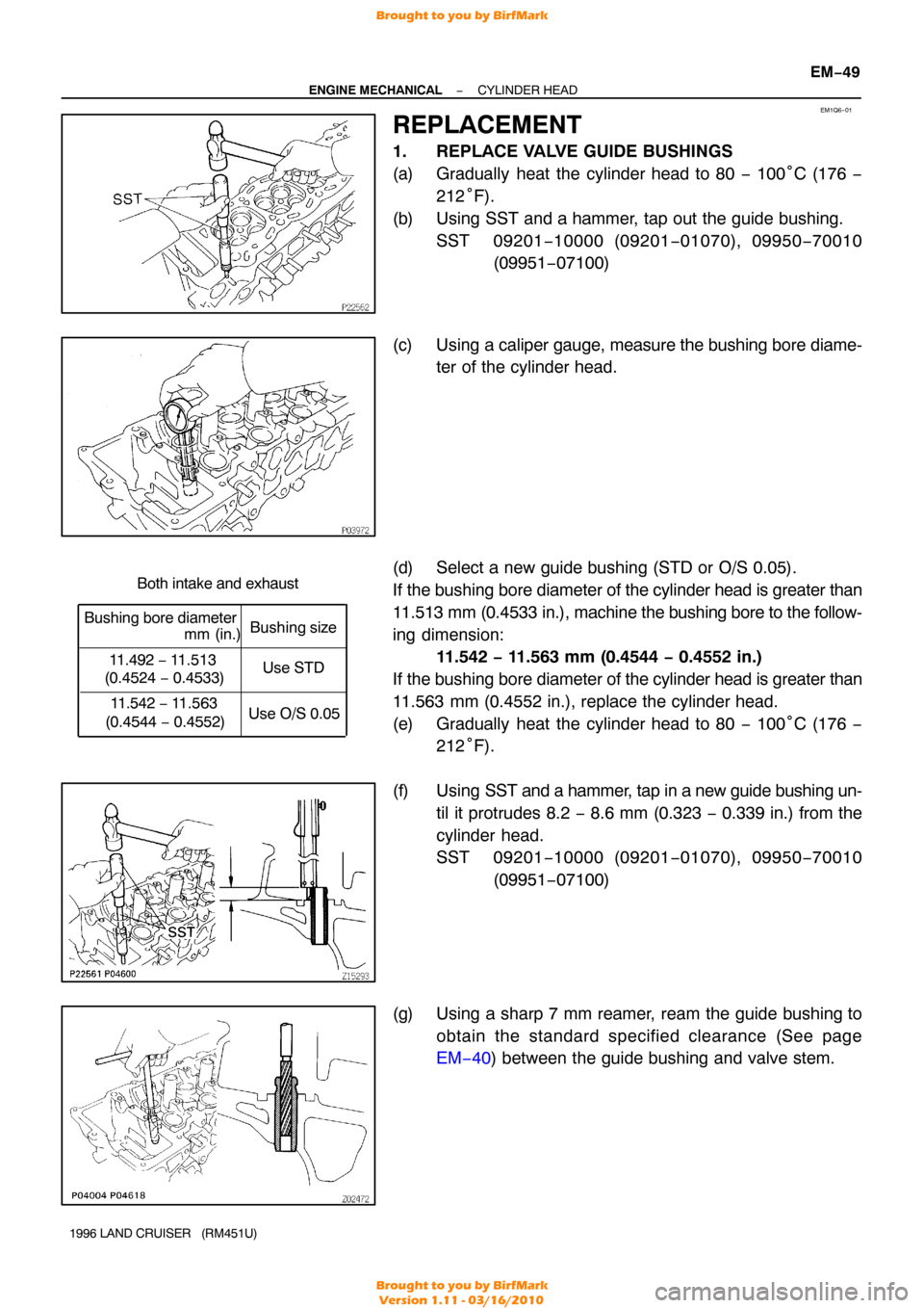
Both intake and exhaust
Bushing bore diametermm (in.)Bushing
size
11.492 − 11.513
(0.4524 − 0.4533)
11.542 − 11.563
(0.4544 − 0.4552) Use STD
Use O/S 0.05
−
ENGINE MECHANICAL CYLINDER HEAD
EM−49
1996 LAND CRUISER (RM451U)
REPLACEMENT
1. REPLACE VALVE GUIDE BUSHINGS
(a) Gradually heat the cylinder head to 80 − 100°C (176 −
212 °F).
(b) Using SST and a hammer, tap out the guide bushing. SST 09201 −10000 (09201 −01070), 09950 −70010
(09951 −07100)
(c) Using a caliper gauge, measure the bushing bore diame- ter of the cylinder head.
(d) Select a new guide bushing (STD or O/S 0.05).
If the bushing bore diameter of the cylinder head is greater than
11.513 mm (0.4533 in.), machine the bushing bore to the follow-
ing dimension: 11.542 − 11.563 mm (0.4544 − 0.4552 in.)
If the bushing bore diameter of the cylinder head is greater than
11.563 mm (0.4552 in.), replace the cylinder head.
(e) Gradually heat the cylinder head to 80 − 100°C (176 −
212 °F).
(f) Using SST and a hammer, tap in a new guide bushing un-
til it protrudes 8.2 − 8.6 mm (0.323 − 0.339 in.) from the
cylinder head.
SST 09201 −10000 (09201 −01070), 09950 −70010
(09951 −07100)
(g) Using a sharp 7 mm reamer, ream the guide bushing to obtain the standard specified clearance (See page
EM−40 ) between the guide bushing and valve stem.
Brought to you by BirfMark
Brought to you by BirfMark
Version 1.11 - 03/16/2010
Page 837 of 1399
EM−52
−
ENGINE MECHANICAL CYLINDER HEAD
1996 LAND CRUISER (RM451U)
(b) Install the TVV.
3. INSTALL ECT SENDER GAUGE
4. INSTALL ECT CUT SWITCH
5. INSTALL ECT SENSOR
6. INSTALL VALVES
(a) Using SST, push in a new oil seal.
SST 09236−00101 (09236 −15010)
HINT:
Different oil seals are used for the intake and exhaust.
(b) Install the valve (1), spring seat (2), valve spring (3) and spring retainer (4).
(c) Using SST, compress the valve spring and place the 2 keepers around the valve stem.
SST 09202−70020 (09202 −00010)
Brought to you by BirfMark
Brought to you by BirfMark
Version 1.11 - 03/16/2010
Page 838 of 1399

−
ENGINE MECHANICAL CYLINDER HEAD
EM−53
1996 LAND CRUISER (RM451U)
(d) Using a plastic−faced hammer, lightly tap the valve stem
tip to ensure a proper fit.
7. INSTALL VALVE LIFTERS AND SHIMS
(a) Install the valve lifter and shim.
(b) Check that the valve lifter rotates smoothly by hand.
8. INSTALL ACCELERATOR CABLE BRACKET AND THROTTLE CABLE BRACKET
9. INSTALL 2 ENGINE WIRE CLAMP BRACKETS
10. INSTALL NO. 1 AND NO. 2 ENGINE HANGERS Torque: 41 N·m (420 kgf·cm, 30 ft·lbf)
11. INSTALL NO. 1 WATER BYPASS HOSE
12. ASSEMBLE AIR INTAKE CHAMBER AND INTAKE MANIFOLD ASSEMBLY
(a) Install 2 new gaskets and the air intake chamber with the
6 bolts and 2 nuts.
Torque: 21 N·m (210 kgf·cm, 15 ft·lbf)
(b) Connect the vacuum sensing hose to the fuel pressure regulator.
13. INSTALL AIR INTAKE CHAMBER AND INTAKE MAN- IFOLD ASSEMBLY
(a) Place a new gasket so that the rear mark is toward the rear side.
(b) Install the intake manifold with the 10 bolts and 2 nuts.
Torque: 21 N·m (210 kgf·cm, 15 ft·lbf)
(c) Connect the 2 vacuum hoses to the TVV.
14. INSTALL HEATER INLET PIPE AND HOSE
Install the heater hose to the cylinder head, and connect the
pipe to the intake manifold with the 2 bolts. Torque: 21 N·m (210 kgf·cm, 15 ft·lbf)
15. INSTALL EGR PIPE
(a) Temporarily install the union nut to the EGR valve.
(b) Install a new gasket and the EGR pipe to the cylinder head with the 2 bolts.
Torque: 21 N·m (210 kgf·cm, 15 ft·lbf)
(c) Tighten the union nut. Torque: 78 N·m (800 kgf·cm, 58 ft·lbf)
16. INSTALL WATER OUTLET
Install a new gasket and the water outlet with the 2 nuts. Torque: 21 N·m (210 kgf·cm, 15 ft·lbf)
17. INSTALL GENERATOR BRACKET
Install the generator bracket with the 2 bolts. Torque: 43 N·m (440 kgf·cm, 32 ft·lbf)
Brought to you by BirfMark
Brought to you by BirfMark
Version 1.11 - 03/16/2010
Page 839 of 1399

EM1E7−01
EM−54
−
ENGINE MECHANICAL CYLINDER HEAD
1996 LAND CRUISER (RM451U)
INSTALLATION
1. INSTALL CYLINDER HEAD AND INTAKE MANIFOLD ASSEMBLY
(a) Place the cylinder head on the cylinder head. (1) Apply seal packing to the 2 locations as shown.
Seal packing: Part No. 08826−00080 or equivalent
NOTICE:
Do not apply too much seal packing
(2) Place a new cylinder head gasket in position on the
cylinder block.
NOTICE:
Be careful of the installation direction. (3) Place the cylinder head in position on the cylinderhead gasket.
(b) Install the cylinder head bolts.
HINT:
�The cylinder head bolts are tightened in 3 progressive
steps (steps (b), (d) and (e)).
�If any cylinder head bolt is broken or deformed, replace
it.
(1) Apply a light coat of engine oil on the threads and under the heads of the cylinder head bolts.
(2) Install and uniformly tighten the 14 cylinder head
bolts and plate washers in several passes, in the se-
quence shown.
Torque: 39 N·m (400 kgf·cm, 29 ft·lbf)
If any of the cylinder head bolts does not meet the torque speci-
fication, replace the cylinder head bolt.
(3) Mark the front of the cylinder head bolt head withpaint.
(4) Retighten the cylinder head bolts by 90 ° in the nu-
merical order shown.
(5) Retighten the cylinder head bolts by an additional 90°.
(6) Check that the painted mark is now facing rearward.
Brought to you by BirfMark
Brought to you by BirfMark
Version 1.11 - 03/16/2010
Page 846 of 1399

−
ENGINE MECHANICAL CYLINDER HEAD
EM−61
1996 LAND CRUISER (RM451U)
14. INSTALL HEATER PIPE
Install a new gasket, the heater pipe and ground cable with the
2 bolts and 2 nuts.
Torque:
20 N·m (200 kgf·cm, 14 ft·lbf) for bolt:
21 N·m (210 kgf·cm, 15 ft·lbf) for nut
15. INSTALL NO. 1 AND NO. 2 EXHAUST MANIFOLDS
(a) Install 2 new gaskets, No. 1 exhaust manifold and No. 2
exhaust manifold with the 13 nuts.
Torque: 39 N·m (400 kgf·cm, 29 ft·lbf)
(b) Install the No. 1 heat insulator and No. 2 heat insulator with the 6 bolts.
Torque: 19 N·m (195 kgf·cm, 14 ft·lbf)
16. INSTALL FRONT EXHAUST PIPE
(a) Install 2 new gaskets and the front exhaust pipe with the 4 nuts.
Torque: 63 N·m (630 kgf·cm, 46 ft·lbf)
(b) Install the No. 1 support bracket with the 2 bolts. Torque: 24 N·m (240 kgf·cm, 17 ft·lbf)
(c) Connect the clamp and tighten the clamp bolt.
Torque: 19.5 N·m (195 kgf·cm, 14 ft·lbf)
(d) Connect the front exhaust pipe to the rear TWC with a new gasket, 2 bolts and 2 nuts.
Torque: 46 N·m (470 kgf·cm, 34 ft·lbf)
17. CONNECT NO. 2 WATER BYPASS PIPE
Connect the bypass pipe to the cylinder head with the 3 bolts.
Torque: 20 N·m (200 kgf·cm, 14 ft·lbf)
18. CONNECT ENGINE WIRE
(a) Place the engine wire on the intake manifold.
(b) Connect the connectors. (1) Connect the 3 injector connectors.
(2) Connect the EGR gas temp. sensor connector.
(c) Connect the clamp of the No.6 injector wire to the bracket.
(d) Connect the engine wire clamp.
(e) Connect the engine wire clamp.
(f) Connect the connectors. (1) Connect the connector for the emission control
valve set assembly.
(2) Connect the 3 injector connectors.
(g) Install the bolt holding the engine wire to the intake man- ifold.
Brought to you by BirfMark
Brought to you by BirfMark
Version 1.11 - 03/16/2010
Page 847 of 1399

EM−62
−
ENGINE MECHANICAL CYLINDER HEAD
1996 LAND CRUISER (RM451U)
(h) Connect the engine wire to the intake manifold and cylin-
der block with the 2 bolts.
(i) Connect the PNP switch connector.
(j) Connect the 2 heated oxygen sensor connectors.
(k) Connect the connectors.
(1) Connect the Knock sensor connector.
(2) Connect the oil level sensor connector.
(3) Connect the 2 connectors to tthe ransmission.
(4) Connect the starter connector.
(l) Connect the engine wire to the cylinder block with the bolt.
(m) Connect the connectors.
(1) Connect the ECT sender gauge connector.
(2) Connect the ECT cut switch connector.
(3) Connect the ECT sensor connector.
(4) Connect the knock sensor connector.
(5) Connect the crankshaft position sensor connector.
19. CONNECT FUEL INLET HOSE
Connect the fuel inlet hose to the fuel filter with 2 new gaskets
and the union bolt. Torque: 29 N·m (300 kgf·cm, 22 ft·lbf)
20. INSTALL INTAKE MANIFOLD STAY
Install the intake manifold stay with the 2 bolts. Torque: 36 N·m (360 kgf·cm, 26 ft·lbf)
21. INSTALL OIL DIPSTICKS AND GUIDES FOR ENGINE AND TRANSMISSION
(a) Install a new O−ring to the dipstick guide.
(b) Apply a light coat of engine oil on the O −ring.
(c) Push in the dipstick guide into the guide hole of the oil pan.
(d) Install the dipstick guide with the 2 bolts. Torque: 20 N·m (200 kgf·cm, 14 ft·lbf)
22. INSTALL THROTTLE BODY (See page SF−48)
23. INSTALL GENERATOR AND DRIVE BELTS (See page CH−19 )
Brought to you by BirfMark
Brought to you by BirfMark
Version 1.11 - 03/16/2010